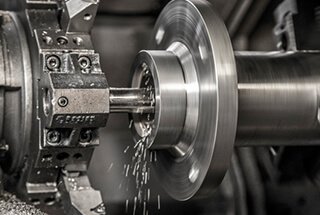
Have you ever wondered how a CNC lathe can create such precise parts? In this article, we’ll explore the fascinating world of CNC lathes, focusing on the number of axes they use and how these axes determine their capabilities. By the end, you’ll understand how these machines achieve such incredible precision.
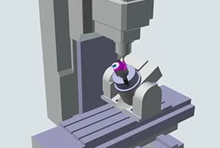
To process highly precise parts, CNC lathes require precise definition of the worktable and cutting tool positions using accurate coordinate values. The movement in multi-dimensional space is represented and controlled through digital computing information.
These movement axes are referred to as CNC axes.
In this discussion, we will explore the number of axes in a CNC lathe and how to identify them.
Related reading: What Is a Lathe?
A CNC (Computer Numerical Control) lathe is a sophisticated machine tool that utilizes computer-programmed instructions to perform high-precision turning operations around various axes. The number and configuration of axes are crucial components of a CNC lathe’s capabilities, with different combinations available for various machining requirements.
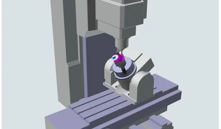
The number of axes in a CNC machine defines its degrees of freedom and, consequently, its complexity and versatility. While simpler CNC lathes typically operate with two primary axes (X and Z), more advanced models can incorporate additional axes for enhanced functionality. For example:
Each axis represents a specific direction of motion:
Understanding these axes and their functions is crucial for efficient CNC lathe programming and operation. In the following sections, we will delve deeper into how to identify and utilize these axes in CNC lathe machining processes.
Related reading: What Is a Lathe?
The number of CNC axes is a critical factor in determining the capabilities and versatility of CNC machines. Here’s an optimized explanation of CNC axes:
CNC (Computer Numerical Control) machines utilize multiple axes to perform precise cutting and shaping operations. The number of axes directly influences the machine’s ability to manipulate the workpiece, the complexity of parts it can produce, and the level of detail it can achieve.
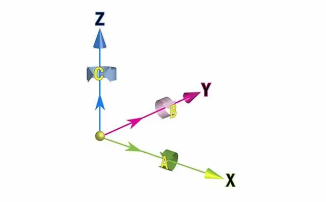
At the core, CNC machines operate on a Cartesian coordinate system:
These three axes form the foundation of 3-axis CNC machines, which are common in standard milling operations. However, advanced CNC systems can incorporate additional axes:
CNC lathes typically operate with two primary axes (X and Z) and a spindle that rotates the workpiece. More advanced lathes may incorporate additional axes for complex turning and milling operations.
The number of axes in a CNC machine correlates with its capabilities:
Multi-axis machining centers can perform intricate operations, reduce setup time, and improve overall part accuracy. However, they also require more sophisticated programming and typically come at a higher cost.
As CNC technology continues to advance, machines with even more axes are being developed for ultra-precise and complex manufacturing processes, pushing the boundaries of what’s possible in modern machining.
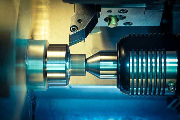
The number of axes in a CNC system is determined by the system itself. Typically, CNC lathes come with 2 axes as standard, while CNC milling machines come with 3 axes as standard.
However, the number of axes in a CNC system can vary, with some lathes capable of 6-axis linkage or even controlling more than 10 axes. The exact number of axes is determined by the system’s function.
How many CNC lathes are there?
The Z axis is parallel to the axis on the workpiece, allowing the tool to move along the side of the material as the part rotates about the Z axis (C). The movement along the Z axis determines the length of the job.
The X axis is perpendicular to the Z axis, allowing the tool to move back and forth along the X axis to determine the diameter of the part.
The C axis is defined as the rotary table in the center of the workbench, which rotates 360 degrees around the Z axis. The front end of the shaft is a rotary head that can also rotate 360 degrees around the Z axis, becoming the C axis.
Related reading: 4-Axis and 5-Axis CNC Machining Basics
1. Rotary motion:
The rotary motion around the X, Y and Z axes is represented by A, B and C respectively, and the positive direction is determined according to the right-hand screw rule.
2. Additional axis:
The movement of the additional axis is represented by U, V, W, P, Q and R.
The rotation of the additional shaft is indicated by D, E and F.
Related reading: 5 Axis Machining
On a CNC lathe, the Z axis is located horizontally on the operator’s left side. By convention, the Z axis is referred to as being near or far from the main axis. Some CNC lathes also have a Y axis, which allows the carriage to be adjusted for off-axis live tool drilling.
The CNC lathe is primarily used for processing reverse rolling parts, with the cutting tool only requiring lateral and longitudinal movements.
As a result, CNC lathes typically only control the X and Z axes, making them typical two-axis CNC equipment. However, some CNC lathes may also have a Y axis.

