After unpacking, the user should check that the machine matches the packing list and pay attention to ensure that: a. The machine tool was not damaged during handling. b. No machine parts are missing. c. The machine and parts are intact. Lifting of guillotine shear When lifting the machine, appropriate lifting equipment and steel wire […]

After unpacking, the user should check that the machine matches the packing list and pay attention to ensure that:
a. The machine tool was not damaged during handling. b. No machine parts are missing. c. The machine and parts are intact.
When lifting the machine, appropriate lifting equipment and steel wire rope must be selected according to the weight of the machine, otherwise unexpected safety accidents may occur.
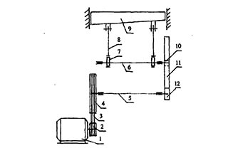
There is a lifting bolt on the upper part of the shearing machine. When lifting, the lifting wire rope must be padded with soft objects to prevent damage to the paint (see the figure below).
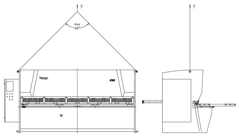
Attention:
The installation accuracy of the guillotine shear will directly affect the machine’s service performance, so it must be installed by professionals (or personnel sent by the manufacturer).
The machine should be installed on a stable and hard foundation, and the working area’s ground should be covered with a thick concrete layer, as shown in the foundation drawing, and leveled (maximum flatness of 2mm/m).
Fifteen days before installation, the user can dig the foundation, pour the machine base, reserve four anchor bolt installation holes, and pay attention to placing the four sizing blocks in the specified position.
After the foundation is set, install the anchor screws, and then perform secondary grouting.
After the cement has solidified, adjust the machine level through the supporting screws and backing plates, and then adjust the level of the worktable.
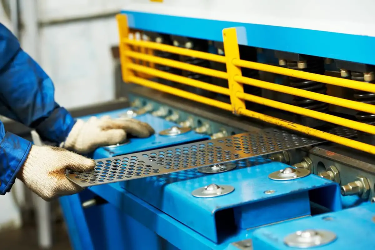
To adjust the level of the worktable, remove the platen with the steel ball in the middle of the worktable, place the level horizontally on the two convex machining surfaces of the worktable, and adjust the transverse level of the machine with the left and right support screws at the front of the machine.
Then place the level vertically and adjust the longitudinal level of the machine with the left and right support screws at the back of the machine.
The horizontal and longitudinal levels should be controlled within 1000:0.2mm.
Attention:
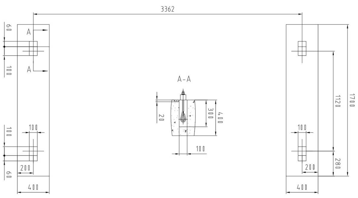
Technical Requirements:


