Imagine unlocking the precision of machine tools with a simple glass surface. Linear grating scales do just that, transforming fine lines into highly accurate measurements. This article explores how these scales work, from their structure to their practical applications. You’ll discover how they amplify displacement and improve accuracy in various machining tasks. By the end, you’ll understand why these tools are essential for modern manufacturing and how they can enhance your projects’ precision and efficiency.
In the world of precision engineering, achieving the highest level of accuracy is paramount. Grating scales, often referred to as the unsung heroes of measurement, play a crucial role in this quest for perfection. These sophisticated devices, including grating rulers and linear scales, are indispensable in various applications, from CNC machining to milling, grinding, and lathe operations. But what exactly makes grating scales so vital, and how can they be properly maintained to ensure they deliver the precision they promise?
This article delves into the fascinating realm of grating scales, unraveling their technical intricacies and exploring their diverse applications. You’ll discover how different materials like steel, glass, and ceramics contribute to the functionality of these scales and understand the nuances of accuracy grades that define their performance. Additionally, we’ll provide practical tips on maintaining and caring for your grating scales to keep them in optimal condition, ensuring they continue to deliver precise measurements.
Whether you’re an engineer seeking to enhance your CNC machine’s accuracy or a technician looking for maintenance advice, this comprehensive guide will equip you with the knowledge you need. Join us as we explore the essential aspects of grating scales, shedding light on how they enhance precision in various industries and helping you make informed decisions for your specific needs.
Grating scales function based on optical interference and diffraction principles. They consist of finely spaced lines, or gratings, which interact with light to create measurable patterns. These patterns are analyzed to determine precise positions.
When light passes through or reflects off the grating, it is diffracted into several beams, with the angles and intensities of these beams depending on the grating line spacing and light wavelength. By measuring the phase shift or interference pattern of these beams, the scale’s position can be determined accurately.
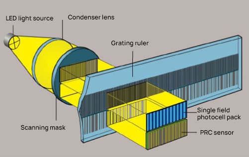
Key components include the grating ruler with finely spaced lines, a readhead sensor that moves along the ruler, a light source like LEDs or lasers for illumination, and a signal processing unit that converts readhead signals into positional data.
Grating scales come in various types, including optical, glass, and steel grating scales, each designed for specific applications.
Optical scales use light to read the grating pattern. They are known for their high precision and are commonly used in applications requiring fine measurement accuracy, such as CNC machining and laboratory instruments.
Glass grating scales incorporate gratings etched or deposited on a glass substrate. These are highly stable and provide excellent accuracy, making them suitable for high-precision applications.
Steel grating scales feature gratings engraved on a steel substrate. They are robust and suitable for harsh industrial environments.
Grating scales are categorized by accuracy grades, which indicate their precision and resolution.
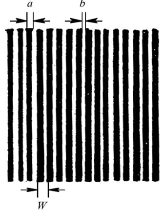
Grating – many small stripes (engraved lines) of equal distance and alternating brightness and darkness are uniformly engraved on a coated glass surface.
a – is the width of the grating lines (non-transparent)
b – is the space width between grating lines (transparent)
a+b=W grating pitch (also known as grating constant)
Usually, a=b=W/2, but it can also be engraved as a:b=1.1:0.9.
Commonly used gratings are engraved with 10, 25, 50, 100, or 250 lines per millimeter.
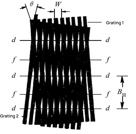
Moire Fringes – When two equal-pitch gratings (Grating 1 and Grating 2) are overlaid face to face, leaving a small gap in the middle, and the small grating angle θ is formed between the two grating lines, alternating bright and dark stripes appear in the direction close to the vertical grating line.
On the d-d line, the two grating lines overlap, and the transparent area is the largest, forming the bright band of the stripe- consisting of a series of rhombus patterns.
On the f-f line, the two grating lines are offset, forming the dark band of the stripe- consisting of some black cross-line patterns.
Moire fringe displacement measurement has the following three characteristics:
(1) Amplification effect of displacement
Stripe width BH – when the grating moves forward or backward by one grating pitch, the Moire fringes move forward or backward by one stripe width.
The Relationship between BH and θ:
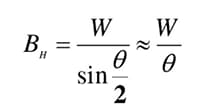
As θ decreases, BH increases. Therefore, W is amplified by 1/θ. For example, when θ=0.1°, 1/θ=573, meaning that BH is 573 times the grating pitch W. This means that the grating has a displacement amplification effect, thereby increasing the sensitivity of the measurement.
(2) Direction of Moire Fringe Movement
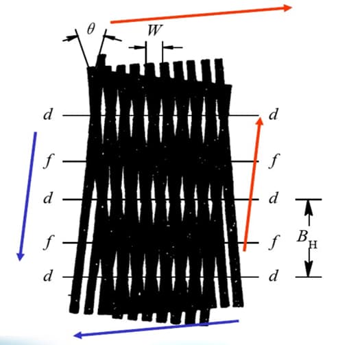
When Grating 1 moves to the right along the cutting line in a vertical direction, Moiré fringes move upwards along Grating 2’s grid lines. On the other hand, when Grating 1 moves to the left, Moiré fringes move downwards along Grating 2’s grid lines. Therefore, the direction of Grating 1’s movement can be identified as the direction of Moiré fringe movement →.
(3) The Average Effect of Error
Moiré fringes are formed by the large number of engraved lines on a grating, and they have a counteractive effect on the engraved error of the lines. This effect can significantly reduce the influence of short-period errors.
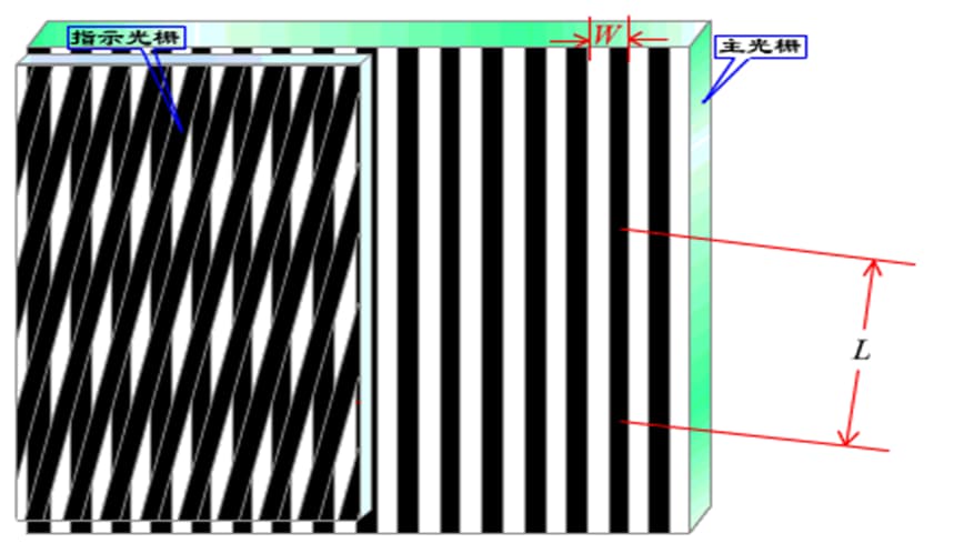
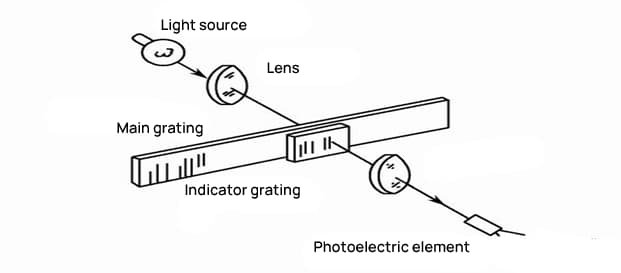
Grating Readhead: Utilizes the principle of gratings to convert the input quantity (displacement) into a corresponding electrical signal.
Components: Ruler grating, indicator grating, optical pathway system, photoelectric elements, etc.
Grating Digital Display: To discern the direction of displacement, increase measurement precision, and enable digital display, the output signal from the grating readhead must be converted into a digital signal.
Components: Shaping amplification circuit, subdivision circuit, directional discrimination circuit, and digital display circuit, etc.
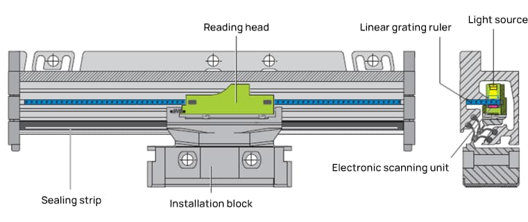
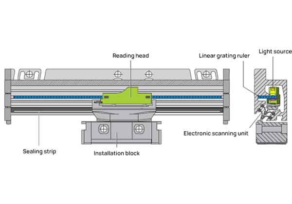
The grating ruler consists of a fixed scale body and a movable readout head.
The fixed scale body is an aluminum casing designed to protect the ruler, scanning unit, and guide rails inside from damage caused by chips, dust, or splashing water.
The movable readout head consists of a scanning unit, a precision connector, and an installation block. The precision connector connects the scanning unit to the installation block, which compensates for small mechanical errors in the guide rails.
The linear grating ruler is used to measure the position of linear axis movement. As it directly measures the mechanical position, it can accurately reflect the actual position of the machine tool.
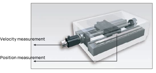
By using the linear grating ruler to measure the position of the slide, the position control loop includes all feeding mechanisms. This is the closed-loop control mode. The mechanical motion error is detected by the linear grating ruler in the sliding plate and corrected by the control system circuitry.
Therefore, it can eliminate potential errors from multiple sources:
Processing equipment: lathes, milling machines, boring machines, grinders, drilling machines, EDM machines, wire cutting, machining centers, etc.
Measurement instruments: projectors, image measuring instruments, tool microscopes, etc.
It can also compensate for errors in tool movement on CNC machine tools
Equipped with PLC for displacement measurement in various automated mechanisms.
The measurement principle of the incremental grating ruler is to modulate the light through two mutually moving gratings into Moiré fringes. By counting and subdividing the Moiré fringes, the displacement change is obtained. The absolute position is determined by setting one or more reference points on the scale grating.
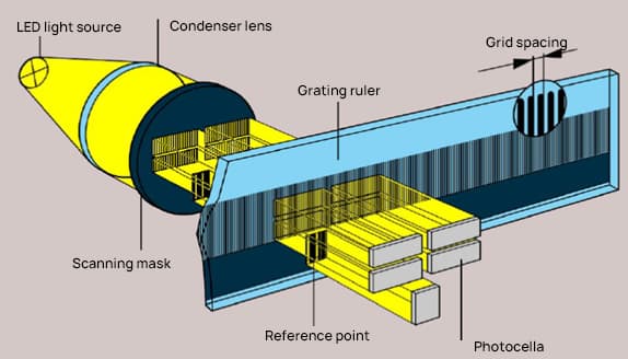
Characteristics:
The grating ruler has advantages such as a simple structure, long mechanical lifespan, high reliability, strong anti-interference capability, long transmission distance, high accuracy, and low cost.
However, incremental grating sensors also have shortcomings. Incremental grating rulers can only output the relative position of the shaft rotation.
The reference point must be set every time the power is turned off or restarted, and there is some subdivision error in the signal processing method.
The measurement principle of the absolute grating ruler is to directly encode the absolute position data in the form of codes on the grating by flickering grating lines at different widths and spacing on the grating ruler.
The subsequent electronic equipment can obtain position information while the grating ruler is powered.
Advantages:
The current position information can be obtained directly after power-on without the need for a “zeroing” operation, simplifying the control system design. Absolute position calculation is completed in the readout head without the need for subsequent subdivision circuits. The use of bidirectional serial communication technology ensures reliable communication.
The absolute position of the grating ruler is determined using reference markers (zero positions).
To shorten the distance to return to the zero position, Heidenhain designed distance-coded reference markers within the measurement length.
The absolute position of the grating ruler can be determined each time two reference markers (with a distance determined by mathematical algorithms) are passed.
Encoders with distance-coded reference points have the letter “C” after the model number (for example, LS 487C).
Single reference point

Equidistant reference points.

Distance-coded reference point/C-type.

| Signal cycle | nominal increment number | maximum displacement distance | |
| LF | 4μm | 5000 | 20 mm |
| LS | 20μm | 1000 | 20 mm |
| LB | 40μm | 2000 | 80 mm |
Non-referenced absolute linear scale

Absolute signal: Endat, Fanuc serial, Siemens, Mitsubishi, Panasonic, etc.
Incremental signal: Sine wave signal (1-Vpp signal), square wave signal (TTL signal).

1. Grating pitch:
The linear scale outputs electrical signals, and grating pitch refers to the physical grating lines on the linear scale. Every time the linear scale moves a distance equal to the grating pitch, the output electrical signal changes one cycle.
Example: When the grating pitch is 20um, if the linear scale moves a distance of 20um, the linear scale will output a sine wave with 360° phase shift and two-phase difference of 90°.
2. Signal cycle:
With the development of measuring technology, it is now possible to use frequency multiplication circuits on the linear scale reading head to multiply the sine wave generated by each grating line signal.
Therefore, the signal output cycle of the linear scale can be refined. The signal after being multiplied by the reading head is much denser than the original grating line signal, and the length of the densified signal is called the signal cycle.

If the reading head does not have frequency multiplication capability, then the grating pitch equals the signal cycle.
3. Frequency multiplication:
Frequency multiplication can be understood as densifying the original signal. Frequency multiplication can shorten the period of a sine wave, shorten the measured distance corresponding to each period, and improve the measuring accuracy.
The common frequency multiplication methods include: reading head frequency multiplication, post-multiplication instruments (provided by linear scale manufacturers, similar to preamplifiers, used for signal amplification and frequency multiplication), frequency multiplication of CNC systems, etc.
4. Measurement step:
Sine wave signals that have gone through frequency multiplication are used to measure position. Due to limitations in the manufacturing process, error level, and processing capability of the position recording circuit of the linear scale, it is impossible to infinitely multiply the original grating pitch signal.
Therefore, linear scale manufacturers have a recommended measurement step for each type of linear scale. This value refers to the minimum measured distance that the linear scale can tolerate. Within this measurement step range, the nominal measuring accuracy of the linear scale can be achieved.
Compared to CNC systems, this measurement step is usually the minimum instruction unit of the system. Similarly, this technical specification also specifies the measuring accuracy (resolution) of the linear scale.
5. Resolution:
Measuring accuracy refers to the minimum length change that the linear scale can read and output, such as 5um, 1um, 0.5um, 0.1um.
6. Measurement accuracy:
Measurement accuracy refers to the accuracy of the signal data output by the linear scale to the true length being measured.
Position error within the entire measurement range: If the maximum value of the position error established on the basis of the average value within any 1m long measurement range falls within ±a, then ±a um is the accuracy level.
In closed linear scales, this data reflects the accuracy of the linear scale, including the reading head, i.e., system accuracy. (Heidenhain: ±0.1, ±0.2, ±0.5, ±1, ±2, ±3, ±5, ±10, ±15um)
Position error within a single signal cycle:
The position deviation within a single signal cycle is determined by the grating quality, scanning quality, and signal cycle of the linear scale. The position error within a single signal cycle is usually within the range of ±2% to ±0.5% of the signal cycle.
The smaller the signal cycle, the smaller the error within a single signal cycle. This is very important for positioning accuracy during slow motion and axis movement and speed control during axis movement, which determines the surface quality and quality of the processed parts.
| The signal cycle of the scanning signal | The maximum interpolation error within a single signal cycle | |
| F L | 4μm | 0.08 μm |
| LC181 | 16μm | 0.3μm |
| LC481 | 20 μm | 0.4μm |
| LS | 20 μm | 04 μm |
| LB | 40 μm | 0.8μm |
When selecting a linear scale for precision measurement applications, several critical factors must be carefully evaluated to ensure optimal performance and compatibility with your specific requirements:
Measuring length: Determine the required measurement range, considering both the maximum travel distance and any potential future expansion needs.
Signal interface: Choose from various output options, including:
Grating pitch: Select the appropriate grating period based on the required resolution and accuracy. Smaller pitches generally offer higher precision but may have limitations in measuring length.
Measuring speed: Consider the maximum traversing speed of your application to ensure the scale can accurately track position changes at the required velocity.
Accuracy level and resolution: Determine the level of precision needed for your application, considering both the scale’s inherent accuracy and its resolution capabilities.
Space for installation position: Evaluate the available mounting space and environmental conditions to select a scale with appropriate dimensions and protection ratings.
Method of establishing reference points: Choose between incremental scales with reference marks or absolute scales, depending on your homing and referencing requirements.
Additionally, consider factors such as environmental resistance (temperature, vibration, contamination), interfacing with your control system, and long-term reliability when making your final selection.
Below are answers to some frequently asked questions:
A grating scale is a precision measurement tool used to determine position or distance with high accuracy. It operates based on the principle of diffraction or the detection of periodic transitions. In optical grating scales, a light source projects onto a grating—a periodic structure of lines or grooves—creating a pattern of light and dark areas. As the scale moves, sensors detect these transitions and convert them into electronic signals, which are then counted to determine the exact position relative to a reference point. This method allows for highly accurate and repeatable measurements, essential in applications like CNC machining, milling, grinding, and lathe operations.
Grating scales improve precision in CNC machining through several key mechanisms. They provide high-resolution measurements, often at the micron or submicron level, allowing for the accurate detection of small displacement changes in the tool or workpiece. This high resolution ensures that the machining meets stringent accuracy requirements. Additionally, grating scales offer real-time monitoring and feedback of the displacement or motion state, enabling the CNC system to promptly detect and correct any deviations. This real-time feedback forms a closed-loop control system with the CNC controller, continuously comparing actual position data with set values and making necessary adjustments to maintain precision. Advanced optical technologies used in modern grating scales enhance signal strength and interference resistance, ensuring reliable operation even in harsh environments. The robust design of these scales, including features like high-quality bearings and IP54 water and dust resistance, further contributes to their durability and reliability, reducing maintenance costs and downtime. Overall, these capabilities collectively enhance the precision and efficiency of CNC machining operations.
Common accuracy grades of grating scales include 5 microns, 3 microns, and 2 microns. The 5-micron accuracy grade is often preferred in CNC machining centers due to its balance between precision and cost. These scales are essential for high-accuracy measurements in various applications such as CNC machinery, automation systems, and metrology. The resolution of grating scales can vary, with common resolutions including 10 μm, 5 μm, 1 μm, and 0.5 μm, making them suitable for a wide range of precision tasks.
Grating scales are typically used in a variety of precise measurement and industrial applications due to their high accuracy and reliability. Key areas where grating scales are commonly employed include CNC machinery and automation, where they provide precise position data for accurate and consistent movement of machine components. They are also used in metrology for high-accuracy measurements, calibrating and verifying the precision of other measurement instruments. In industrial measurement, grating scales are crucial for linear and angular measurements in manufacturing, quality control, and research environments. Additionally, they are essential in precision engineering for achieving precise positioning and movement in the production of precision parts, robotics, and other advanced manufacturing technologies.
To maintain and clean a grating scale, follow these guidelines to ensure accuracy and longevity:
By adhering to these maintenance and cleaning practices, you can ensure your grating scales remain precise and functional for extended periods.
The differences between various types of grating scales—steel, glass, and optical—primarily lie in their materials, applications, precision requirements, and maintenance needs.
Steel grating scales are typically used in industrial settings for tasks such as flooring, stair treads, and drains. They are known for their durability and load-bearing capabilities. Steel gratings require relatively low maintenance but should be periodically cleaned and inspected for structural integrity.
Glass grating scales, often used in precision measurement tools, provide high accuracy and stability. They are less susceptible to thermal expansion compared to metal scales, making them suitable for environments where temperature changes might affect measurements. Maintenance involves careful cleaning to avoid scratches and other damage.
Optical grating scales, used in applications like spectroscopy and laser technology, are crucial for high-resolution spectral analysis. These scales can be reflective or transmissive and require extremely precise manufacturing to maintain their optical properties. They are sensitive to environmental factors such as temperature and humidity and need careful handling and storage to prevent damage.
In summary, steel grating scales are robust and used in industrial applications, glass grating scales offer high stability and precision for measurement tools, and optical grating scales provide exceptional accuracy for optical applications but require meticulous maintenance.


