Introduction
The system can record systematic machine-related deviations, but they may still occur or increase during subsequent use due to environmental factors like temperature or mechanical load. In such cases, SINUMERIK offers various compensation features.
Compensating deviations with measurements obtained using actual position encoders (such as gratings) or additional sensors (such as laser interferometers) can lead to better machining results.
This article provides an overview of SINUMERIK’s common compensation features. The practical SINUMERIK measurement cycle, such as “CYCLE996 motion measurement,” can provide comprehensive support to end-users in the continuous monitoring and maintenance of machine tools.
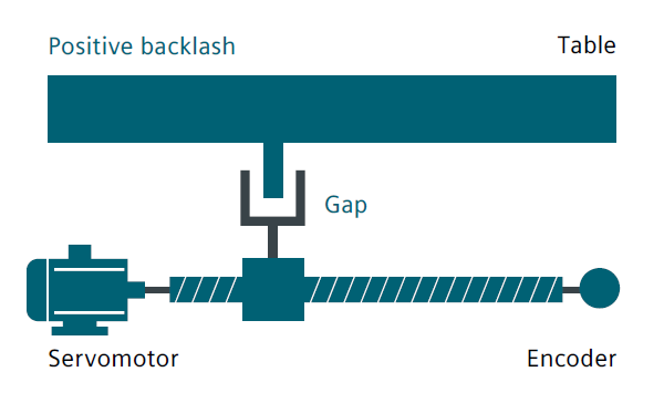
Reverse Gap Compensation
The transfer of force between moving parts and their driving components, such as ball screws, can cause discontinuity or delay. Mechanical structures without clearance significantly increase the wear and tear of the machine tool and are technically challenging to achieve.
Mechanical clearance creates a deviation between the axis/spindle path and the measured value of the indirect measurement system. This means that when the direction changes, the axis will move too far or too close, depending on the size of the clearance.
Furthermore, the work platform and its associated encoders will be affected. If the encoder is positioned ahead of the workstation, it will reach the instruction position ahead of time, shortening the actual movement distance of the machine tool.
In machine tool operations, the reverse gap compensation function can be used on the corresponding axis to automatically activate the deviation of previous records when reversing. The deviation of previous records will then be superimposed on the actual position value.
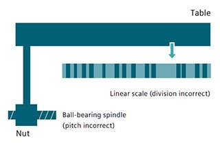
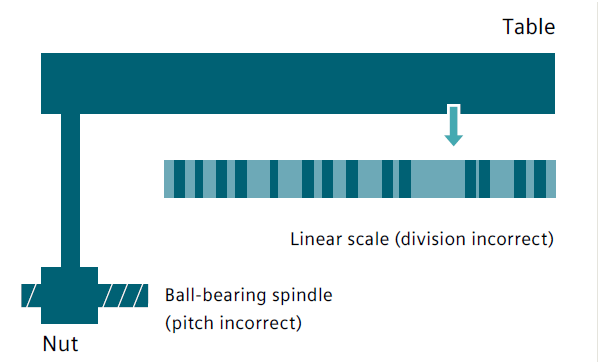
Screw pitch error compensation
The principle of indirect measurement in CNC control systems is based on the assumption that the pitch of the ball screw will remain constant within the effective travel range.
Therefore, in theory, the actual position of the straight line shaft can be deduced based on the motion information position of the driving motor.
However, the manufacturing errors of the ball screw can cause deviation in the measurement system, which is also known as screw pitch error.
Measurement bias (depending on the measuring system used) and measurement system installation error (also known as measurement system error) on the machine tool may further worsen this problem.
To compensate for these two errors, an independent measurement system, such as a laser measurement system, can be used to measure the natural error curve of CNC machines. The required compensation value can then be stored in the CNC system for later compensation.
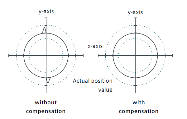
Friction compensation (quadrantal error compensation) and dynamic friction compensation
Quadrantal error compensation, also known as friction compensation, is suitable for all of the situations mentioned above, as it can significantly improve contour accuracy during circular contour processing.
The reason for this is that in quadrant conversion, one axis moves at the highest feed speed, while the other axis remains stationary. As a result, different frictional behaviors of the two axes can lead to contour errors.
Quadrant error compensation effectively reduces this error and ensures excellent machining results. The density of the compensating pulse can be set according to the characteristic curve related to acceleration, which can be determined and parameterized through roundness testing.
During roundness testing, the actual position of the circular contour and the deviation of the programming radius (especially in reversal) are quantified and displayed graphically on the man-machine interface.
In the new version of the system software, an integrated dynamic friction compensation function can dynamically compensate for the friction behavior of the machine tool under different rotational speeds. This helps to reduce actual machining contour errors and achieve higher control accuracy.
Sag and angle error compensation
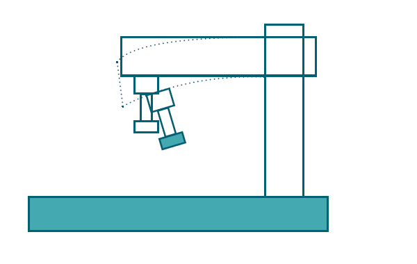
If the weight of a single part of a machine tool causes displacement and tilt of the moving part, sag compensation is required as it can cause sagging of the relevant machine parts, including the steering system.
Angle error compensation is necessary when the moving axes are not correctly aligned with each other at the right angle, such as being perpendicular.
As the zero point offset increases, the position error also increases. Both of these errors are caused by the weight of the machine tool or the weight of the tool and workpiece.
During the debugging process, the compensation values are measured, quantified, and stored in SINUMERIK in the form of a compensation table, according to the corresponding position.
When the machine is in operation, the position of the relevant axis is interpolated based on the compensation value of the storage point. For every continuous path movement, there are both basic and compensation axes.
Temperature compensation
Heat can cause the parts of a machine to expand, with the expansion range depending on the temperature and thermal conductivity of each part.
Different temperatures may lead to changes in the actual position of each shaft, which can negatively impact the accuracy of the workpiece during processing.
To offset these changes in actual values, temperature compensation can be used, where error curves of all axes at different temperatures are defined.
For correct compensation of thermal expansion, the temperature compensation value, reference position, and linear gradient angle parameters must be transferred from the PLC to the CNC control system using function blocks.
The control system automatically eliminates changes in unexpected parameters, preventing machine tool overload and activating the monitoring function.
Space error compensation system (VCS)
Systematic geometric errors of rotating and turret heads may occur due to the position of the rotating shaft, mutual compensation, and tool orientation errors. Moreover, small errors can also occur in the guiding system of the feed shaft in each machine tool.
Linear positional errors occur for linear axes, whereas rotating shafts can have horizontal and vertical straightness errors, as well as pitch, yaw, and roll angle errors. Other errors may also occur when aligning the components of the machine tool, such as vertical error.
In a three-axis machine tool, there could be 21 geometric errors at the tip, which include six error types per linear axis multiplied by three axes, plus three angle errors. These deviations collectively form a total error, also known as spatial error.
Spatial error is the deviation between the tool midpoint (TCP) position of the actual machine tool and that of an ideal, error-free machine tool. The SINUMERIK solutions partner can determine spatial errors using laser measurement equipment. However, it is necessary to measure the error of all machine tools in the entire machining space, rather than just a single position.
It is essential to record the measured values of all positions and plot the curve since the magnitude of each error depends on the position of the relevant feed axis and the measured position. Even when the Y-axis and the Z-axis are at almost the same position on the X-axis, the bias that results in the X-axis can differ when they are in different positions.
With the help of “CYCLE996 – motion measurement,” determining the rotation axis error only takes a few minutes. This means that the machine tool’s accuracy can be continuously checked and corrected, if necessary, even during production.
Deviation compensation (dynamic feedforward control)
Deviation refers to the difference between the position controller and the standard when the machine axis is moving.
Shaft deviation is the difference between the target and actual positions of the machine tool shaft.
Deviation can result in unnecessary contour errors, especially when the contour curvature changes, such as with circular or square contours.
To reduce speed-related bias to zero along the path, use the NC advanced language command FFWON in the part program.
Through feedforward control, precision of the path can be improved, resulting in better machining effects.
FFWON activates the feedforward control command.
FFWOF turns off the feedforward control command.
Electronic counterweight compensation
In extreme cases, the electronic counterweight function can be activated to prevent shaft sagging from damaging the machine tools, tools, or workpieces.
In load shafts without mechanical or hydraulic counterweights, the vertical shaft can unexpectedly sag once the brake is released.
By activating the electronic counterweight, it can compensate for the unexpected droop of the shaft. The constant balance torque maintains the position of the drooping shaft after the brake is released.