After working for a while, it’s inevitable to conduct interviews for new hires. Today, I’d like to share some questions that I commonly ask when interviewing mechanical engineers. Everyone can reflect on these questions and consider whether they represent your abilities and level.
What kind of questions would be asked in a mechanical engineering interview?
Firstly, I would ask what aspects they excel in, then proceed to ask questions from the following categories: transmission, structure, sheet metal, shaft components, plate components, and knowledge on material selection (various types of steel, aluminum, alloys, and other metals, as well as non-metallic materials like plastics), heat treatment of parts, electroplating, painting, and other surface treatments.
For transmissions, questions would focus on several aspects: gear transmission, chain drive, belt wheel, synchronous belt drive.
1. Can you provide an example of the application of dimensional chains?
Dimensional chains play a crucial role in precision manufacturing and assembly processes. They represent a series of interconnected dimensions that form a closed loop, arranged in a specific sequence to achieve desired tolerances and fits. Each individual dimension within this chain is referred to as a link.
In a dimensional chain, the critical dimension that indirectly ensures the overall accuracy of the assembly or machining process is known as the closing link. This link is typically the functional requirement or the design specification that must be met. The remaining dimensions that contribute to achieving the closing link are called constituent links.
A practical example of dimensional chain application can be found in the assembly of a cylindrical roller bearing into a housing:
- Closing link: The critical functional requirement is the bearing’s axial clearance, which must fall within a specified range for optimal performance.
- Constituent links: These include:
- Housing bore diameter
- Bearing outer ring diameter
- Bearing width
- Housing shoulder-to-shoulder distance
- Thickness of any shims or spacers used
By analyzing the dimensional chain, engineers can:
- Determine the required tolerances for each constituent link to achieve the desired axial clearance (closing link).
- Identify which dimensions have the most significant impact on the final assembly accuracy.
- Optimize the manufacturing processes for critical components.
- Develop effective quality control measures for key dimensions.
- Predict the cumulative effect of individual tolerances on the overall assembly.
This approach enables manufacturers to:
- Enhance product quality and reliability
- Reduce assembly issues and rework
- Optimize material usage and production costs
- Improve overall manufacturing efficiency
2. What are the common types of ferrous metal materials? What is high-quality carbon steel?
Ferrous metals primarily encompass steel and cast iron, with steel being further categorized into carbon steel and alloy steel. This classification is based on the composition and properties of the metal.
Carbon steel, a fundamental category, is subdivided into three grades based on the content of impurities, particularly sulfur (S) and phosphorus (P):
- Ordinary carbon steel
- High-quality carbon steel
- Advanced carbon steel
High-quality carbon steel is distinguished by its stringent control of impurities, specifically maintaining sulfur and phosphorus levels at or below 0.040% each. This low impurity content significantly enhances the steel’s mechanical properties, including improved strength, ductility, and weldability.
The controlled composition of high-quality carbon steel offers several advantages:
- Enhanced formability and machinability
- Improved surface finish quality
- Better response to heat treatment
- Increased resistance to crack propagation
- Superior weldability and reduced risk of hot cracking
These characteristics make high-quality carbon steel an excellent choice for applications requiring precise tolerances, high strength-to-weight ratios, and reliable performance under various loading conditions. Common applications include automotive components, precision machinery parts, and high-performance structural elements.
It’s important to note that while the ≤0.040% threshold for S and P is a general guideline, specific standards may vary slightly depending on the exact grade and intended application of the steel.
3. How can welding stress be eliminated in a welded part?
Welding stress, also known as residual stress, can be mitigated through various methods, each with specific applications and effectiveness:
1. Heat Treatment:
- Post-Weld Heat Treatment (PWHT): This widely adopted method involves controlled heating and cooling of the welded part. It can be applied as:
a) Overall heat treatment: The entire component is subjected to a specific temperature cycle.
b) Local heat treatment: Focused heating is applied to the weld area and its immediate surroundings.
- Stress Relief Annealing: A common form of PWHT where the part is heated to a temperature below the material’s critical point, held for a specified time, then slowly cooled.
- Normalizing: Heating the material above its critical temperature followed by air cooling, particularly effective for carbon steels.
2. Mechanical Methods:
- Peening: Controlled hammering of the weld surface to induce compressive stress, counteracting tensile residual stress.
- Shot Peening: Bombarding the surface with small metallic or ceramic particles to create a uniform compressive stress layer.
- Rolling: Applying pressure to the weld surface using rollers, effective for long, straight welds.
3. Vibrational Stress Relief (VSR):
- Subjecting the welded part to controlled vibrations at specific frequencies to redistribute internal stresses.
- Non-thermal method suitable for parts where heat treatment is impractical or could cause distortion.
4. Natural Aging:
- Allowing the welded part to stabilize at room temperature over time.
- Generally less effective than active methods but can be suitable for non-critical applications.
5. Controlled Welding Techniques:
- Back-step welding: Welding in short segments in a direction opposite to the overall progress.
- Balanced welding: Distributing weld metal evenly around the neutral axis of the joint.
- Pre-setting: Positioning parts to counteract anticipated distortion.
6. Cryogenic Treatment:
- Cooling the welded part to extremely low temperatures (typically using liquid nitrogen) followed by gradual return to room temperature.
- Particularly effective for certain tool steels and high-alloy materials.
4. What are the commonly used heat treatment methods? (Name at least three) What is tempering?
The commonly used heat treatment methods for metals include annealing, normalizing, quenching, tempering, and case hardening, among others. Each of these processes serves specific purposes in altering the mechanical properties and microstructure of metals.
Tempering is a critical heat treatment process typically performed after quenching. It involves reheating the quenched metal to a temperature below its lower critical temperature, usually between 150°C to 650°C (302°F to 1202°F), holding it at that temperature for a specified time, and then cooling it, usually in air. The primary purposes of tempering are:
- To reduce internal stresses induced during quenching
- To increase ductility and toughness
- To achieve a desired balance between hardness and ductility
High-temperature tempering, conducted in the range of 500-650°C (932-1202°F), is particularly effective for steels. This process allows for significant stress relief and microstructural changes, resulting in a good combination of strength, ductility, and toughness. The exact tempering temperature and duration depend on the specific alloy composition and the desired final properties.
It’s important to note that tempering parameters must be carefully controlled, as they significantly influence the final mechanical properties of the metal. The time-temperature relationship in tempering is crucial, and modern heat treatment facilities often use precise computer-controlled processes to ensure consistent results.
5. What are the primary failure modes of closed gear (soft and hard tooth surface) transmission? What is the principle of design verification?
The primary failure modes of closed gear transmissions differ significantly between soft and hard tooth surface gears, necessitating distinct approaches to design and verification:
For closed soft tooth surface gear transmission:
The predominant failure mode is pitting fatigue on the tooth surface. This occurs due to repeated high-stress contact between mating gear teeth, causing microscopic surface and subsurface cracks that eventually lead to material removal. The design process should prioritize:
- Calculation based on the tooth surface contact stress formula:
σH ≤ [σH]
Where σH is the calculated contact stress and [σH] is the allowable contact stress.
- Verification using the tooth root bending fatigue strength formula:
σF ≤ [σF]
Where σF is the calculated bending stress and [σF] is the allowable bending stress.
For closed hard tooth surface gear transmission:
The main failure mode shifts to tooth root fatigue fracture. This occurs due to cyclic bending stresses at the tooth root, eventually leading to crack initiation and propagation. The design process should focus on:
- Calculation based on the tooth root bending fatigue strength formula:
σF ≤ [σF]
- Verification using the tooth surface contact stress formula:
σH ≤ [σH]
Design verification principles:
- Material selection: Choose appropriate materials and heat treatments to achieve the required surface hardness and core strength.
- Geometry optimization: Consider factors such as tooth profile modifications, root fillet radius, and face width to distribute stresses effectively.
- Lubrication: Ensure proper lubrication to minimize friction and wear, particularly crucial for soft tooth surface gears.
- Load analysis: Account for dynamic loads, shock loads, and load distribution across the face width.
- Safety factors: Apply appropriate safety factors to account for uncertainties in loading, manufacturing tolerances, and material properties.
- Consideration of other failure modes: While focusing on the primary failure modes, also evaluate secondary modes such as scuffing, wear, and plastic deformation.
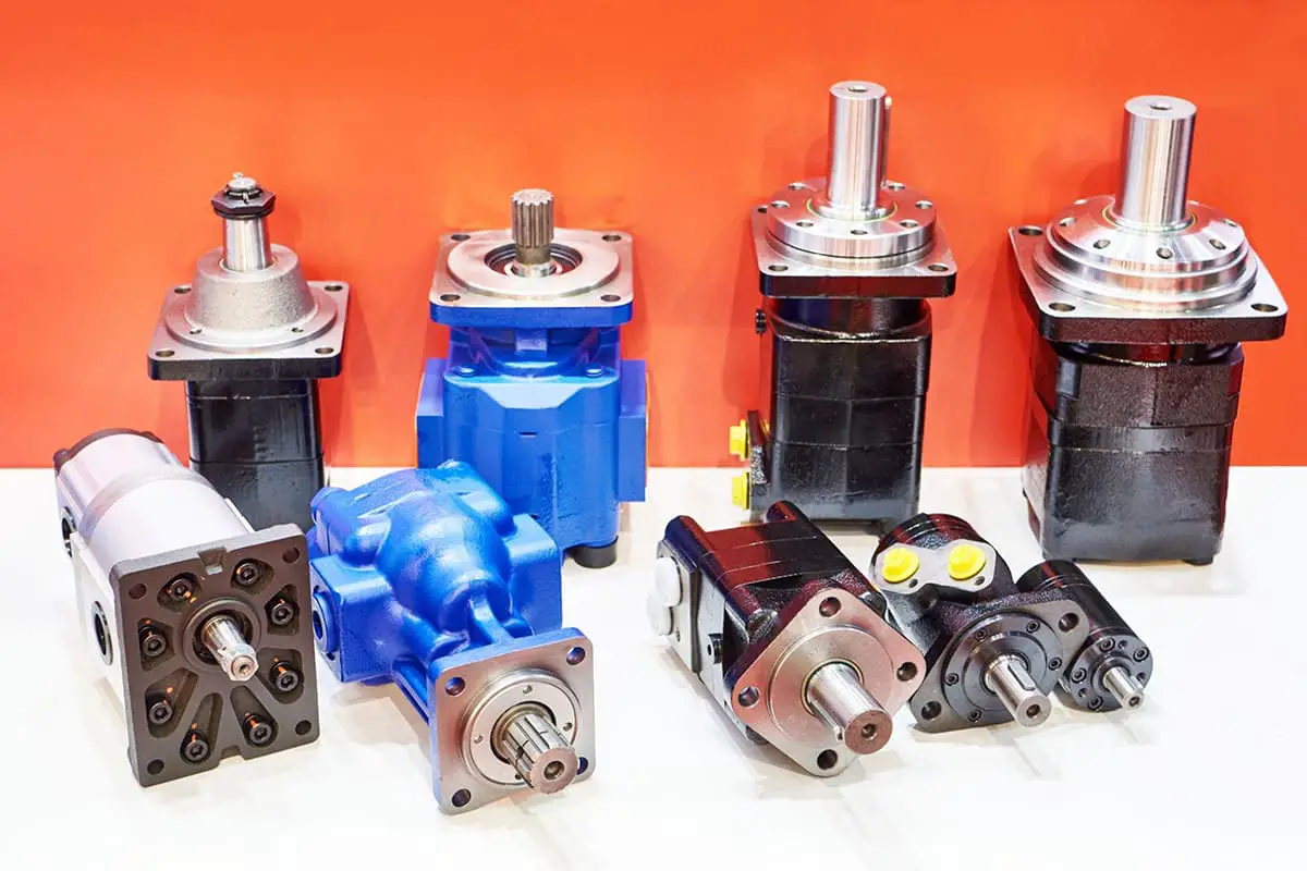
6. What is the function of a gearbox?
A gearbox, also known as a transmission, serves as a crucial mechanical component that modifies the speed and torque transmitted from the prime mover (such as an engine or electric motor) to the driven machine or mechanism. Its primary functions include:
- Speed modification: Gearboxes can increase or decrease the rotational speed between the input and output shafts, allowing for optimal operational speeds of both the power source and the driven equipment.
- Torque conversion: By altering the gear ratios, a gearbox can increase or decrease the torque output, matching the power source’s characteristics to the load requirements of the driven machinery.
- Power distribution: In some applications, gearboxes can split power between multiple output shafts or combine power from multiple input sources.
- Rotational direction change: Gearboxes can reverse the direction of rotation when required by the application.
Gearboxes come in various types and configurations, including:
- Mechanical gearboxes: These use a system of gears and shafts to achieve the desired speed and torque modifications. Common types include spur, helical, bevel, and worm gearboxes.
- Fluid coupling systems: These use hydraulic fluids to transmit power, offering smooth power transfer and inherent overload protection. Examples include torque converters and hydrostatic transmissions.
- Fixed speed ratio gearboxes: These maintain a constant ratio between input and output speeds, suitable for applications with consistent load requirements.
- Variable speed ratio gearboxes: These allow for changing the speed ratio during operation, providing flexibility for applications with varying load demands. Examples include continuously variable transmissions (CVTs) and infinitely variable transmissions (IVTs).
7. What industrial process are you most familiar with? For instance, ironmaking, steelmaking, or rolling.
I am most familiar with the medium-thick plate rolling process in steel production. This advanced manufacturing process transforms continuous cast billets into high-quality steel plates through a series of precisely controlled operations. The production flow typically consists of the following key stages:
- Continuous casting billet: The process begins with solidified steel billets from continuous casting, ensuring consistent quality and dimensional accuracy.
- Heating furnace: Billets are heated to optimal rolling temperatures (typically 1150-1250°C) in computer-controlled walking beam furnaces, ensuring uniform heat distribution and energy efficiency.
- Descaler: High-pressure water jets remove surface oxides, improving surface quality and reducing potential defects.
- Rolling mill: The heart of the process, where heated billets pass through a series of stands with hydraulically controlled rolls. This stage employs advanced technologies such as automatic gauge control (AGC) and work roll bending to achieve precise thickness tolerances and flatness.
- Controlled cooling: Plates undergo accelerated cooling using water sprays or laminar cooling systems, allowing for precise microstructure control and enhanced mechanical properties.
- Straightening: Hot levelers or cold leveling machines correct any flatness deviations, ensuring dimensional accuracy.
- Cooling bed: Plates are cooled to ambient temperature under controlled conditions to prevent distortion.
- Cut to length: Plates are precisely cut to customer-specified dimensions using high-speed shears or plasma cutting systems.
- Side shears and length shears: Edge trimming and final length adjustments are made to meet exact dimensional requirements.
- Surface inspection and cleaning: Automated vision systems and trained inspectors examine plates for surface quality, with any detected imperfections addressed through grinding or other remediation techniques.
- Stacking: Plates are sorted and stacked according to customer orders and specifications.
- Storage and delivery: Finished plates are stored in climate-controlled environments before being shipped to customers via rail, truck, or marine transport.
This process leverages advanced automation, real-time quality control systems, and data analytics to ensure consistent production of high-quality medium-thick plates meeting diverse industrial applications’ stringent requirements.
8. In the most extreme scenario, what could happen to a hydraulic cylinder subjected to a strong external shock?
In the most extreme scenario, a hydraulic cylinder subjected to a strong external shock could experience catastrophic failure, potentially leading to:
1. Cylinder detachment: The intense force could cause the cylinder to break free from its mountings, resulting in a complete loss of function and posing significant safety risks.
2. Oil pipe rupture: High-pressure hydraulic lines may burst or rupture, causing rapid loss of hydraulic fluid and system pressure. This can lead to oil leakage, environmental contamination, and potential fire hazards if the fluid comes into contact with hot surfaces.
3. Structural deformation: The cylinder body, piston rod, or internal components may undergo severe deformation, bending, or fracturing. This can result in:
- Misalignment of internal components
- Scoring or gouging of the cylinder bore
- Seal failure and subsequent fluid leakage
- Compromised structural integrity, potentially leading to explosive failure under pressure
4. Internal component damage: Shock forces may cause damage to internal parts such as:
- Piston head separation from the rod
- Bearing or bushing failure
- Valve malfunction in servo-hydraulic systems
5. Pressure spike: A sudden shock could create a pressure surge within the system, potentially exceeding the cylinder’s pressure rating and causing additional damage to other hydraulic components.
6. Secondary damage: The failure of the hydraulic cylinder could lead to collateral damage in connected machinery or structures, potentially causing a chain reaction of failures in the wider system.
To mitigate these risks, proper shock absorption systems, robust mounting designs, and regular inspections are crucial for hydraulic systems operating in high-shock environments. Additionally, incorporating safety features such as pressure relief valves and designing with appropriate safety factors can help prevent catastrophic failures in extreme scenarios.
9. When checking a part under combined bending and torsional loads, which strength theory should be chosen?
For parts subjected to combined bending and torsional loads, the von Mises yield criterion (also known as the distortion energy theory or the third strength theory) is most appropriate. This theory provides a comprehensive assessment of the stress state in the material, considering the interaction between normal and shear stresses.
The procedure involves:
- Calculate the bending stress (σ) and torsional shear stress (τ) separately.
- Apply the von Mises equation to determine the equivalent stress (σeq): σeq = √(σ² + 3τ²)
- Compare the equivalent stress to the material’s yield strength, ensuring: σeq ≤ [σ], where [σ] is the allowable stress
This approach accounts for the multi-axial stress state and provides a more accurate prediction of material failure under complex loading conditions than using individual stress components alone. It’s particularly useful for ductile materials and is widely adopted in engineering practice for its reliability and ease of application.
10. What is the development trend of modern mechanical machining?
The development of modern mechanical machining is characterized by a multifaceted evolution towards advanced manufacturing systems. This progression is driven by several key trends:
- Enhanced Precision: Advancements in machine tool technology, metrology, and process control are pushing the boundaries of achievable tolerances and surface finishes. Ultra-precision machining techniques, such as diamond turning and ion beam figuring, are enabling the production of components with nanometer-level accuracy.
- Increased Integration: The convergence of various manufacturing technologies is leading to hybrid machining processes. For instance, the combination of additive manufacturing with traditional subtractive methods allows for complex geometries and optimized material usage.
- Improved Flexibility: Adaptive manufacturing systems and reconfigurable machine tools are becoming more prevalent, allowing for rapid changeovers and customization in production. This trend is supported by modular tooling systems and universal fixturing solutions.
- Expanded Networking: The implementation of Industrial Internet of Things (IIoT) and cloud computing is facilitating real-time data exchange between machines, systems, and operators. This connectivity enables predictive maintenance, remote monitoring, and data-driven process optimization.
- Advanced Virtualization: Digital twins and sophisticated simulation software are revolutionizing process planning and optimization. Virtual commissioning and augmented reality tools are streamlining machine setup and operator training.
- Enhanced Intelligence: Artificial Intelligence (AI) and Machine Learning (ML) algorithms are being integrated into CNC controllers and CAM systems. These technologies enable adaptive control, autonomous decision-making, and continuous process improvement.
- Improved Cleanliness: Environmental concerns and stringent regulations are driving the development of cleaner machining processes. This includes the adoption of minimum quantity lubrication (MQL), cryogenic cooling, and dry machining techniques, as well as more efficient chip and coolant management systems.
- Sustainable Manufacturing: There is an increasing focus on energy efficiency, waste reduction, and the use of sustainable materials. This trend is reflected in the development of eco-friendly cutting fluids, energy-regenerative machine components, and lifecycle-oriented machine designs.
11. What is the approximate carbon content in 45# steel?
The carbon content in 45# steel typically ranges from 0.42% to 0.50%. This medium carbon steel, also known as C45 in some international standards, is commonly referred to as 45 steel in the Chinese GB (Guobiao) standard system. The “45” in its designation directly indicates its approximate carbon content of 0.45%.
This versatile steel grade, sometimes called “oil steel” due to its suitability for oil quenching, offers a good balance of strength, hardness, and ductility. It is widely used in various engineering applications, particularly for components requiring moderate strength and wear resistance.
In the market, 45# steel is primarily available as hot-rolled products, which are suitable for a wide range of applications. Cold-rolled specifications are also available, typically in thicknesses ranging from 1.0 to 4.0mm. The cold-rolling process imparts improved surface finish and tighter dimensional tolerances, making it ideal for applications requiring better machinability or surface quality.
12. What are some common casting defects?
Casting defects can significantly impact the quality, performance, and reliability of metal components. The most prevalent defects encountered in metal casting processes include:
- Porosity: This includes both gas porosity (blowholes) and shrinkage porosity. Gas porosity results from trapped gases during solidification, while shrinkage porosity occurs due to inadequate feed metal during cooling.
- Inclusions: These are foreign particles, often sand or slag, embedded in the casting. Sand inclusions are particularly common in sand casting processes.
- Misruns and cold shuts: Misruns occur when the molten metal fails to completely fill the mold cavity. Cold shuts happen when two flows of metal meet but fail to fuse properly.
- Hot tears and cracks: These are separations in the casting caused by stresses during solidification. Hot tears occur at high temperatures, while cracks can form during or after cooling.
- Surface defects: These include sand adhesion, where sand from the mold sticks to the casting surface, and scabs, which are rough, irregularly shaped protrusions on the casting surface.
- Dimensional inaccuracies: These can result from issues like pattern shift, mold wall movement, or excessive shrinkage during cooling.
- Metallurgical defects: These include problems like segregation (uneven distribution of alloying elements) and hot spots (areas of the casting that solidify last and may have different properties).
13. What is the role of cutting fluid in metal cutting processes?
Cutting fluid plays a crucial role in metal cutting processes, serving multiple essential functions that significantly enhance machining performance and tool life. The primary purposes of cutting fluid include:
- Cooling: Cutting fluid dissipates heat generated during the cutting process, reducing thermal damage to both the workpiece and cutting tool. This temperature control helps maintain dimensional accuracy and prevents premature tool wear.
- Lubrication: By reducing friction between the cutting tool, chip, and workpiece, cutting fluid minimizes energy consumption and heat generation. This lubrication effect is particularly important in low-speed cutting operations and when machining ductile materials.
- Chip removal: Cutting fluid aids in flushing away metal chips and debris from the cutting zone, preventing re-cutting of chips and ensuring a clean cutting surface. This function is critical for maintaining cut quality and preventing tool damage.
- Corrosion prevention: Many cutting fluids contain rust inhibitors that protect both the workpiece and machine components from oxidation and corrosion, especially important for ferrous materials.
- Improved surface finish: The cooling and lubrication properties of cutting fluid contribute to a better surface finish on the workpiece, often reducing the need for secondary finishing operations.
- Extended tool life: By reducing friction and heat, cutting fluid significantly prolongs the life of cutting tools, leading to reduced tooling costs and improved productivity.
- Higher cutting speeds: The cooling and lubrication effects allow for increased cutting speeds and feed rates, enhancing overall machining efficiency.
## 14. Give an example of what digital design entails.
Digital design encompasses the comprehensive integration of advanced technologies throughout the entire product lifecycle, from conceptualization to production and beyond. It leverages powerful computational tools and methodologies to revolutionize traditional design processes.
For instance, in the context of metal fabrication, digital design might involve:
- 3D CAD Modeling: Creating precise, parametric 3D models of components using software like SolidWorks or Autodesk Inventor. These models serve as the digital foundation for all subsequent processes.
- Simulation and Analysis: Utilizing Finite Element Analysis (FEA) to simulate structural integrity, thermal behavior, or fluid dynamics, optimizing designs before physical prototyping.
- Generative Design: Employing AI-driven algorithms to explore thousands of design iterations based on specific constraints and performance criteria, often resulting in innovative, lightweight structures.
- Digital Twin Creation: Developing virtual replicas of physical products or processes, enabling real-time monitoring, predictive maintenance, and performance optimization.
- Integrated Product Data Management (PDM): Implementing systems to manage all product-related data, ensuring version control, collaboration, and traceability throughout the design process.
- Computer-Aided Manufacturing (CAM): Translating 3D models directly into machine instructions for CNC machining, additive manufacturing, or robotic welding systems.
- Virtual Reality (VR) Prototyping: Using VR technologies for immersive design reviews, ergonomic assessments, and virtual assembly planning.
15. What does informatization in manufacturing include?
Informatization in manufacturing encompasses the comprehensive integration and utilization of advanced digital, intelligent, and networked information technologies to transform traditional industrial paradigms. This revolution spans across multiple domains:
- Design: Implementation of Computer-Aided Design (CAD), simulation software, and digital twins for rapid prototyping and optimization.
- Manufacturing Technologies: Adoption of Computer-Integrated Manufacturing (CIM), Industrial Internet of Things (IIoT), and Artificial Intelligence (AI) for smart production lines and predictive maintenance.
- Business Strategies: Leveraging Big Data analytics and cloud computing for market analysis, supply chain optimization, and customer relationship management.
- Management Models: Utilizing Enterprise Resource Planning (ERP) systems, Manufacturing Execution Systems (MES), and digital dashboards for real-time decision-making and lean management practices.
This digital transformation enables manufacturers to:
- Enhance product quality and consistency through data-driven process control
- Increase operational efficiency and reduce waste
- Improve flexibility and responsiveness to market demands
- Foster innovation in product development and customization
16. What are the differences between rolling bearings and sliding bearings? Where are they each used?
Rolling bearings offer high precision operation and can accommodate both radial and axial loads simultaneously. They require less lubricant, are easier to install, and exhibit lower friction coefficients compared to sliding bearings. Their standardized, serialized, and universal design facilitates convenient use, maintenance, and cost-effectiveness, eliminating the need for expensive non-ferrous metals often required in sliding bearings.
However, rolling bearings are highly susceptible to contamination from foreign particles such as metal debris. They generally have a shorter service life than sliding bearings and lower load-bearing capacities relative to their size, resulting in larger radial dimensions.
Sliding bearings excel in applications demanding high load capacity, compact size, and structural integrity. They are commonly employed in crankshaft bearings of internal combustion engines and rolling mill bearings. These bearings offer superior damping characteristics, making them ideal for precision applications with stringent vibration and noise requirements.
The selection between rolling and sliding bearings depends on specific application criteria:
- Rolling bearings are preferred for:
- High-speed operations
- Applications requiring low starting torque
- Situations where frequent starts and stops occur
- Environments with minimal contamination risk
- Sliding bearings are advantageous for:
- Heavy load-bearing applications
- Shock and vibration absorption
- Space-constrained designs
- Corrosive or contaminated environments
In practice, hybrid solutions combining both bearing types are sometimes employed to leverage the strengths of each. For instance, in large industrial gearboxes, rolling bearings might be used for high-speed shafts, while sliding bearings support slower, more heavily loaded components.
17. What is the meaning of CNC?
CNC stands for Computer Numerical Control. It refers to a manufacturing process where pre-programmed computer software dictates the movement of factory tools and machinery. CNC systems automate the control of machine tools through the use of software embedded in a microcomputer attached to the tool. This technology enables precise control of various parameters such as feed rate, coordination, location, and speed, allowing for highly accurate and repeatable machining operations.
CNC technology is widely used in modern manufacturing for a variety of applications, including:
- Milling and turning operations
- Laser cutting and plasma cutting
- 3D printing and additive manufacturing
- Welding and fabrication
- Electrical discharge machining (EDM)
The use of CNC machines has revolutionized the manufacturing industry by improving precision, efficiency, and consistency in production processes, while also reducing human error and labor costs.
18. What are the differences between DC motors and AC motors?
DC motors utilize a stationary magnetic field with a rotating conductor, while AC motors employ a rotating magnetic field with a stationary conductor. This fundamental difference in design leads to distinct operational characteristics and applications.
Speed control is a key differentiator. DC motors excel in this aspect, offering precise speed adjustment by varying the input voltage or current. This makes them ideal for applications requiring fine speed control, such as in robotics or electric vehicles. AC motors, conversely, typically adjust speed by altering the frequency of the alternating current, often through variable frequency drives (VFDs).
Torque characteristics also differ significantly. DC motors generally provide higher starting torque and better torque-to-speed ratios, especially at low speeds. This makes them superior for applications requiring high torque at low RPMs, such as in conveyor systems or electric traction. AC motors, particularly induction types, tend to have lower starting torque but can maintain consistent torque over a wider speed range.
Maintenance requirements vary between the two. DC motors, with their commutator and brush assembly, typically require more frequent maintenance due to brush wear and commutator degradation. AC motors, especially brushless designs, generally offer lower maintenance needs and higher reliability over time.
Efficiency and power density also differ. Modern AC motors, particularly those using permanent magnets, often achieve higher efficiency and power density compared to equivalent DC motors. This has led to increased adoption of AC motors in industrial applications and electric vehicles where energy efficiency is crucial.
Cost considerations play a role in motor selection. DC motors are often simpler and less expensive for low-power applications. However, for high-power industrial uses, AC motors frequently prove more cost-effective due to their robustness and lower maintenance requirements.
The choice between DC and AC motors ultimately depends on the specific application requirements, including speed control precision, torque needs, efficiency goals, maintenance capabilities, and overall system design considerations.
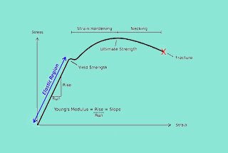
19. What is the difference between elastic and plastic deformation in metal materials?
In metal materials, elastic deformation refers to a reversible change in shape that occurs when an external force is applied within the material’s elastic limit. Upon removal of the applied stress, the metal returns to its original dimensions without permanent alteration to its crystalline structure. This behavior is governed by Hooke’s Law, where stress is proportional to strain up to the yield point.
Plastic deformation, conversely, is an irreversible change in shape that takes place when the applied stress exceeds the material’s yield strength. This permanent deformation is characterized by the breaking and reforming of atomic bonds, resulting in a rearrangement of the metal’s crystal structure. Unlike elastic deformation, plastic deformation persists even after the removal of the applied force.
In engineering applications, plastic deformation is often considered a form of structural failure, particularly in load-bearing components. It can lead to changes in material properties, reduced performance, and potential safety hazards. Consequently, a primary objective in structural design is to ensure that working stresses remain well below the yield strength of the material, thus preventing plastic deformation under normal operating conditions.
However, it’s important to note that controlled plastic deformation can be advantageous in certain manufacturing processes, such as metal forming operations (e.g., forging, stamping, or extrusion), where it is deliberately induced to achieve desired shapes and properties. Understanding the transition from elastic to plastic behavior is crucial for optimizing material selection, component design, and manufacturing processes in metalworking industries.
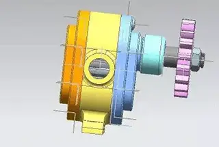
20. What is the function of a reducer?
A reducer, also known as a speed reducer or gearbox, serves to modify the rotational speed and torque transmitted from the prime mover (such as an electric motor or engine) to the driven machine or equipment. Its primary functions include:
- Speed Reduction: Decreasing the input speed to a lower output speed, typically to match the operational requirements of the driven machine.
- Torque Multiplication: Increasing the available torque at the output shaft, which is inversely proportional to the speed reduction ratio.
- Inertia Matching: Optimizing the load distribution between the prime mover and the driven machine, improving system efficiency and reducing wear.
- Power Transmission: Efficiently transferring power from the input to the output while accommodating misalignments and absorbing shock loads.
Reducers are available in various configurations:
1. Mechanical Types:
- Gear reducers (e.g., spur, helical, bevel, worm)
- Belt and pulley systems
- Chain and sprocket arrangements
2. Hydrodynamic Types:
- Fluid couplings
- Torque converters
3. Speed Ratio Options:
- Fixed ratio: Provides a constant speed reduction
- Adjustable ratio: Allows for variable speed output, often through the use of variable pitch pulleys or advanced electronic controls
The selection of the appropriate reducer type and configuration depends on factors such as power requirements, speed ranges, environmental conditions, and specific application needs.