Have you ever wondered how everyday metal objects take shape? This article uncovers 26 advanced techniques used in metal forming, from traditional methods like forging and rolling to modern innovations such as metal injection molding and selective laser melting. By exploring these diverse processes, you’ll gain insight into how raw metal is transformed into precise, durable components that power industries and daily life alike. Discover the fascinating world of metal forming and the technology that shapes our modern world.
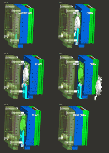
Die-casting is a sophisticated metal forming process that utilizes a precision-engineered mold cavity to apply high pressure to molten metal, resulting in complex, near-net-shape components. The molds, typically constructed from high-strength tool steels such as H13 or P20, are designed to withstand extreme temperatures and pressures. These molds share similarities with those used in injection molding, but are optimized for metalworking conditions.
The process begins with the injection of liquid metal, often aluminum, zinc, or magnesium alloys, into the mold cavity at pressures ranging from 5,000 to 30,000 psi. This high-pressure injection ensures excellent fill of intricate details and thin wall sections, while also improving the metal’s density and mechanical properties. The rapid solidification under pressure results in fine-grained microstructures, enhancing the strength and dimensional stability of the final product.
Modern die-casting operations often incorporate advanced technologies such as real-time thermal imaging for mold temperature control, vacuum-assisted systems to minimize porosity, and computer-controlled shot sleeves for precise metal dosing. These innovations contribute to improved part quality, reduced cycle times, and increased process efficiency, making die-casting a preferred method for high-volume production of complex metal components in industries ranging from automotive to consumer electronics.

Sand casting is a versatile and widely used metal forming process that involves creating a mold using specially prepared sand. The process begins with a pattern—typically a replica of the desired part made from wood, metal, or plastic—which is used to form the mold cavity. This pattern is placed in a two-part molding box, called a flask, and packed with sand that has been mixed with bonding agents to improve its cohesiveness and moldability.
The mold is created in at least two sections to facilitate pattern removal and subsequent casting. The upper section, known as the cope, and the lower section, called the drag, are separated along a parting line. Before assembling the mold, a gating system is incorporated into the sand, which includes the pouring basin, sprue, runners, and ingates. These channels direct the molten metal into the mold cavity. Additionally, risers are added to compensate for metal shrinkage during solidification, and vents are created to allow gases to escape, preventing defects in the final casting.
Once the mold is prepared, molten metal is poured into the cavity through the gating system. The metal is left to solidify and cool, a process that can vary in duration depending on the size and complexity of the part, as well as the metal alloy used. After solidification, the sand mold is broken apart to remove the casting—a process known as shakeout. The cast part then undergoes cleaning, which may involve removing excess material from the gating system, shot blasting to remove residual sand, and heat treatment to enhance mechanical properties.
Sand casting offers several advantages, including the ability to cast complex geometries, a wide range of part sizes from small components to massive industrial parts, and the flexibility to work with various metal alloys. However, it’s important to note that each casting requires a new sand mold, which can impact production efficiency for high-volume manufacturing. Modern advancements in sand casting technology, such as 3D-printed sand molds and computer-simulated mold filling and solidification, continue to improve the precision and efficiency of this time-honored metalworking process.

Investment casting, also known as lost wax casting, is a precision manufacturing process that involves the following key steps: pattern creation, shell building, dewaxing, casting, and finishing.
The process begins with the production of a high-precision wax or resin pattern of the desired part. This pattern is then dipped repeatedly into a ceramic slurry and coated with fine refractory particles to build up a robust ceramic shell. Each layer is allowed to dry before the next application, creating a multi-layered mold.
Once the ceramic shell reaches the required thickness, it undergoes a dewaxing process. The mold is placed in a steam autoclave or flash-fire oven, causing the wax to melt and evacuate through designated gates, leaving a hollow ceramic shell that perfectly replicates the original pattern’s geometry.
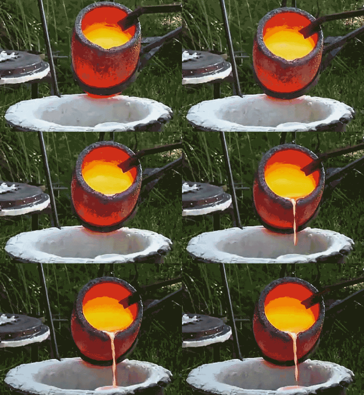
The empty ceramic mold is then preheated to specific temperatures to remove any residual moisture and to minimize thermal shock. Molten metal, typically alloys of steel, aluminum, or superalloys for high-performance applications, is then poured into the heated ceramic mold through a gating system. The metal fills the intricate cavities, replicating the original pattern’s details with high fidelity.
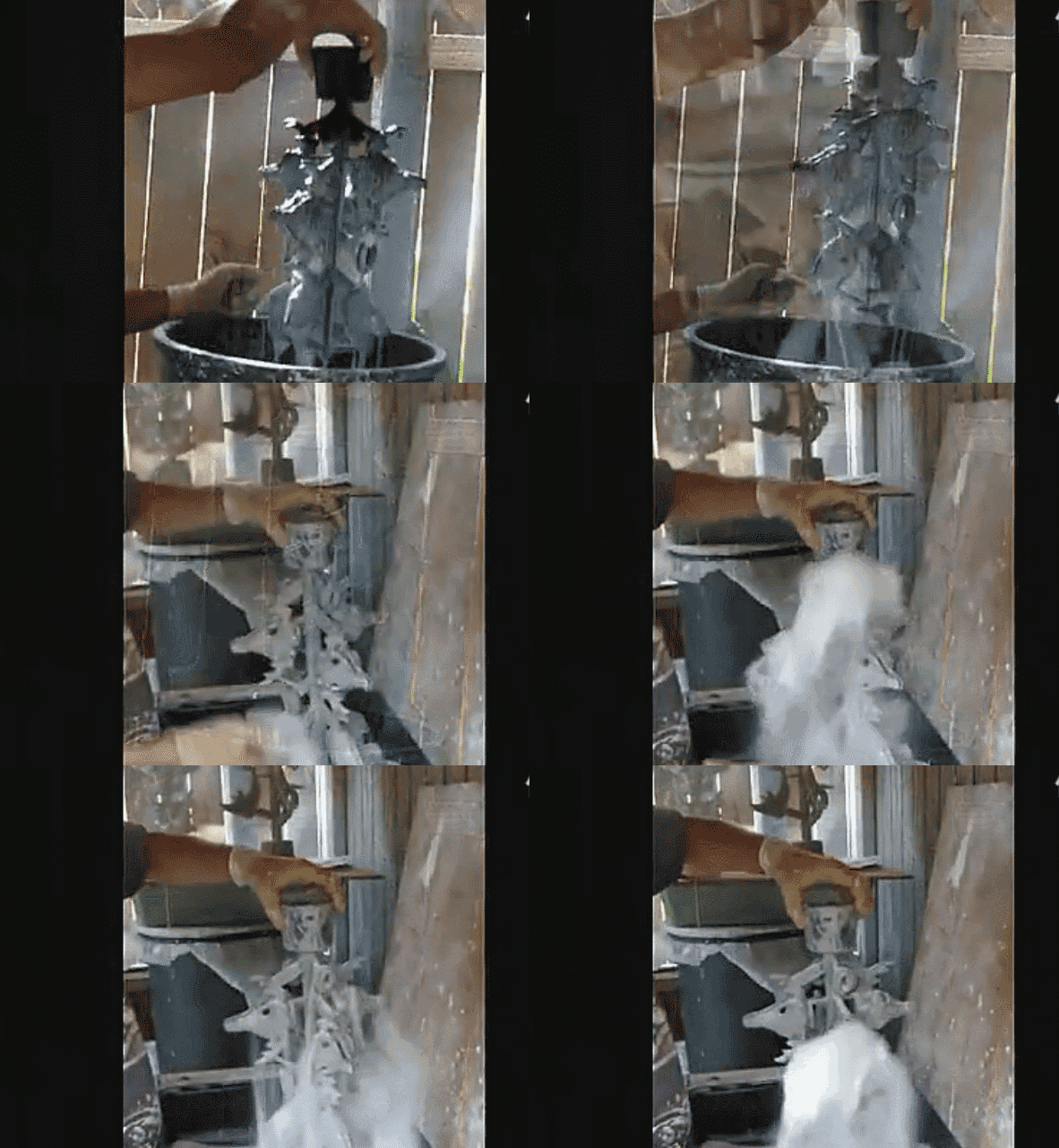
After solidification and cooling, the ceramic shell is removed through mechanical vibration or high-pressure water jets, revealing the cast part. Final operations may include cutting off the gating system, heat treatment for optimal mechanical properties, and surface finishing techniques such as grinding or polishing to achieve the required dimensional accuracy and surface quality.
Investment casting excels in producing complex geometries, thin-walled structures, and parts requiring tight tolerances, making it ideal for aerospace, medical, and high-performance automotive applications. The process allows for the casting of a wide range of alloys and offers excellent surface finish, reducing the need for extensive machining operations.
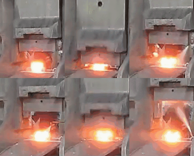
Die forging is a precision metal forming process that utilizes specialized dies and forging equipment to shape metal blanks into complex, high-strength components. This method offers superior mechanical properties, improved grain flow, and near-net-shape capabilities compared to other manufacturing processes. Die forging can be classified into several categories based on the equipment used:
Roll forging, a specialized subset of die forging, is a continuous rotary forging process that uses a pair of counter-rotating dies to plastically deform the workpiece. This method is particularly effective for producing elongated, symmetrical parts such as axles, shafts, and connecting rods. Roll forging offers several advantages:
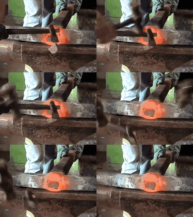
Forging is a sophisticated metal forming process that employs compressive forces to plastically deform metal, typically at elevated temperatures, to achieve desired shapes with enhanced mechanical properties. This process utilizes specialized equipment such as hydraulic presses, mechanical presses, or hammers to apply controlled pressure on heated metal billets or preforms.
The forging process can be categorized into several types, including open-die forging, closed-die forging, and precision forging, each suited for different applications and production volumes. During forging, the metal undergoes significant microstructural changes, including grain refinement and alignment, which contribute to improved strength, toughness, and fatigue resistance.
One of the key advantages of forging is its ability to eliminate internal defects such as porosity and shrinkage cavities that are often present in cast materials. The process induces a favorable grain flow pattern that follows the contours of the part, resulting in a continuous and unbroken fiber structure. This characteristic significantly enhances the mechanical properties of forged components, making them superior to cast or machined parts in terms of strength-to-weight ratio and overall performance.
Forged parts are widely used in critical applications across various industries, including aerospace, automotive, oil and gas, and heavy machinery. Components such as crankshafts, connecting rods, turbine discs, and landing gear parts for aircraft are typically forged due to their demanding operational requirements. The forging process is particularly valuable for parts subjected to high stress, impact, or fatigue loads, where the improved grain structure and mechanical properties are essential for reliability and safety.
While forging offers numerous advantages, it’s important to note that the process requires significant initial tooling investment and is most economical for medium to high production volumes. For simpler geometries or lower production quantities, alternative manufacturing methods such as casting, machining, or advanced additive manufacturing techniques may be more suitable.
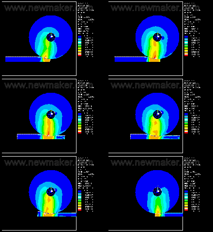
Rolling, also known as calendering in some contexts, is a fundamental metal forming process that utilizes a pair of rotating rollers to reduce the thickness of a metal workpiece while simultaneously increasing its length and modifying its microstructure. This versatile technique is widely employed in the metalworking industry due to its efficiency, precision, and ability to produce a wide range of products.
The process can be categorized into two main types based on the temperature of the metal during deformation:
Rolling is the most extensively used metal processing method in modern manufacturing, accounting for over 90% of all metals produced. Its widespread adoption is due to several factors:
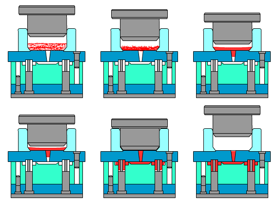
Pressure casting, also known as high-pressure die casting (HPDC), is an advanced metal forming process that combines rapid mold filling with high-pressure solidification. This technique involves injecting molten or semi-solid metal alloy into a reusable steel mold (die) at high velocities and under extreme pressure. The process is characterized by its ability to produce complex, near-net-shape components with excellent dimensional accuracy and surface finish.
In this method, liquid metal—typically aluminum, zinc, magnesium, or copper alloys—is forced into the die cavity at pressures ranging from 10 to 200 MPa (1,450 to 29,000 psi), depending on the alloy and part geometry. The high-speed injection, often exceeding 40 m/s (130 ft/s), ensures complete filling of intricate mold details before solidification begins. Once filled, the metal is held under sustained pressure throughout the solidification process, which can range from milliseconds to several seconds.
This combination of rapid filling and pressurized solidification yields several key advantages:
Pressure casting is widely used in automotive, aerospace, and consumer electronics industries for producing components such as engine blocks, transmission cases, and structural frames. Recent advancements in the field include vacuum-assisted HPDC for even higher quality castings and semi-solid metal (SSM) casting techniques for improved material properties.
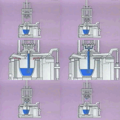
Low-pressure casting is an advanced metal forming process that involves filling a precision mold with molten metal under controlled, low-pressure conditions. This method utilizes gas pressure, typically ranging from 0.3 to 1.5 bar, to force the liquid metal upward from a pressurized furnace into the mold cavity.
Originally developed for aluminum alloy castings, low-pressure casting has since evolved to accommodate a wider range of materials, including high melting point metals such as copper alloys, cast iron, and various grades of steel. This expansion has been facilitated by advancements in furnace technology and mold design, allowing for better temperature control and improved gas pressure regulation.
Key advantages of low-pressure casting include:
The process is particularly well-suited for the production of automotive components such as wheels, cylinder heads, and engine blocks, as well as industrial pump housings and aerospace parts requiring high integrity and consistent mechanical properties.
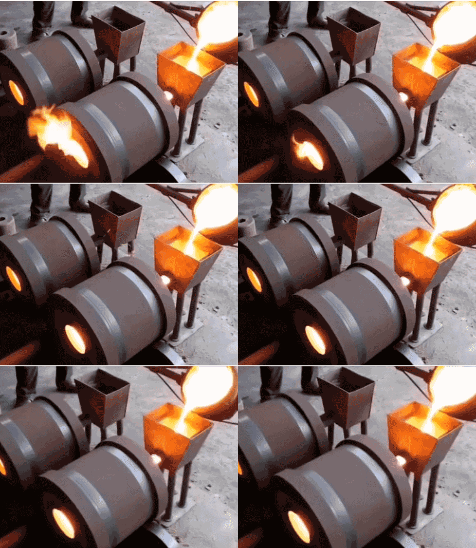
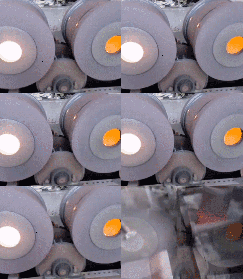
Centrifugal casting is a dynamic metal forming process where molten metal is introduced into a rapidly rotating mold. The centrifugal force generated by the rotation (typically 300-3000 RPM, depending on the mold diameter and alloy properties) drives the liquid metal outward against the mold wall, creating a uniform, dense casting with minimal porosity.
The mold selection for centrifugal casting is critical and varies based on several factors:
Mold types include:

Lost foam casting, also known as evaporative pattern casting, is an advanced metal casting process that combines precision with design flexibility. This technique utilizes an expanded polystyrene (EPS) foam pattern, similar in size and shape to the desired final casting, coated with a refractory slurry. Multiple foam patterns can be assembled with wax gates and runners to form a cluster, enhancing production efficiency.
The process begins by coating the foam pattern cluster with a ceramic slurry and allowing it to dry. This refractory coating is crucial as it maintains the cavity shape during metal pouring and improves surface finish. The coated cluster is then carefully placed in a flask and surrounded by unbonded, fine-grained silica sand, which is compacted through vibration to ensure proper support and permeability.
During casting, molten metal is poured into the mold under controlled vacuum conditions. As the metal contacts the foam pattern, it causes the foam to vaporize (or “lose”), creating a pathway for the metal to fill the cavity precisely. The ceramic coating prevents sand erosion and facilitates the escape of vaporized foam through the permeable sand.
Lost foam casting offers several significant advantages:
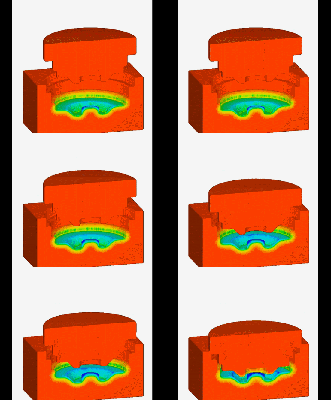
Direct extrusion casting, also known as liquid die forging, is an advanced metal forming process that combines aspects of casting and forging. This technique involves injecting molten metal or semi-solid alloy directly into an open mold cavity. Once filled, the mold is rapidly closed, inducing a complex flow pattern that shapes the outer contours of the workpiece. Subsequently, high pressure (typically 50-200 MPa) is applied, causing plastic deformation in the solidified outer shell while simultaneously subjecting the still-liquid core to intense static pressure. This dual-phase solidification under pressure results in a fine-grained microstructure with improved mechanical properties compared to conventional casting methods.
Indirect extrusion casting, a variant of this process, utilizes a sealed mold cavity. In this approach, molten metal or semi-solid alloy is injected through a specially designed punch or gate system. The sealed cavity allows for more precise control over the solidification process and pressure distribution. As with direct extrusion casting, high pressure is applied during solidification, typically ranging from 100-300 MPa depending on the alloy and part geometry. This pressure-assisted solidification promotes the formation of a homogeneous microstructure with reduced porosity and improved dimensional accuracy.
Both direct and indirect extrusion casting techniques offer several advantages for manufacturing complex, high-performance components:
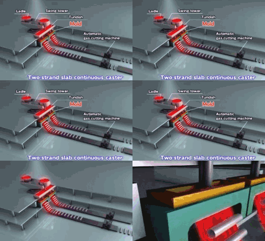
Continuous casting is an advanced, high-efficiency metal forming process where molten metal is solidified into semi-finished billets, blooms, or slabs for subsequent processing. In this method, liquid metal is continuously poured into a water-cooled copper mold (crystallizer) at one end, while the solidified product is simultaneously withdrawn from the other end at a rate that matches the inflow of molten metal.
The process begins with molten metal being poured from a ladle into a tundish, which acts as a reservoir and flow controller. From the tundish, the metal flows into the water-cooled copper mold, where initial solidification occurs. As the partially solidified strand is withdrawn, it passes through a series of water spray and roller sections that complete the solidification process and control the product’s shape.
This method offers several advantages over traditional ingot casting:
Continuous casting is widely used in the steel industry and has applications in the production of non-ferrous metals such as aluminum, copper, and zinc. Recent technological advancements include electromagnetic stirring for improved microstructure control, inline rolling for near-net-shape casting, and the use of advanced sensors and AI for real-time process optimization.
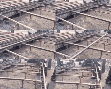
Cold drawing, also known as cold extrusion, is a metal forming process that applies tensile force to the front end of a metal workpiece, pulling it through a die with a smaller cross-sectional area than the initial billet. This operation is typically performed at room temperature or slightly elevated temperatures below the material’s recrystallization point, hence the term “cold.”
The process induces plastic deformation in the metal, resulting in:
Cold drawing is widely used in manufacturing various products, including wires, bars, tubes, and shaped profiles. The process offers several advantages:
However, the process is limited by the material’s ductility and the amount of reduction achievable in a single pass. Multiple drawing stages may be necessary for significant reductions, often with intermediate annealing treatments to restore workability.
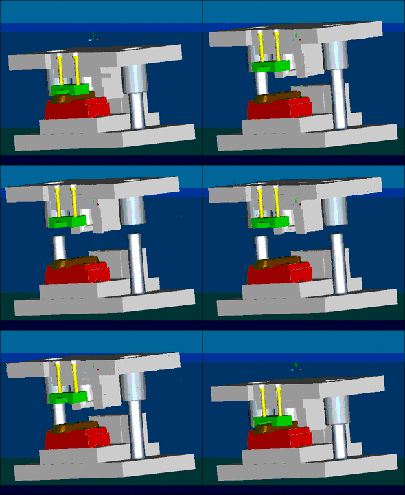
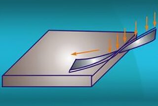
Stamping, also known as pressing, is a versatile metal forming process that transforms flat sheet metal, strips, pipes, or profiles into desired shapes and sizes through controlled deformation or separation. This process utilizes a combination of specialized tools, including punches and dies, mounted on a press machine to apply precise external forces to the workpiece.
The stamping process can be broadly categorized into two main types:
1. Plastic deformation: This involves reshaping the metal without material separation. Techniques include:
2. Separation: This involves cutting or shearing the material. Common methods include:
The effectiveness of stamping relies on careful consideration of factors such as material properties, tool design, press capacity, and process parameters. Modern stamping operations often incorporate computer-aided design (CAD) and simulation software to optimize tool geometry and process parameters, ensuring high precision and repeatability.
Stamping offers several advantages in metal fabrication, including:
As industry trends evolve, stamping technology continues to advance, with developments in high-strength materials, servo-driven presses, and in-die sensing for real-time process monitoring and quality control.
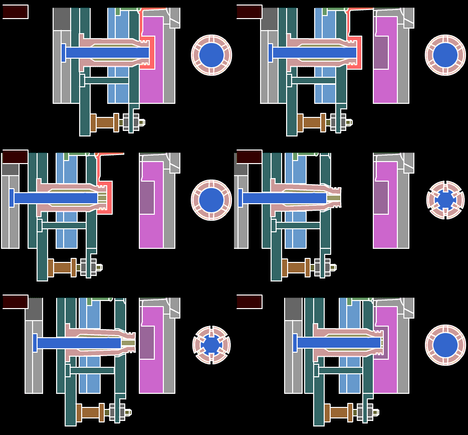
Metal Injection Molding (MIM) is an advanced powder metallurgy technique that combines the versatility of plastic injection molding with the superior mechanical properties of metals. This near-net-shape manufacturing process has evolved from the plastic injection molding industry, offering a cost-effective solution for producing complex, high-precision metal components in large volumes.
In MIM, fine metal powders (typically 20 microns or smaller) are mixed with a thermoplastic binder to create a feedstock. This feedstock is then injected into a mold cavity under high pressure, similar to conventional plastic injection molding. However, unlike its plastic counterpart, MIM produces parts with mechanical properties comparable to wrought metals.
The process involves four key stages:
Recent advancements in MIM technology have focused on maximizing the solid particle content in the feedstock, with some formulations reaching up to 65% by volume. This high metal loading, combined with precise binder removal and controlled sintering, results in final parts with densities exceeding 97% of theoretical, minimizing porosity and enhancing mechanical properties.
MIM excels in producing small, complex parts (typically 0.1 to 100 grams) with tight tolerances, making it ideal for industries such as automotive, aerospace, medical devices, and consumer electronics. The process offers significant advantages over traditional manufacturing methods, including:
As the technology continues to evolve, researchers are exploring new alloy systems, improved binder formulations, and enhanced sintering techniques to further expand the capabilities and applications of metal injection molding.

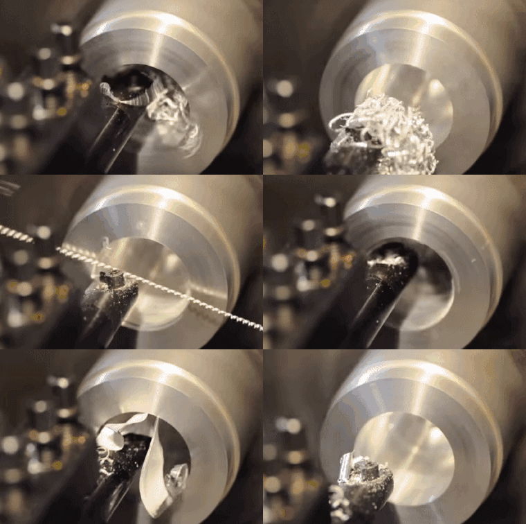
Turning is a fundamental machining process that utilizes a lathe to remove material from a rotating workpiece, creating cylindrical parts with high precision. This versatile method is essential in manufacturing various components, from simple shafts to complex contoured surfaces.
In turning operations, the workpiece is secured in a chuck or between centers and rotates at high speed. The cutting tool, typically a single-point tool, moves linearly along the axis of rotation, removing material to achieve the desired shape and dimensions. The primary cutting motion is provided by the workpiece rotation, while the feed motion is imparted by the tool’s linear movement.
Lathes are the cornerstone of many machine shops due to their versatility and efficiency. They excel in producing a wide array of rotational components, including:
Modern CNC (Computer Numerical Control) lathes have significantly expanded the capabilities of turning operations, allowing for complex geometries, tight tolerances, and high repeatability. These machines can perform multiple operations in a single setup, including:
The cutting tools used in turning operations are typically made from materials such as high-speed steel (HSS), carbide, or ceramic, depending on the workpiece material and desired surface finish. Tool geometry, including rake angle, clearance angle, and nose radius, plays a crucial role in achieving optimal cutting performance and surface quality.
Turning is particularly advantageous for its ability to produce high-precision rotational parts efficiently. It offers excellent dimensional accuracy, surface finish, and material removal rates. However, it’s important to consider factors such as cutting speed, feed rate, depth of cut, and coolant application to optimize the process for specific materials and geometries.
As manufacturing technologies advance, turning continues to evolve with innovations like multi-axis turning centers, live tooling, and integration with other machining processes, further enhancing its capabilities and efficiency in modern production environments.

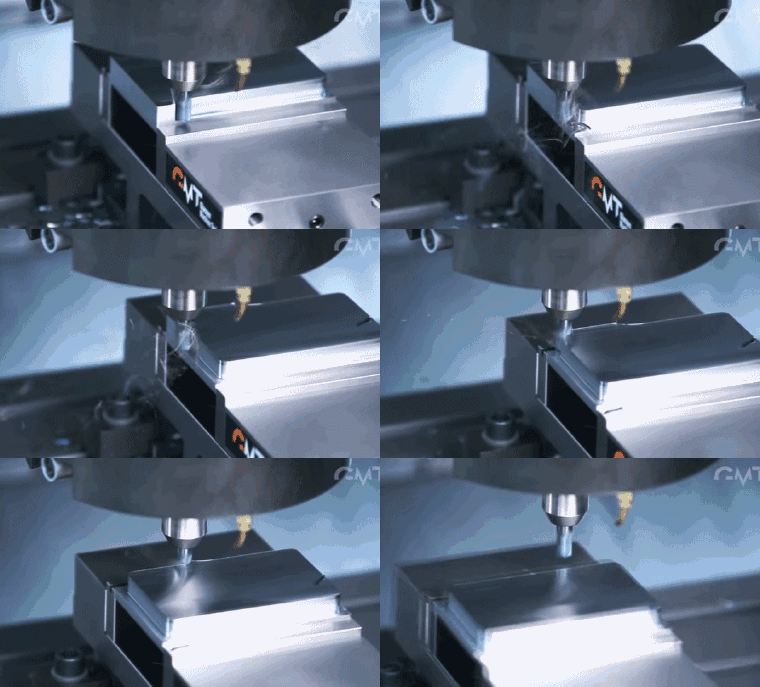
Milling is a versatile subtractive manufacturing process that involves removing material from a workpiece using rotary cutters. The process typically entails securing the workpiece (blank) to a table while a high-speed milling cutter moves across its surface, precisely removing material to create the desired shape, features, and surface finish.
Traditional milling operations excel in producing contours, grooves, slots, and flat surfaces. These operations can be categorized into face milling (for large flat surfaces) and peripheral milling (for creating deep slots and cutting gear teeth).
Computer Numerical Control (CNC) milling machines have revolutionized the milling process, enabling the fabrication of complex three-dimensional shapes and intricate features with high precision. These machines interpret programmed instructions to control cutting tool movements, speeds, and feeds, allowing for repeatable and accurate results.
Advanced milling and boring machining centers offer multi-axis capabilities, typically ranging from three-axis to five-axis configurations. These sophisticated systems excel in producing components with complex geometries, including:
When selecting a CNC milling machine, it is crucial to consider several factors to fully leverage its capabilities:
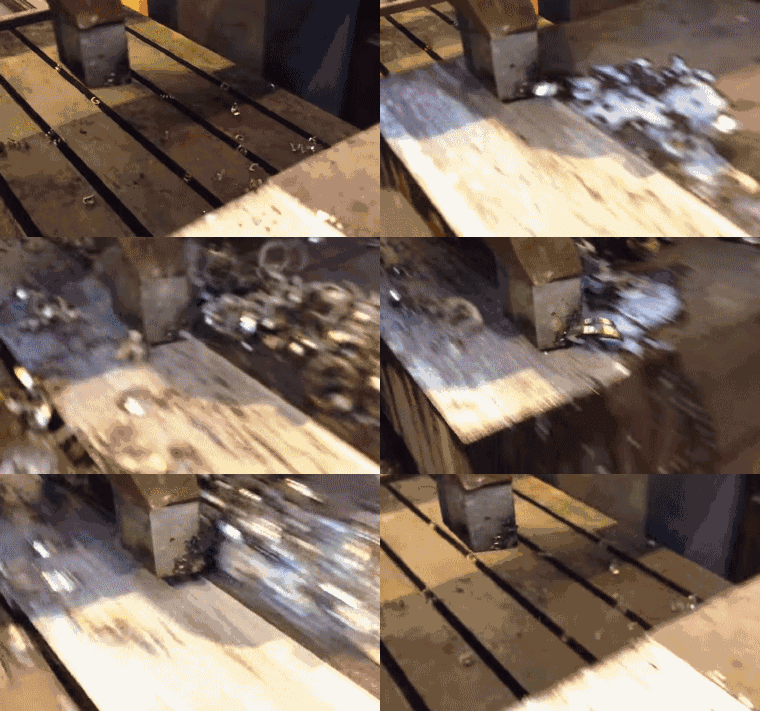
Planing is a precision machining method that utilizes a single-point cutting tool to remove material from a workpiece through a horizontal, linear reciprocating motion. This process is primarily employed for contour machining of flat surfaces, grooves, and slots on large, rigid parts such as machine beds, guide ways, and structural components. The planer tool moves across the stationary workpiece in a forward cutting stroke, followed by a non-cutting return stroke, with the workpiece being incrementally fed perpendicular to the tool motion between passes.
Modern planing machines can achieve dimensional tolerances ranging from IT9 to IT7 according to ISO standards, with surface roughness values typically between 6.3 to 1.6 μm Ra. The attainable precision depends on factors such as machine rigidity, tool geometry, cutting parameters, and workpiece material. While less common in today’s manufacturing due to the advent of more versatile CNC milling machines, planing remains valuable for specific applications, particularly in heavy industry where large, flat surfaces require machining.
Key advantages of planing include:
However, limitations such as low productivity due to the non-cutting return stroke and difficulty in machining complex contours have led to its decreased use in modern manufacturing environments. Despite these constraints, planing continues to play a niche role in certain specialized applications where its unique capabilities are advantageous.

Grinding is a precision material removal process that utilizes abrasive particles to achieve high-quality surface finishes and tight dimensional tolerances on workpieces. This versatile machining method employs bonded or coated abrasives, typically in the form of grinding wheels, belts, or discs, to remove excess material through controlled abrasion. The process is characterized by its ability to handle a wide range of materials, including metals, ceramics, and composites, making it indispensable in various manufacturing sectors.
In metalworking, grinding serves multiple purposes:
The effectiveness of grinding depends on several key parameters, including wheel composition, rotational speed, feed rate, and coolant application. Advanced CNC grinding machines offer precise control over these variables, enabling complex geometries and automated production cycles. Moreover, recent innovations in superabrasives, such as cubic boron nitride (CBN) and diamond wheels, have significantly enhanced grinding performance, particularly for hard materials and high-precision applications.

In a tank filled with metal powders, a high-power carbon dioxide laser controlled by a computer selectively scans the surface of the metal. Where the laser passes, the surface of the metal is completely fused together, while the surrounding powder remains in its original state. The process occurs within a capsule filled with an inert gas.

Selective Laser Melting
In a precisely controlled build chamber filled with fine metal powders, a high-power fiber laser (typically Yb-fiber or Nd:YAG) guided by a sophisticated computer system selectively scans the powder bed surface. The laser’s intense energy rapidly melts and fuses the metal particles in its path, creating a solid layer according to the 3D model’s cross-section. Surrounding powder remains unaffected, serving as support for subsequent layers. This layer-by-layer process occurs within an inert atmosphere (usually argon or nitrogen) to prevent oxidation and ensure optimal material properties. The build platform lowers incrementally, typically by 20-100 microns, allowing for the deposition of a new powder layer and continuation of the build process. SLM enables the production of complex geometries with internal features, optimized topologies, and functionally graded materials, revolutionizing design possibilities in aerospace, medical, and high-performance engineering applications.

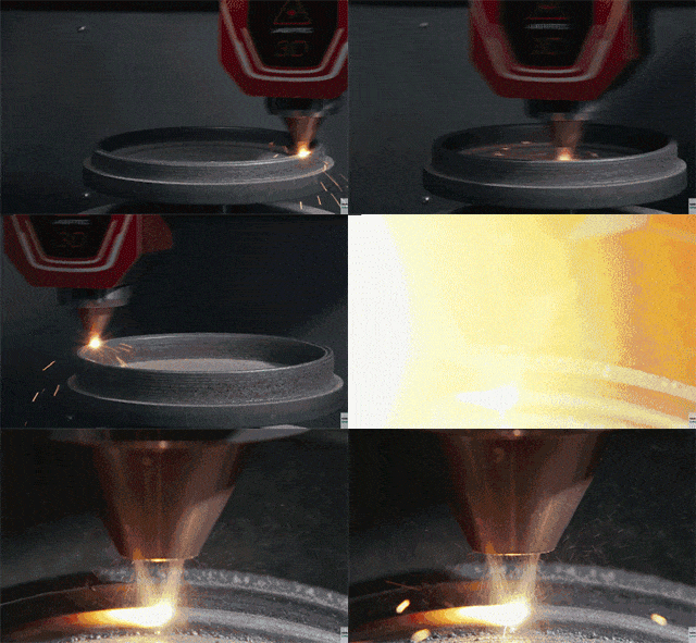
This advanced additive manufacturing process, known as Laser Metal Deposition (LMD) or Directed Energy Deposition (DED), utilizes metal powder as feedstock. Unlike traditional squeeze casting, LMD employs a sophisticated nozzle system that precisely ejects metal powder while simultaneously delivering a high-powered laser beam. The laser melts the powder particles in-flight, creating a localized melt pool on the substrate or previously deposited layers. Concurrently, an inert gas shield (typically argon or nitrogen) is provided to protect the melt pool from oxidation, ensuring high-quality deposition.
LMD offers several advantages over conventional manufacturing methods:
The versatility of LMD makes it an ideal solution for various applications, from rapid prototyping and small-batch production to repair of high-value components such as turbine blades, molds, and dies. Its ability to deposit material on existing parts also opens up possibilities for hybrid manufacturing, combining additive and subtractive processes for optimal efficiency and design freedom.
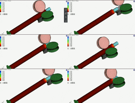
Roll forming is a highly efficient continuous manufacturing process that utilizes a series of precisely designed roller stations to progressively shape flat stainless steel sheets or coils into complex, uniform cross-sectional profiles. This method is particularly advantageous for producing long, straight parts with consistent cross-sections.
The process begins with a coil of stainless steel that is fed through a sequence of rotating tool rolls, each set mounted on its own shaft in a standalone frame. These rolls are strategically arranged in a specific order, with each subsequent station incrementally bending the metal closer to its final form. The number of stations required depends on the complexity of the desired profile and the material properties of the stainless steel being formed.
For simple shapes, such as basic channels or angles, 3-4 frames may suffice. However, more intricate profiles with multiple bends, tight radii, or special features can necessitate up to 36 or more frames to achieve the desired geometry without compromising material integrity or surface finish. The gradual forming process helps minimize residual stresses and maintain tight tolerances, making roll forming ideal for producing high-precision components for various industries, including construction, automotive, and aerospace.

Die forging is a precision metal forming process that utilizes specialized equipment to shape a preformed metal blank (billet) into complex, near-net-shape components. This process employs a set of dies—typically made from high-strength tool steel—that are designed to impart specific geometries and features onto the workpiece under high pressure and controlled temperature conditions.
The forgings produced through this process are distinguished by their exceptional dimensional accuracy, minimal machining allowance, ability to create intricate geometries, and high production efficiency. The combination of heat and pressure allows for improved grain flow within the metal, resulting in enhanced mechanical properties such as strength, toughness, and fatigue resistance.
Key advantages of die forging include:
While die forging offers numerous benefits, it’s important to consider factors such as initial tooling costs, material selection, and design complexity when evaluating its suitability for specific applications.
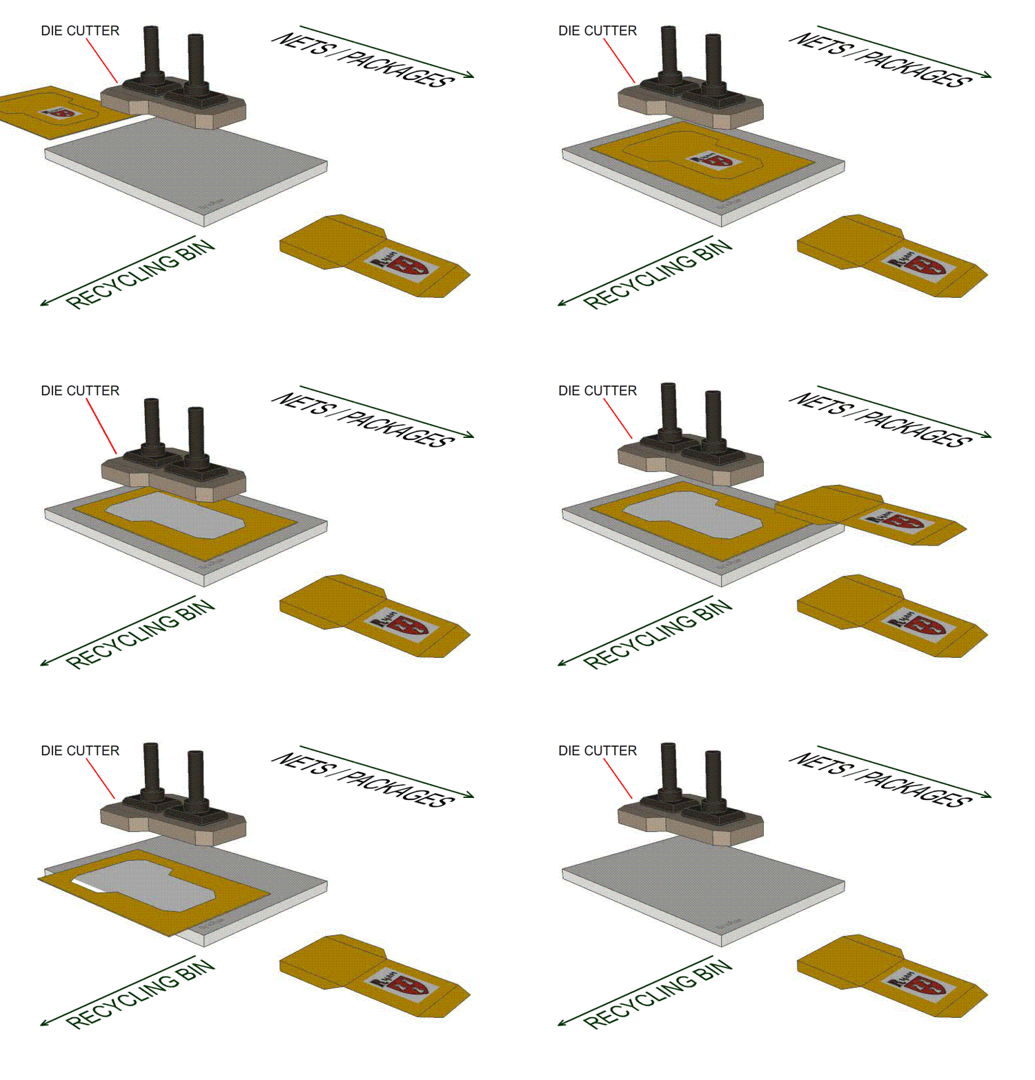
This technology falls under the category of blanking, a precision metal forming process widely used in sheet metal fabrication.
The preformed film is carefully positioned on the male die of the punch press, which utilizes a compound die to simultaneously remove excess material and preserve the intricate 3D shape of the product. This sophisticated die design incorporates multiple cutting and forming operations in a single stroke, ensuring optimal material utilization and maintaining tight tolerances. The process guarantees a precise fit with the mold cavity, critical for subsequent manufacturing steps.
The compound die typically consists of a series of strategically placed cutting edges, forming punches, and pressure pads. As the press cycles, it executes a carefully choreographed sequence of cuts and forms, resulting in a finished part that requires minimal secondary operations. This approach significantly enhances production efficiency and part consistency, particularly in high-volume manufacturing scenarios.
Material selection for both the workpiece and die components is crucial, with considerations given to factors such as material hardness, thickness, and formability. Advanced die materials, such as tool steels with specialized coatings, are often employed to extend die life and maintain cutting edge sharpness over extended production runs.

This technology refers to the precision blanking process utilizing a specialized cutting die.
The thin film panel or linear material is accurately positioned on the base plate, while the cutting die is securely fastened to the machine’s template mold. The machine then employs controlled force to drive the blade, effectively shearing the material along predefined paths.
A key distinguishing factor from conventional punching die technology is the superior edge quality it produces. The cut edges are notably smoother, with minimal burrs and reduced material deformation. Furthermore, this process allows for fine-tuned control over the cutting pressure, enabling the creation of various effects such as indentations, score lines, and partial cuts (kiss cuts) with high precision.
The versatility of mold cutting extends to its ability to produce complex geometries and intricate patterns in a single operation, significantly enhancing production efficiency. The technology is particularly well-suited for processing thin, flexible materials such as films, foils, and laminates commonly used in packaging, electronics, and automotive industries.
Another significant advantage of this technology lies in its cost-effectiveness. The molds used are relatively inexpensive to produce and maintain compared to traditional hard tooling. This aspect, combined with quick changeover times, makes the process highly adaptable to varying production requirements and small to medium batch sizes.
The mold cutting process also offers enhanced safety features, as the cutting action is fully enclosed within the machine, reducing operator exposure to sharp edges and moving parts. Additionally, the precision control and repeatability of the process contribute to consistent product quality and reduced material waste, aligning with lean manufacturing principles and sustainability goals.

