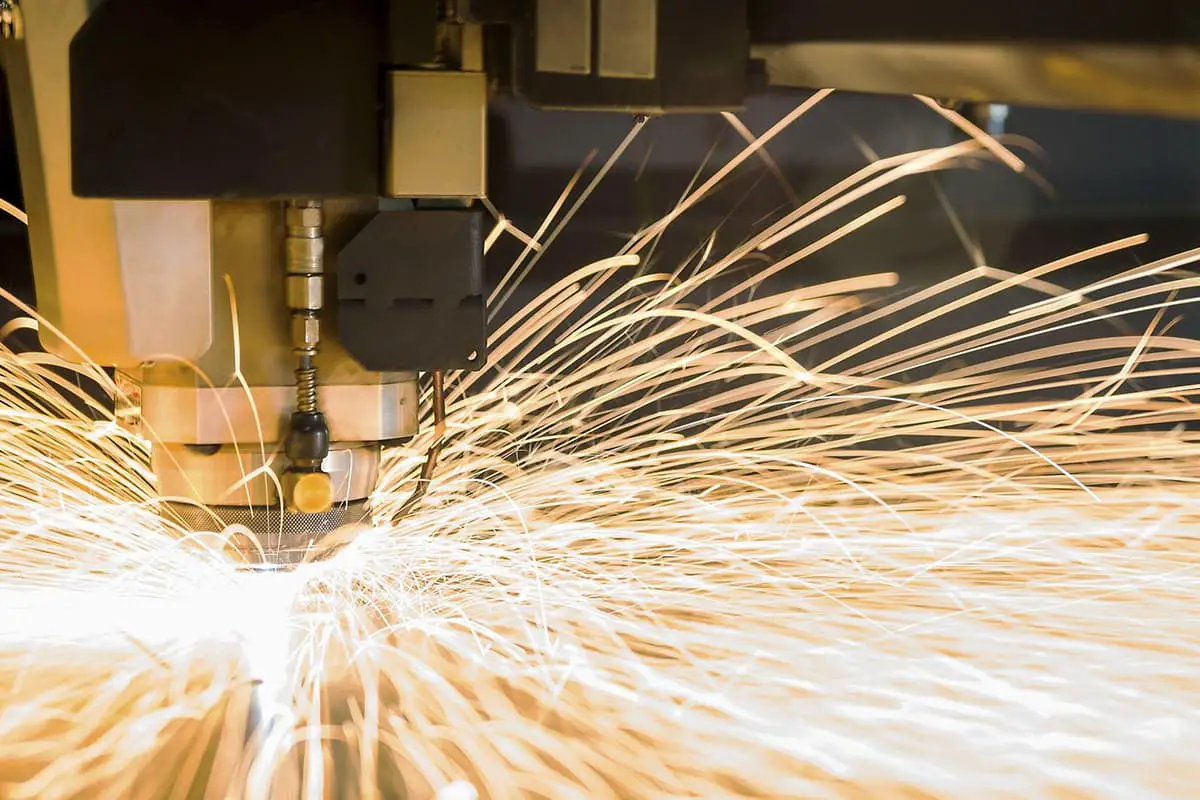
What is laser cutting machine? The laser cutting machine is a state-of-the-art plate processing equipment in the industrial sector. In the actual production process, the cutting method directly impacts both the production efficiency and the quality of the workpiece. Hence, it is crucial to discover effective cutting techniques to enhance production efficiency, improve product quality, […]
The laser cutting machine is a state-of-the-art plate processing equipment in the industrial sector.

In the actual production process, the cutting method directly impacts both the production efficiency and the quality of the workpiece. Hence, it is crucial to discover effective cutting techniques to enhance production efficiency, improve product quality, and decrease the waste rate of plates.
This post focuses on several cutting methods that have been successfully implemented in the production process, such as the use of frog leaping empty stroke feed, centralized perforation, micro connection, and the optimization of perforation points in laser cutting.
By implementing these techniques in actual production, the cutting quality and processing efficiency of the workpiece are significantly improved.
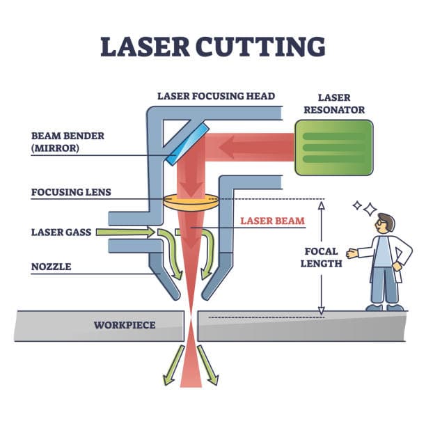
Laser cutting is a highly controlled, non-contact processing method that utilizes high energy density. A laser generator is used to emit a laser beam that is focused into a spot with a diameter of less than 0.1mm through an optical path system. This results in high power density laser beam irradiation conditions.
The heat generated from the laser beam causes the workpiece material to rapidly reach its melting point. This results in the material liquefying and forming holes, which eventually becomes a continuous slit with the help of high-pressure air flow and relative movement between the beam and workpiece.
To enhance the melting process, improve cutting speed and quality, and protect the cutting seam from oxidation, it is important to add an auxiliary gas that is suitable for the material being cut.
Laser cutting is one of several common cutting methods, including straight cutting, wire cutting, profiling cutting, flame cutting, water jet cutting, and so on. Among these methods, laser cutting is becoming increasingly popular for cutting steel plates less than 16mm due to its smooth and accurate incisions, high speed, low noise, minimal dust, and ability to cut complex shapes.

In the laser cutting process, cutting techniques play a crucial role. That’s why mastering various laser cutting techniques is essential for improving production efficiency.
We have determined that several laser cutting techniques are important through experimental exploration. By incorporating these techniques into actual production, we have seen a significant improvement in production efficiency and a reduction in material waste.
Frog leaping refers to the idle movement of the laser cutting machine.
As illustrated in Figure 1, once hole 1 has been cut, hole 2 is cut. During this process, the cutting head should move from point A to point B.
It’s important to note that the laser should be turned off during this movement. This movement from point A to point B is referred to as “idle running.”
Figure 2 displays the typical idle movement of the laser cutting machine.
The cutting head must complete three actions: rising to a safe height, translating to the top of point B, and then falling.

Fig.1 Idle stroke

Fig. 2 Cutting head idle stroke mode
The efficiency of the equipment can be improved significantly by reducing the air travel time.
By performing the three actions simultaneously, the idle time can be shortened. For example, as the cutting head moves from point A to point B, it will rise and descend at the same time, similar to a frog jumping, as illustrated in Figure 3.

Fig. 3 The trajectory of the cutting head is similar to the arc of frog leaping
By using this method, only the travel time from point A to point B is utilized, and the rising and falling time is saved.
The laser cutting machine implements a “frog leaping” idle stroke feeding technique, which effectively minimizes the idle stroke movement time and enhances the processing efficiency.
Centralized perforation, also referred to as pre-perforation, is a processing technology that is not commonly found in standard laser cutting equipment.
For instance, when laser cutting a thick plate, each cutting outline must go through two stages of perforation and cutting.
The conventional process involves the following steps: perforation → cutting of profile 1 → perforation → cutting of profile 2, as illustrated in Figure 4.
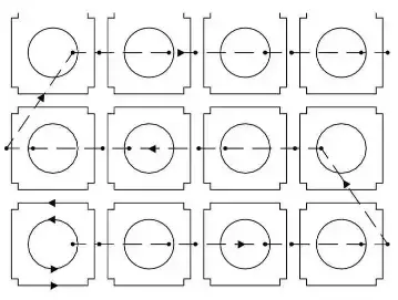
Fig. 4 Processing path of conventional laser cutting
The small dot represents the perforation point, while the arrow indicates the sequence of the cutting path.
Centralized perforation, as the name suggests, involves carrying out all the perforation processes on the entire sheet beforehand, followed by the cutting process, as depicted in Figure 5.
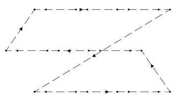
Fig. 5 Processing technology of centralized perforation
The small dot in the figure represents the perforation point, and the arrow depicts the order of the machine’s idle travel path.
The centralized perforation process involves completing the perforation of all contours, returning to the starting point, and then cutting all contours.
Compared to the conventional processing technology, the centralized perforation increases the total length of the machine’s running path, but it effectively prevents overburning.
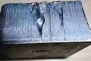
In the process of perforating thick plates, heat accumulation occurs around the perforation point. If the plate is immediately cut, overburning will occur (as shown in Figure 6).
By completing all the perforations, returning to the starting point, and then cutting, the centralized perforation process allows sufficient time for heat dissipation, thus avoiding the overburning phenomenon.
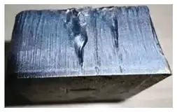
Fig. 6 Overburning of cutting surface
During laser cutting, the sheet metal is secured by a serrated support bar.
If the cut pieces are not small enough, they may not fall through the gaps of the support bar.
If they are not large enough, they cannot be properly supported by the bar and can become unbalanced, resulting in warping of the workpiece.
Additionally, if the cutting head moves too quickly, it may collide with the unbalanced workpiece, potentially causing shutdown or damage to the machine, as illustrated in Figure 7.
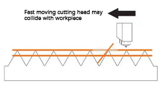
Fig. 7 Collision between the cutting head and warped workpiece
However, this type of issue can be prevented through the use of micro connection cutting technology.
The specific method is as follows:
When programming the laser cutting of a figure, the closed outline is intentionally interrupted at several locations to prevent the parts and surrounding material from separating after cutting. These interruptions are referred to as micro connections (Figure 8).
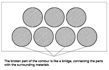
Fig. 8 Micro connection
The disconnection distance is typically between 0.2-1mm and should be chosen based on the principle that the disconnection distance is inversely proportional to the thickness of the sheet.
In the laser cutting process, when using micro connections to connect the parts with the surrounding material, the appropriate number of micro connections should be added based on the length of the outline.
It is also important to differentiate between inner and outer outlines, so that the inner outline without micro connections (scrap) can be discarded, while the outer outline with micro connections (workpiece) will be attached to the base metal, eliminating the need for sorting.
In general, the size of the cutting hole is specified as follows:
(1) For cutting carbon steel plates with a thickness of 8mm or less, the hole diameter should not be less than the thickness of the plate.
(2) For cutting carbon steel plates with a thickness of 10mm or less, the hole diameter should not be less than 1.2 times the thickness of the plate.
(3) For cutting stainless steel plates with a thickness of 4mm or less, the hole diameter should not be less than the thickness of the plate.
(4) For cutting stainless steel plates with a thickness greater than 4mm, the hole diameter should not be less than 1.2 times the thickness of the plate.
However, during laser cutting production, we often encounter workpieces with holes smaller than the thickness of the plate, which are difficult to process and result in poor cutting quality.
The main reason for this is that when the machine tool cuts a circular hole with a diameter smaller than the thickness of the plate, the default cutting mode changes from continuous cutting to pulse perforation cutting, causing the laser energy to become too concentrated in a small area. This leads to burning in the non-machining area, causing hole deformation and affecting the processing quality.
After exploration and experimentation, our company found that by using melting cutting instead of flame cutting, we can improve the cutting quality. This involves adjusting the cutting state when cutting small round holes, using high-pressure nitrogen instead of oxygen, and then switching back to oxygen cutting once the small holes have been cut.
This method results in small holes that are very regular on both sides and meet the required specifications, reducing the rejection rate and improving production efficiency.
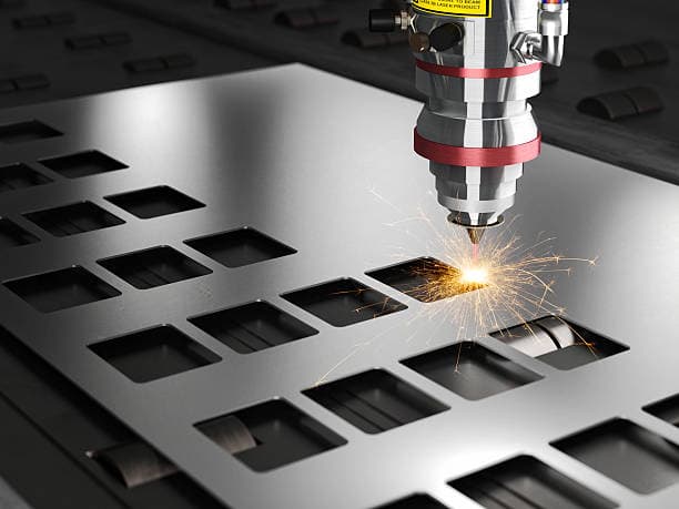
In laser cutting, the material is continuously irradiated by the laser beam, creating a pit in the center. The molten material is then quickly removed by an airflow that is coaxial with the laser beam, forming a small hole. This hole serves as the starting point for contour cutting, much like a threading hole in WEDM.
Typically, the laser beam’s line direction in the flying light path is perpendicular to the tangent direction of the machined part’s cutting contour. As a result, there is a significant change in the cutting direction from when the laser beam begins to penetrate the material to when it enters the contour cutting.
The tangent direction changes from being perpendicular to the cutting contour to coinciding with it, resulting in a rough cutting surface on the processed material when the included angle with the tangent of the contour is 0°. This occurs because the direction of the laser beam changes too rapidly.
Therefore, it’s important to consider this issue when using laser cutting. When the workpiece doesn’t have surface roughness requirements, manual processing can be omitted in the laser cutting programming, allowing the control software to generate the perforation points automatically. However, if the cutting section of the workpiece requires higher accuracy, manual adjustment of the perforation point may be necessary.
When compiling the laser cutting program, it may be necessary to manually adjust the starting position of the laser beam, or the perforation point, by moving the original perforation point generated by the laser program to a more reasonable position that meets the surface accuracy requirements of the machined part.
For example, as shown in Fig. 9, if the workpiece requires a smooth cutting surface for its arc part, the cutting start (perforation point) should be set at A and C, not B and D. On the other hand, if the workpiece only requires a rough surface for its straight edge, the cutting start should be set at B and D, not A and C.
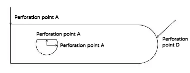
Fig. 9 Selection of piercing points in laser cutting
Similarly, as demonstrated in Figure 10, if the shape design of the workpiece requires accurate arcs, the cutting starting point (perforation point) can only be set at point D when compiling the laser cutting program.
However, if the straight-line edges only require accuracy, any point except point D can be selected when programming the laser cutting program.
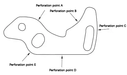
Fig. 10 Selection of piercing points in laser cutting
The operation of a laser cutting machine during the production process is complex and requires precision. It deals with a diverse range of workpieces and materials.
With the advancement of cutting technology, utilizing various cutting techniques and gaining experience in problem-solving can greatly enhance both the efficiency and output capacity of both operators and equipment.

