Punching Force Calculator & Formula (Online & Free)
Have you ever wondered how to ensure a successful metal stamping project? In this blog post, we'll dive into the critical factors that can make or break your stamping process.…
Plasma cutting is a machining method that uses the heat of a high-temperature plasma arc to make the metal at the cut of the workpiece partially melt and evaporate, and with the momentum of high-speed plasma, the molten metal is expelled to form a cut. As it relies on melting rather than oxidation reactions to […]
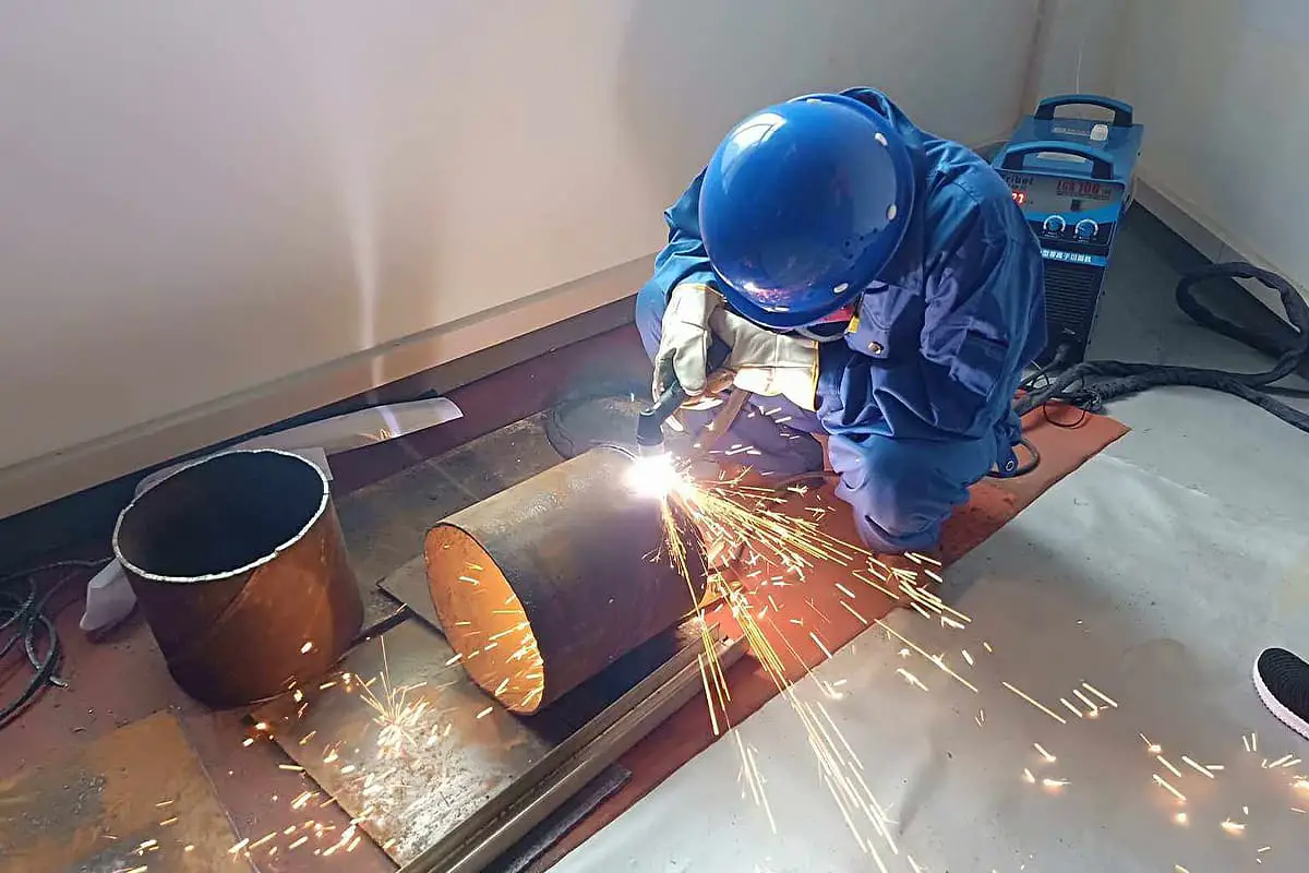
Plasma cutting is a machining method that uses the heat of a high-temperature plasma arc to make the metal at the cut of the workpiece partially melt and evaporate, and with the momentum of high-speed plasma, the molten metal is expelled to form a cut.
As it relies on melting rather than oxidation reactions to cut materials, its application range is much wider than oxy-fuel cutting. It can cut virtually all metals, non-metals, multilayer and composite materials.
The cuts are narrow with good surface quality, fast cutting speed, and can reach a thickness of 160 mm.
Moreover, due to the high temperature and high speed of the plasma arc, there is no deformation when cutting thin plates.
Particularly when cutting stainless steel, titanium alloys and non-ferrous metal materials, excellent cutting quality can be achieved.
Therefore, plasma cutting is widely used in industries such as automobiles, pressure vessels, chemical machinery, nuclear industry, general machinery, construction machinery, and steel structures.
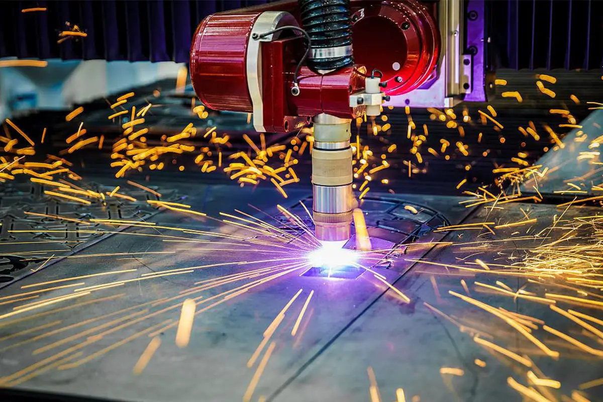
A plasma cutter ionizes mixed gases through a high-frequency electric arc, causing some gases to “decompose” or ionize into basic atomic particles, thus generating “plasma.
When the arc jumps onto the workpiece, high-pressure gas blows the plasma out of the torch nozzle at an outlet speed of 800-1000 m/s (about 3 Mach).
The temperature of the plasma arc column is extremely high, reaching 10,000°C to 30,000°C, far exceeding the melting point of all metal or non-metal materials.
This causes the workpiece being cut to melt quickly, and the molten metal is blown away by the ejected high-pressure air stream.
Therefore, smoke extraction and slag removal equipment are needed. Plasma cutting combined with different working gases can cut various metals difficult to cut with oxy-fuel cutting, especially non-ferrous metals (stainless steel, aluminum, copper, titanium, nickel) with better cutting effects.
Its main advantages are that when cutting metal materials with not too large thickness, plasma cutting is fast, especially when cutting ordinary carbon steel thin plates, the speed can reach 5-6 times that of oxy-fuel cutting with a smooth cut surface, minimal thermal deformation and virtually no heat-affected zone.
With the development of plasma cutting, the working gas used (the working gas is the conductive medium of the plasma arc, and is the heat carrier, and also expels the molten metal from the cut) has a significant effect on the cutting characteristics of the plasma arc as well as the cutting quality and speed.
Commonly used plasma arc working gases include argon, hydrogen, nitrogen, oxygen, air, steam, and certain mixed gases.
It is one of the most important characteristics to assess the quality of a cutter’s operation and reflects the minimum radius the cutter can handle. It is measured at its widest point, with most plasma cutters producing a kerf width between 0.15 and 6.0 mm.
Influencing factors include: a. Excessively wide kerfs not only waste material but also reduce cutting speed and increase energy consumption. b. The kerf width is primarily related to the nozzle aperture, typically being 10% to 40% larger than it. c.
As the cutting thickness increases, a larger nozzle aperture is often needed, which in turn widens the kerf. d. An increased kerf width can lead to greater deformation of the part being cut.
This describes the appearance of the cut surface and determines whether further processing is necessary after cutting. It is also a measure of the Ra value at two-thirds of the cut depth.
The roughness is mainly due to longitudinal vibrations caused by the cutting airflow in the direction of cutting, which result in cut ripples.
The general requirement for the surface roughness after oxyacetylene cutting is: Class 1 Ra≤30μm, Class 2 Ra≤50μm, Class 3 Ra≤100μm.
Plasma arc cutting typically produces a greater Ra value than flame cutting but less than laser cutting (less than 50μm).
This is another important parameter reflecting cutting quality and relates to the degree of further machining required after cutting. This index is often represented by verticality U or angle tolerance.
For plasma arc cutting, the U value is closely related to plate thickness and process parameters, usually U≤(1%~4%)δ (δ being the plate thickness).
This metric is crucial for hardenable or heat-treatable low-alloy steels or alloy steels, as a wide heat-affected zone can significantly alter the properties near the cut.
Air plasma arc cutting has a heat-affected zone width of about 0.3 mm, which can be narrower in underwater plasma arc cutting.
This describes the amount of oxidized slag or recrystallized material adhering to the lower edge of the cut after thermal cutting. The degree of dross is usually determined by visual inspection, often described as none, slight, moderate, or severe.
Additionally, there should be specific requirements for cut linearity, top edge melting, and notches.
The surface quality of a plasma arc cut is generally between that of oxyacetylene cutting and bandsaw cutting.
Compared to mechanical cutting, plasma arc cutting has a greater tolerance. When the plate thickness exceeds 100 mm, slower cutting speeds cause more metal to melt, often resulting in a rough cut.
The standard for a good cut is: narrow width, rectangular cross-section, smooth surface, no slag or dross, and the hardness of the cut surface should not hinder subsequent machining.
Kerf width refers to the distance at the top edge of the cut between the two faces caused by the cutting beam. In the case of melting at the top edge of the cut, it denotes the distance between the two cutting faces right below the melting layer.
The plasma arc often removes more metal from the top than the bottom of the cut, causing a slight tilt in the cut face, with the top edge typically appearing square, but sometimes slightly round.
The kerf width of plasma arc cutting is 1.5 to 2.0 times wider than oxygen acetylene cutting, and as the plate thickness increases, the kerf width also increases.
For stainless steel or aluminum with a thickness of less than 25 mm, low current plasma arc cutting can be used, which results in a higher straightness of the cut.
Especially with a cutting thickness less than 8mm, small edges can be cut, and sometimes it can be welded directly without further processing, which is difficult to achieve with high current plasma arc cutting.
This provides convenience for irregular curve blanking and non-standard hole cutting in thin plates. The flatness of the cutting surface refers to the distance between two parallel lines made in the direction of the cutting surface angle, from the highest and lowest points on the cut surface.
The surface of the plasma arc cut has a molten layer about 0.25 to 3.80 mm thick, but its chemical composition remains unchanged.
For example, when cutting an aluminum alloy containing 5% w(Mg), although there is a 0.25 mm thick molten layer, the composition remains unchanged, and no oxide appears.
If the cutting surface is welded directly, a dense weld can still be obtained. When cutting stainless steel, as the heat-affected zone quickly passes through the critical temperature of 649 ℃, chromium carbide will not precipitate along the grain boundary. Thus, plasma arc cutting of stainless steel does not affect its corrosion resistance.
Irregular notches of varying widths, depths, and shapes on the cutting surface interrupt the uniformity of the cut. The iron oxide dross that attaches to the lower edge of the cutting surface after cutting is known as hanging slag.
Taking stainless steel as an example, due to the poor fluidity of the molten stainless steel, it is difficult to blow all the molten metal from the cut during the cutting process.
Stainless steel has poor thermal conductivity, and the bottom of the cut can easily overheat, leaving behind molten metal that was not blown away.
This fuses with the bottom of the cut and solidifies upon cooling to form what is referred to as dross or hanging slag. Stainless steel is tough, and this dross is very robust, making it difficult to remove and causing significant challenges for machining.
Therefore, removing dross from plasma arc cutting of stainless steel is a critical issue.
When cutting copper, aluminum, and their alloys, due to their good thermal conductivity, the bottom of the cut is less likely to re-melt with the molten metal.
Although this dross “hangs” under the cut, it is easy to remove. When using plasma arc cutting, the specific measures to remove dross are as follows:
(1) Ensure concentricity between the tungsten electrode and the nozzle
Poor alignment of the tungsten electrode and the nozzle can disrupt the symmetry of the gas and arc, preventing the plasma arc from being well compressed or causing arc deflection.
This reduces cutting capability, results in asymmetric cuts, increases the occurrence of melt lumps, and in severe cases causes double arcs that disrupt the cutting process.
(2) Ensure that the plasma arc has sufficient power
With increased plasma arc power, the energy of the plasma arc increases and the arc column lengthens, raising the temperature and fluidity of the melting metal during the cutting process.
Under the effect of high-speed airflow, the melted metal can be easily blown away.
Increasing arc column power can improve cutting speed and the stability of the cutting process, enabling the use of larger airflow to increase the blowing force, which is highly beneficial for eliminating melt lumps in the cut.
(3) Choose the right gas flow and cutting speed
Insufficient gas flow can easily lead to the formation of melt lumps. With all other conditions unchanged, as the gas flow increases, the cut quality improves and a cut free of melt lumps can be achieved.
However, excessive gas flow will shorten the plasma arc, reducing its melting capability on the lower part of the workpiece, increasing the lag behind the cut, causing the cut to take on a V shape, and consequently facilitating the formation of melt lumps.
The occurrence of double arcs in transferred plasma arcs is related to specific process conditions. In plasma arc cutting, the presence of double arcs inevitably leads to rapid nozzle wear.
Minor wear changes the geometric shape of the nozzle hole, destabilizing the arc and impacting cut quality; severe wear can cause nozzle leakage, forcing the cutting process to stop.
Therefore, as with plasma arc welding, it’s crucial to consider the factors affecting the formation of double arcs to prevent their occurrence.
In production, plasma arc cutting can now be used to cut stainless steel with a thickness of 100 to 200 mm. To ensure the quality of cutting thick plates, the following technical characteristics should be taken into account:
(1) As the cutting thickness increases, the amount of metal to be melted also increases, thus a larger plasma arc power is required. When cutting plates thicker than 80 mm, the plasma arc power is between 50 to 100 kW.
To reduce nozzle and tungsten electrode wear, it is advisable to increase the cutting voltage of the plasma arc at the same power.
Therefore, the no-load voltage of the cutting power supply should be above 220 V.
(2) The plasma arc should be slim and rigid, with the arc column maintaining a high temperature over a long distance.
That is, the axial temperature gradient should be small, and the temperature distribution on the arc column should be uniform. This way, the bottom of the cut can get enough heat to ensure penetration.
The effect is even better if a mixture of nitrogen and hydrogen with a large heat enthalpy and high thermal conductivity is used.
(3) During arc transfer, due to large current fluctuations, arc interruption or nozzle burnout often occurs, so it is necessary for the equipment to use a method of increasing the current gradually or transferring the arc in stages.
Generally, a current limiting resistor (about 0.4 Ω) can be inserted in the cutting circuit to reduce the current value during arc transfer, and then the resistor is shorted out.
(4) Preheating is required when cutting begins, and the preheating time is determined by the properties and thickness of the material being cut.
For stainless steel, when the workpiece thickness is 200 mm, preheating for 8 to 20 seconds is necessary; when the workpiece thickness is 50 mm, 2.5 to 3.5 seconds of preheating is required.
After the cutting of a thick workpiece begins, you should wait until it has been cut through along the thickness direction before moving the cutting torch to achieve continuous cutting, otherwise the workpiece will not be completely cut.
Arc should be cut off only after the work is completely separated.
Quality Control Measures:
To avoid welding defects, a strict cleaning procedure should be followed before welding; to control the misalignment on both sides of the weld, welding fixtures have been used and positioned; to avoid oxidation of the inner wall of the welded shell, internal argon filling protection has been adopted.
(1) Martensitic precipitation-hardened stainless steel displays excellent weldability and can be welded in any state – solution-treated, aged, or over-aged – without requiring pre-heating or post-welding slow cooling.
However, if equivalent strength in the weld joint is required, the same chemical composition as the base material must be used for the filler material, and post-weld solution treatment and aging heat treatment must be performed.
(2) To mitigate softening and segregation in the joint, when welding martensitic precipitation-hardened stainless steel using fusion welding, the input of line energy must be strictly limited.
Electron beam welding, laser welding, and pulsed tungsten inert gas welding are preferential choices. When using resistance welding, rigid specifications should be adhered to.

As the founder of MachineMFG, I have dedicated over a decade of my career to the metalworking industry. My extensive experience has allowed me to become an expert in the fields of sheet metal fabrication, machining, mechanical engineering, and machine tools for metals. I am constantly thinking, reading, and writing about these subjects, constantly striving to stay at the forefront of my field. Let my knowledge and expertise be an asset to your business.