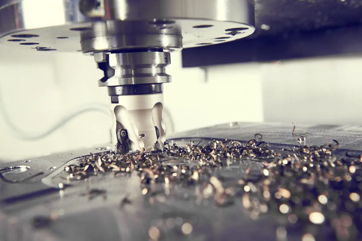
Ever wondered how intricate metal parts are crafted with precision? This article unveils the magic of milling machines, exploring their various types and key components. Dive in to understand how these machines transform raw materials into finely detailed products, and discover the essential tools that make it all possible.
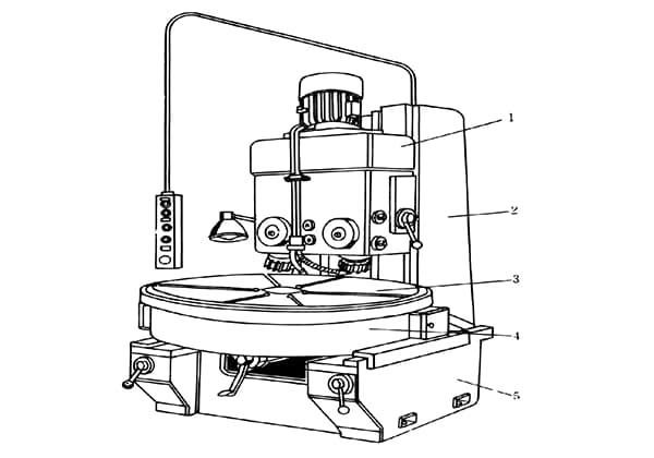
The milling machine is a versatile and widely used machine tool in metalworking and manufacturing. Its primary motion is characterized by the high-speed rotational movement of the multi-edged milling cutter, while the feed motion typically involves the precise, controlled movement of the workpiece, which is securely mounted on the machine’s worktable.
Milling machines come in various configurations, each designed for specific applications and workpiece requirements. Some of the most common types include:
Each type of milling machine offers unique capabilities, and the selection depends on factors such as workpiece size, material, required accuracy, and production volume. Modern CNC (Computer Numerical Control) technology has further enhanced the versatility and precision of milling operations, enabling complex 3D machining and seamless integration with CAD/CAM systems for advanced manufacturing processes.
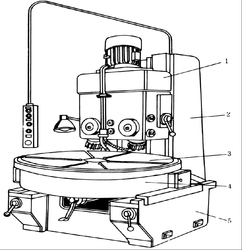
(1) Bed
The bed is the main body of the machine tool, with most components installed on it.
The spindle, spindle speed changing mechanism, and other parts are installed inside the bed.
The front wall of the bed has vertical dovetail guide rails for the up and down movement of the table, while the top of the bed has horizontal dovetail guide rails for the forward and backward movement of the crossbeam.
At the back of the bed, there is a main motor that drives the spindle through a speed changing mechanism installed inside the bed.
The spindle speed is changed using a handle and a dial scale, both of which are located on the upper left side of the bed. It is necessary to stop when changing speeds.
An electrical cabinet is located at the lower left side of the bed.

(2) Crossbeam
The crossbeam can be adjusted for length by moving it forward or backward with the help of gears and racks, and can be clamped using two sets of eccentric bolts.
A bracket is installed on the crossbeam to support the overhanging end of the cutter bar, which enhances the rigidity of the cutter bar.
(3) Table
It is the support for the worktable, with the longitudinal worktable, transverse worktable and rotary table of the milling machine mounted on it.
The feed motor and feed speed changing mechanism are independent components installed on the front left side of the table, which control the movement of the table, longitudinal worktable and transverse worktable.
The change of the feed rate is controlled by a mushroom-shaped handle, which allows for speed changes while driving.
The table can move along the vertical dovetail guide rails of the bed. Below the table is a vertical lead screw, which not only raises and lowers the table but also supports it.
The manipulation of the transverse worktable and the lifting table is controlled by handles on the left side of the lifting table.
There are two linked handles that have five positions: up, down, forward, backward and stop. The five positions are interlocked.
(4) Longitudinal worktable
It is used to install workpieces or fixtures and moves longitudinally with the workpiece during feed motion.
There are three T-slots on top of the longitudinal worktable for installing clamp bolts (T-bolts). One of these three T-slots has higher accuracy than the other two. There is also a small T-slot on the front side of the worktable for installing travel limit blocks.
The width of the longitudinal worktable is the main specification that indicates the size of the milling machine.
(5) Transverse worktable
The transverse worktable is located below the longitudinal worktable and is used to drive the longitudinal worktable to move back and forth.
With the longitudinal worktable, transverse worktable, and lifting table, the workpiece can be moved in three mutually perpendicular coordinate directions to meet machining requirements.
There is a rotary table between the longitudinal worktable and transverse worktable of the universal milling machine. Its sole purpose is to allow the longitudinal worktable to rotate within a positive or negative angle not exceeding 45 degrees in the horizontal plane, in order to mill helical grooves.
The presence or absence of a rotary table is the only distinguishing feature between universal horizontal milling machines and ordinary horizontal milling machines.
(6) Spindle
The spindle is used to install milling cutters either directly or through a cutter arbor, and drives the milling cutter to rotate. The spindle is a hollow shaft with a 7:24 tapered hole at the front end for installing milling cutters or cutter arbors.
A long bolt passes through the spindle through-hole from the back to fasten the milling cutters or cutter arbors in place.
The base supports the entire weight of the milling machine and holds the cutting fluid. It is the foundation of the entire milling machine and is designed to ensure that the machine is stable and rigid during operation.
In addition, there are also auxiliary devices such as the crane and cutter arbor.
X6132 universal horizontal lifting table milling machine.
(1) Milling machine model and specifications.

(2) Main technical parameters:
The working surface area of the table is 320mm x 1250mm, and the maximum travel of the table (manual) is 700mm longitudinally, 255mm transversely, and 320mm vertically. The maximum travel of the table (automatic) is 680mm longitudinally, 240mm transversely, and 300mm vertically.
The maximum rotation angle of the table is ±45°, and the distance from the spindle axis to the worktable surface is 30mm to 350mm. The spindle speed has 18 levels ranging from 30rpm to 1500rpm.
Vertical lifting table milling machine.
The vertical milling machine is similar to the horizontal milling machine in many ways. However, it differs in that it has no top guide rail or crossbeam on the bed.
Instead, the front upper part of the machine has a vertical milling head, which is used to install the spindle and milling cutter.
Usually, a rotary table is placed between the bed and the vertical milling head in a vertical milling machine, which allows the spindle to tilt at a certain angle for milling inclined surfaces. The vertical milling machine can also be used for boring holes.
b) Tilting worktable

c) Rotary worktable.

d) Plain vise

e) Dividing head.

f) Vertical milling head.

g) Insert Milling Tool


Also known as a machine vise, these pliers are commonly used for holding small to medium-sized workpieces of rectangular or cylindrical shape. Pliers that feature a rotating dial are called rotary flat-nose pliers, which can be used to adjust angles.
This method is commonly used for installing small, regularly-shaped workpieces.
This tool is used for clamping workpieces that require machining of curved surfaces. It is particularly useful for milling relatively uniform inner and outer circular arc surfaces.

To expand the processing range of horizontal milling machines. Installing a universal milling head on a horizontal milling machine not only allows for various vertical milling operations, but also enables the milling cutter axis to be adjusted to any angle based on the milling needs.
However, due to the complicated installation of the universal milling head and the significant reduction in workspace after installation, its utilization is limited.


The application of a dividing head:
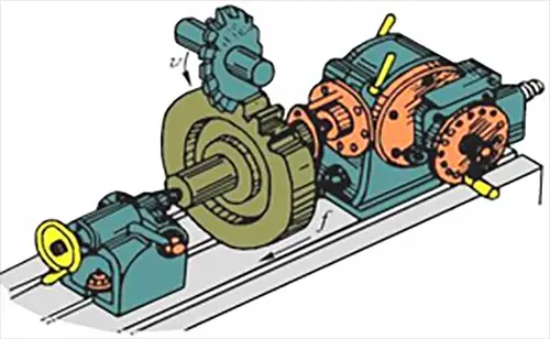
As one of the important accessories, the dividing head is commonly used for installing workpieces to mill inclined surfaces, conduct indexing operations, and by using various indexing methods (such as simple indexing, compound indexing, and differential indexing) for various indexing tasks.
Additionally, the dividing head can be utilized to install the workpiece at the required angle to facilitate cutting processing (such as milling inclined surfaces). When milling helical grooves, the dividing head can be connected to the milling machine’s longitudinal table screw with an “exchange gear” to provide the workpiece on the dividing head with spiral motion while the table moves.


Milling cutters are sophisticated multi-tooth cutting tools typically manufactured by specialized facilities due to their complex geometry and precision requirements. These tools are characterized by their high productivity, which stems from two key factors: the simultaneous engagement of multiple cutting edges and the capability to operate at elevated cutting speeds.
The design and performance of milling cutters can be optimized for specific applications, materials, and machining conditions. This versatility has led to a wide array of milling cutter types, each tailored to meet particular manufacturing needs. These cutters can be classified based on several criteria, including:
While each classification system offers valuable insights into cutter selection and performance, this discussion will focus primarily on categorization by intended application, as it provides a practical framework for understanding the diverse range of milling operations in modern manufacturing.
Key applications-based categories include:

Classification of Milling Cutters by Usage:
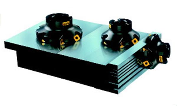
Face milling cutter
Cylindrical milling cutter
The cylindrical milling cutter is generally made of high-speed steel as a whole. The spiral cutting edge is distributed on the surface of the cylinder without secondary cutting edge. The spiral teeth gradually cut into and leave the workpiece during the cutting process, so the cutting process is relatively stable.
It is mainly used for machining narrow and long surfaces with a width less than the length of the milling cutter on horizontal milling machines.

Disc milling cutter
The disc milling cutter includes:
Slot milling cutter. It only has teeth on the surface of the cylinder and can only be used for machining shallow grooves.

Keyway milling cutter
A. It is a special cutting tool for milling keyways, with only two flutes.
B. Both the circumferential cutting edge and the end cutting edge can serve as the main cutting edge.
C. When in use, the cutter enters the workpiece first through axial feed, then mills out the keyway along the direction of the keyway.
D. Only the end cutting edge needs to be ground during regrinding.

End mill

The difference between Twist Drills, Face Milling Cutters, and Keyway Milling Cutters:


Saw blade milling cutter
Saw blade milling cutters are mainly used to cut or mill narrow grooves to a certain depth.

Angle milling cutter
Single and double angle milling cutters are used for milling grooves and bevels on workpieces.

Form milling cutter
Form milling cutters are used for machining contoured surfaces, and the shape of the cutter teeth is designed to match the contour shape of the workpiece surface being machined.

Classification of milling cutters by the shape of their tooth back:
1. Pointed tooth milling cutter
The back of the pointed tooth milling cutter is mostly linear and is milled by an angle milling cutter. This type of milling cutter is always of pointed design. It can be easily manufactured and sharpened, and can be reground along the rear cutting surface after it becomes dull. This type of milling cutter has a sharp blade edge.

2. Shaped-tooth milling cutter.
The back of a shaped-tooth milling cutter is a special curve, usually an Archimedean spiral. The tooth back is machined by the shaving method. After the tooth becomes dull, it can be reground along the front cutting surface.
The shape of the milling cutter teeth remains unchanged after regrinding. This type of milling cutter is commonly used for machining complex cutting edge shapes of form milling cutters.

Shank milling cutter:
1) End mill cutter

The teeth of the milling cutter are distributed on the end face and cylindrical surface of the cutter. It is often used to machine flat surfaces on a vertical milling machine and can also be used to machine flat surfaces on a horizontal milling machine.
2) Face mill cutter

It is suitable for milling contour surfaces, end faces, inclined planes, grooves, and step surfaces, etc.
3) Keyway milling cutter and T-slot milling cutter

It is specifically used for machining keyways and T-slots.
4) Dovetail milling cutter

It is specifically used for milling dovetail grooves.
Milling cutter with holes:

Milling is a highly versatile and productive machining method that offers exceptional precision and surface quality. Typically, milling operations can achieve dimensional tolerances ranging from IT9 to IT8 according to the International Tolerance grade system, with surface roughness values (Ra) between 6.3 and 1.6μm. These capabilities make milling suitable for a wide array of high-precision manufacturing applications.
The scope of milling encompasses a diverse range of processing capabilities, including:
Furthermore, modern milling machines offer enhanced versatility through their ability to accommodate additional tooling. By installing hole-making tools such as drills, reamers, and boring bars, these machines can efficiently perform various hole-processing operations on workpieces. This multi-functionality significantly reduces the need for multiple machine setups, thereby improving overall manufacturing efficiency and precision.
Advanced CNC (Computer Numerical Control) milling centers can further expand these capabilities, offering 5-axis machining for complex geometries and automated tool changing systems for seamless processing of diverse features. These technological advancements continue to push the boundaries of what’s achievable in milling operations, making it an indispensable process in modern manufacturing.


Definition:
Conventional milling, also known as up milling, occurs when the direction of rotation of the milling cutter opposes the feed direction of the workpiece. In this process, the cutting teeth move upward against the workpiece, lifting it slightly. Conversely, climb milling, or down milling, is characterized by the milling cutter rotating in the same direction as the workpiece feed. Here, the cutting teeth move downward into the workpiece, pushing it against the machine table.

Characteristics:
1. When conventional milling, the cutting thickness gradually increases from zero.
Due to the influence of the blunt edge radius, the front angle is negative at the beginning of cutting. The teeth are squeezed and skid on the workpiece surface, resulting in severe surface hardening and increased tooth wear.
On the other hand, when climb milling, the cutting thickness starts from maximum. The tool wear is less and the durability is high.
2. When climb milling, the cutting force in the feed direction is the same as that of the workpiece.
Due to the clearance between the screw and nut of the worktable, when the feed force gradually increases, the cutting force will pull the worktable and cause creep, resulting in uneven feed.
In severe cases, it can cause the milling cutter to break.
However, when conventional milling, due to the action of the feed force, the transmission surface between the screw and nut is always in close contact, so the milling process is relatively stable.
3. When conventional milling, the vertical cutting force is opposite to the clamping force and the weight of the workpiece, which tends to lift the workpiece off the worktable, exacerbating vibration and affecting the clamping and surface roughness of the workpiece.
On the other hand, when climb milling, the vertical cutting force is downward, resulting in reliable tightening.
Characteristics of climb milling:
Characteristics of conventional milling:

Symmetrical milling occurs when the axis of the milling cutter is positioned centrally over the machined surface. This configuration results in a balanced cutting force distribution and typically yields a larger average chip thickness. Symmetrical milling is predominantly employed for workpieces with broad machining surfaces and when processing hardened steels. The balanced force distribution contributes to improved surface finish and reduced tool wear, making it particularly suitable for high-precision applications and materials with challenging machinability characteristics.
Asymmetrical milling is characterized by the milling cutter axis being offset from the center of the machined surface. This approach can be further categorized into two distinct methods based on the relative position of the cutter axis:
a) Conventional asymmetrical milling: The cutter rotation opposes the feed direction, resulting in chips that start thin and progressively thicken. This method often provides better chip evacuation but may lead to increased cutting forces and potential workpiece lifting.
b) Climb asymmetrical milling: The cutter rotation aligns with the feed direction, producing chips that start thick and gradually thin out. This technique generally offers improved surface finish, reduced cutting forces, and enhanced tool life, but requires more rigid machine setups to prevent chatter.
The choice between conventional and climb asymmetrical milling depends on factors such as machine rigidity, workpiece material, surface finish requirements, and tool characteristics. Each method presents unique advantages and challenges, necessitating careful consideration in process planning to optimize machining outcomes.

