Why do some steel products fail unexpectedly despite high-quality manufacturing processes? The answer lies in non-metallic inclusions. These tiny impurities, formed during the steelmaking process, can significantly impact steel’s durability, toughness, and resistance to corrosion. Understanding their types and effects is crucial for improving steel quality. In this article, we’ll explore how these inclusions form, their classifications, and their profound impact on the performance of steel in various applications. Learn how to mitigate these hidden threats and ensure your steel products achieve optimal performance.
1. Endogenous inclusion
During the smelting process of steel, a deoxidation reaction occurs that results in the production of oxides and other products. If these products do not rise to the surface before the molten steel solidifies, they will remain trapped within the steel. The following reactions take place:
The presence of impurities such as oxygen, sulfur, and nitrogen in the molten steel leads to their precipitation in the solid solution during cooling and solidification, ultimately becoming trapped in the ingot. The distribution of these inclusions, known as endogenous inclusions, is typically uniform and characterized by small particles.
While proper operation and the implementation of appropriate process measures can reduce the number of inclusions and alter their composition, size, and distribution, their presence is generally unavoidable.
2. Foreign inclusions
The slag floating on the surface of molten steel during the smelting and pouring process, as well as refractory materials or other debris that may peel off from the inner walls of the steel-making furnace, tapping trough, and ladle, are not always removed before the molten steel solidifies, resulting in their presence within the steel.
These inclusions are formed as a result of contact between the metal and external substances during the smelting process.
Typically, these inclusions have an irregular shape, are large in size, and have an uneven appearance, earning them the nickname “coarse inclusions.”
However, these inclusions can be prevented through proper operation techniques.
Class A (Sulfide): Single gray inclusions with high ductility and a wide range of morphological ratios, generally with rounded ends.
Class B (Alumina): Most particles are not deformed, angular, with a small morphological ratio (generally less than 3), and are black or blue. There must be at least three particles in a row along the rolling direction.
Class C (Silicate): Single black or dark gray inclusions with high ductility and a wide range of morphological ratios (generally greater than or equal to 3), generally with an acute angle at the end.
Class D (Spherical Oxide): Undeformed, angular, or circular particles with small morphological ratios (generally less than 3), black or bluish, and irregularly distributed.
Class Ds (Single Particle Spherical): Round or nearly round single particle inclusions with a diameter of 13 μm or greater.
Table 1 rating limits (minimum)
| Rating chart level i | Inclusion category | ||||
| A. Total length (um) | B total length (um) | C Total length (um) | D quantity | S diameter (um) | |
| 0.5 | 37 | 17 | 81 | 1 | 3 |
| 1 | 127 | 777 | 6 | 41 | 9 |
| 1.5 | 261 | 84 | 769 | 2 | 7 |
| 2 | 436 | 43 | 201 | 63 | 8 |
| 2.5 | 649 | 555 | 102 | 55 | 3 |
| 3 | 898(<1181)822(<1147) | 46(<1029)3 | 6(<49)7 | 6(<107) | |
| Note: the total length of the above class A, B and C inclusions is calculated according to the formula given in Appendix D, and the nearest integer is taken. | |||||
Table 2 inclusion width
| Category | Fine system | Coarse system | ||
| Minimum width(um) | Maximum width (um) | Minimum width(um) | Maximum width(um) | |
| A | 2 | 4 | >4 | 12 |
| B | 2 | 9 | >9 | 15 |
| 2 | 5 | >5 | 12 | |
| D | 3 | 8 | >8 | 13 |
| Note: the maximum size of class D inclusions is defined as the diameter. | ||||
The presence of inclusions with a size smaller than 10μm promotes nucleation of the structure, and the grain growth occurs during welding.
(1) The addition of alloy elements such as Nb, V, Ti, and others can result in the precipitation of C and N compounds (a type of micro inclusions) during continuous casting and heating.
(2) Calcium sulfides, silicates, and fine ferrous oxide can refine the crystal nuclei, which is beneficial to the toughness, plasticity, and strength of the steel plate.
However, when the size of non-metallic inclusions exceeds 50μm, the plasticity, toughness, and fatigue life of the steel are reduced, and the cold and hot working properties, as well as some physical properties, are deteriorated.
In general, the size of inclusions in our molten steel exceeds 50μm, reducing the toughness, plasticity, and strength of the steel plate.
In addition to these properties, the inclusions also have a negative impact on acid resistance, fatigue performance, surface finish, and welding performance.
1. It is easy to crack during forging, cold working, quenching, heating and welding.
2. The surface quality after rolling and the surface roughness of the parts after grinding are reduced.
When the inclusion particles are relatively large, exceeding 10 μm in size, especially when the inclusion content is low, the yield strength and tensile strength of the steel are significantly reduced.
However, if the inclusion particles are small and measure less than 10 μm, the yield strength and tensile strength of the steel are improved.
As the amount of small particles in the steel increases, the yield strength and tensile strength also increase, but there is a slight decrease in elongation.
It is widely accepted that inclusions are the primary cause of fatigue failure in steel.
Brittle and spherical inclusions with weak binding forces and large sizes have a significant impact on fatigue performance, with higher strength leading to greater hazards, as illustrated in Figure 1.
For high-strength steel, if the component’s surface is well-processed, crack initiation and inclusion become the dominant mode of fatigue cracking.
Small inclusions may have little impact on crack nucleation but play a beneficial role in fatigue crack propagation.
Figure 2 is a schematic representation of void formation and growth around small inclusions.
It is thought that dimples are associated with inclusions smaller than 0.5mm.

Fig. 1 inclusion size and fatigue life under the same stress level

Fig. 2 Schematic diagram of formation of micro voids between non adjacent inclusions
Failure examples:
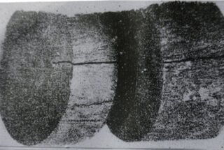
The elastic shaft of an equipment motor fails after a period of use. Figure 3 displays the fracture’s macroscopic appearance.
From the direction of the macroscopic fatigue lines on the fracture surface and the radial lines, it can be seen that the crack originates from the surface of the elastic shaft and corresponds to a longitudinal line on the shaft surface.
However, the original fracture surface’s morphological characteristics are not clear due to severe wear on the fracture surface at the crack’s initiation point.
As shown in Figure 4, a macroscopic and microscopic examination of an elastic shaft that has not failed reveals the presence of various degrees of longitudinal cracks on the shaft surface and non-metallic inclusions in the area where the cracks occur.
The results of the energy spectrum analysis indicate that the non-metallic inclusions in the cracks are aluminum oxide. The spherical oxide inclusions and single particle spherical inclusions of the motor’s elastic shaft are rated 2.0.
The primary cause of the premature failure of the elastic shaft is fatigue fracture resulting from the inclusion acting as a core fatigue source under the influence of alternating stress.
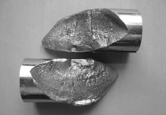
Fig. 3 macroscopic appearance of fracture of elastic shaft of fractured motor

Fig. 4 SEM analysis of inclusions in elastic shaft
The presence of non-metallic inclusions in steel can significantly decrease its resistance to corrosion.
The differences in chemical composition between the non-metallic inclusions and the steel base make it easy for a microcell to form between them. This can result in electrochemical corrosion in the presence of an environmental corrosive medium, leading to the formation of corrosion pits and cracks. In severe cases, this can result in fracture failure.
For example, a heating water pipe made of Q235B carbon structural steel leaked prematurely. Fig. 5(a) shows the macroscopic appearance of the leaking water pipe, with evidence of corrosion near the leakage point. Fig. 5(b) shows that, after removing oxidation and corrosion products, there are clear grooves in the welds at the leakage point.
A comprehensive analysis of metallography, inclusions, energy spectra, and simulated accelerated corrosion tests of both the leaked water pipe and the original water pipe revealed that the presence of oxide inclusions or composite oxide inclusions penetrating the inner surface at the weld joint were the main cause of local corrosion, the formation of corrosion grooves, and the premature leakage of the water pipe.
The corrosive media present in the pipe, such as O2, S, and Cl, caused the non-metallic inclusions to form a corrosion cell with adjacent iron, leading to electrochemical corrosion and ultimately causing the water pipe to leak.

Fig. 5 macroscopic appearance of leaking water pipe
The infiltration of hydrogen into a material or the generation of hydrogen through electrochemical interaction between the medium and the material’s surface can continue to diffuse under certain conditions and easily aggregate and combine into hydrogen molecules at traps such as inclusions.
When the pressure of hydrogen molecules at these traps exceeds the material’s strength limit, crack nuclei will be formed.
With continued diffusion and aggregation of hydrogen, the material will eventually experience macro fracture.
There are many factors that affect hydrogen-induced cracking, but for a specific type of steel, the influence of inclusions is the most important, aside from the influence of process factors. Inclusions are strong hydrogen traps and the pressure around non-metallic inclusions (especially large ones) is very high, with a relatively weak bonding strength between the inclusions and the matrix.
As the hydrogen pressure increases, cracks will form at the interface between the inclusions and matrix. The probability of hydrogen-induced crack nucleation at inclusions is high, and the higher the level and quantity of inclusions, the greater the susceptibility to hydrogen-induced cracking.
An example of failure is the 200 m3 LPG storage tank of a LPG company made of 16Mn with a plate thickness of 24mm and a working pressure of 1.18 MPa. After many years of use, 54 bulges on the spherical tank’s surface had cracked, with 20 already cracked. Metallographic examination, SEM, and energy spectrum analysis revealed serious MNS inclusions in and around the drum, along with hydrogen containment.
The reason for the bulging was the accumulation of hydrogen that infiltrated into the steel, forming bulges at the inclusion-matrix interface defect due to cathodic hydrogen evolution reaction. The surface crack of the bulge was a hydrogen-induced delayed fracture under the action of tensile stress.
Figures 6 and 7 show the macroscopic appearance of the bulge on the inner and outer surfaces of the storage tank and the micro morphology of the inner wall surface of the drum and the surface distribution of Mn and S elements, respectively. The serious non-metallic inclusion was the material factor in forming hydrogen blisters and cracking of the blisters.

Fig. 6 macroscopic appearance of tank drum

Fig. 7 micro morphology of inner wall surface of drum and distribution diagram of Mn and S elements

