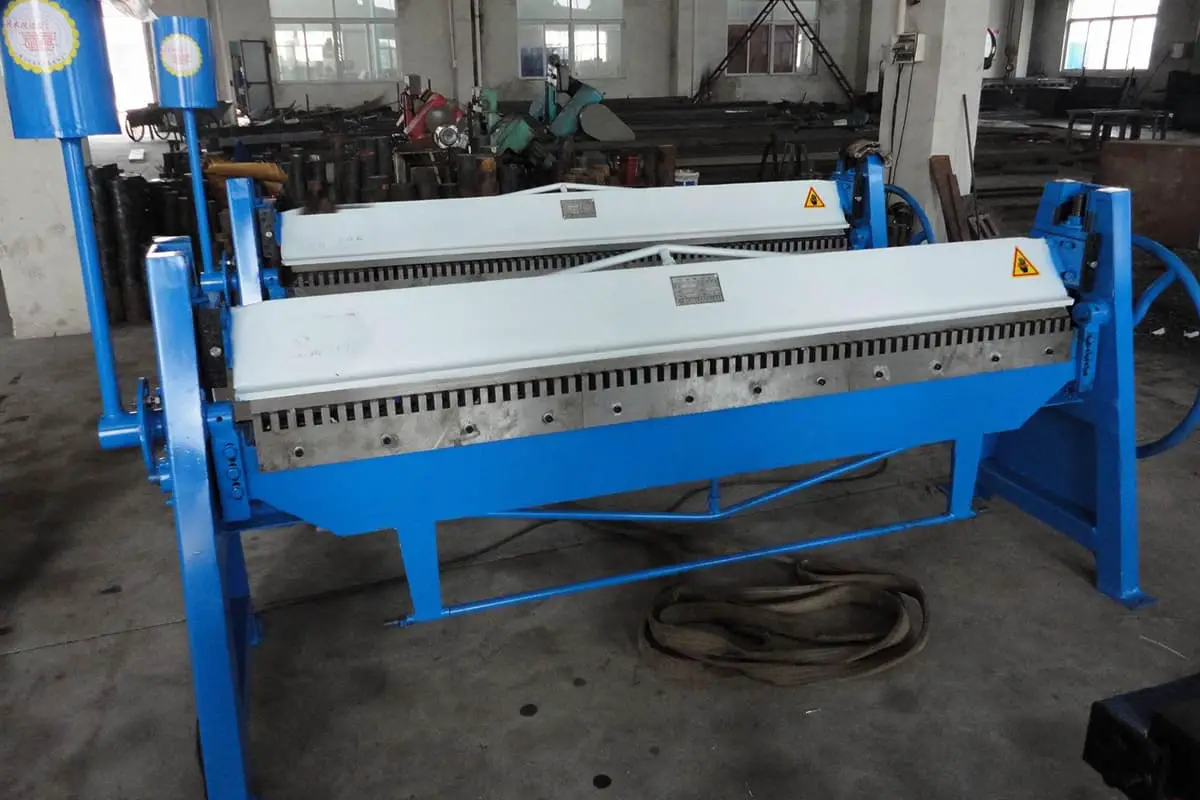
Pittsburgh lock former machine pictures
 |  |  |
|---|---|---|
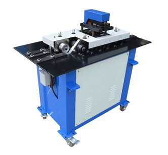
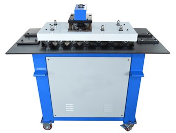
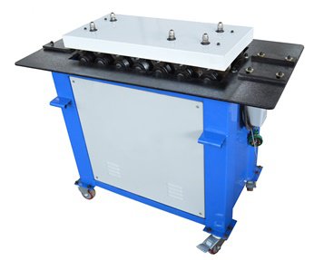
| Multi-function Nip Machine | Combined Elbow Nip Machine | Combined Nip Machine |
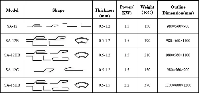
Model and Technical Parameters
Main Function and Performance
- The pittsburgh lockformer machine is specifically designed for producing various square or rectangle ventilation duct.
Our Pittsburgh Locking Machine is SA12-SA15HB.
Forming steel plate thickness 0.5-1.5mm (separately listed on Page 2- Machine Pictures). - With features of small size, lightweight, easy to move, simple operation and reliable, the pittsburgh lockformer machine is especially suitable for on-site manufacturing exhaust duct in industrial and mining, enterprises, hotels, shopping malls.
- Use cases
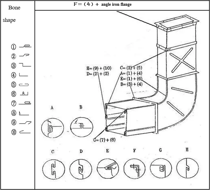
Fig.1
Pittsburgh Locking Machine Structure
Consists of the following three parts:
- A. Worktable
- B. Transferring and forming
- C. Elbow head
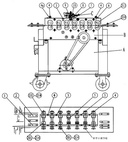
Fig.2
1) For single flat mouth, tighten the second upper bolt on right discharging port and loosen the right angel bolt.
Matters need attention:
① For SA-12—SA-15HB Pittsburgh locking machine, the thickness of side plate, double-screw bolt④, disc-shaped spring(4a)are adjustable. Four-bolts ③、④ are fixed.
A. Worktable
The trunk is a welded shell structure which is made by angle steel and thin steel sheet, with a fixed worktable panel on sheet top, the panel is equipped with horizontal lead-in positioning plates ①、② and four fixed lead-out positioning plates, see fig 2.
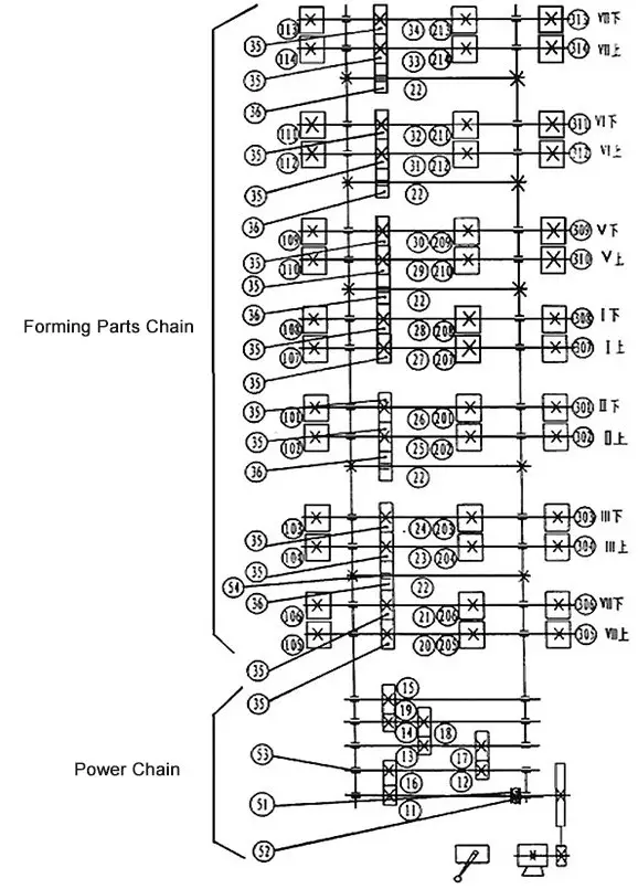
(Fig. 3)Transferring System
B. Conveying and Forming
The entire drive section is an open gearbox.
Passed through the gear shafts11, 12,13,14 and gears 16, 17, 18, 19 to the forming section, gear 19 separately drive Ⅲ down gear 35 and Ⅳ down gear 35, then through the multiple bridge gears driving the entire motion system.
Pittsburgh locking machines are generally equipped with 6 -7 pairs forming shafts, each pair shaft is equipped with a drive gear 35 and left and right two columns or left, center and right three columns of rolling reels.
(Fig. 3) is a comprehensive transmission diagram, however, not all machines are equipped with all the components listed in the fig, such as SA-12、SA-15、SA-12H、SA15 machine without 201-214 rolling reel.
C. Elbow Head
Structural Principal: (one fig.2 top), through bevel gear (5),(7) drive gear (10) and rolling reel (8)and(9), the workpiece will be put into the reel gap and forming fan-shaped workpiece into a certain height of the right angle bone, as shown in fig.1: E=(1)+(6)
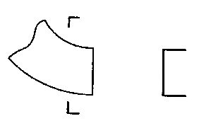
Fig.4
Elbow head is a dedicated part installed on the top of Pittsburgh Locking Machine ( as shown in fig.2: C), mainly used for right angle bone, that is, bending the fan-shaped plate into a certain height of right angle edge( see fig.4).
Connect this kind of right angle and “![]() ”shaped plate with a flange edge to make angle pipe connector.
”shaped plate with a flange edge to make angle pipe connector.
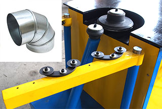
Each mode of Pittsburgh locking machine will be equipped with an elbow component according to the user demand, for example, change SA12C into SA12BC.
Adjustment and Use
The pittsburgh lock former machine can be used to connect or fold, but can’t roll, so when using the machine, some gap between the upper roller and lower roller is necessary, and the gap is about the minimum plate thickness plus 0.1-0.2 ( 3 ).
The gap has be adjusted before delivery, users should not arbitrarily rotate the limit screw (3) and fastening nut (4) and disc spring (4a)( as shown in fig.2 and 5).
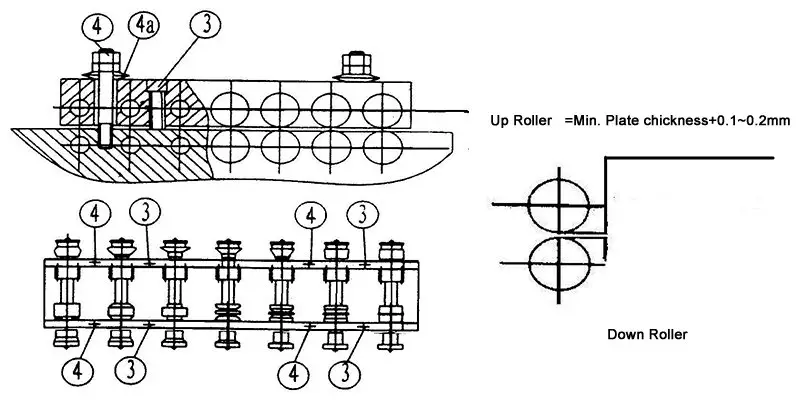
Fig.5
In case of the gap change due to screw (3), nut (4) becoming loosen, or caused by other reasons, first, loosen the nut (4), and put a pair of spacer of the same thickness as ![]() among the leftmost four groups of rollers, then adjust the limit screw (3) until the four gap basically parallel, re-lock the nut (4),[
among the leftmost four groups of rollers, then adjust the limit screw (3) until the four gap basically parallel, re-lock the nut (4),[![]() =Min. plate thickness+0.1-0.2mm], if minimum thickness, put the spacer and leave a slight space.
=Min. plate thickness+0.1-0.2mm], if minimum thickness, put the spacer and leave a slight space.
Right angle roller 300 part, manually adjust the roller and disc-shaped spring, keep the thin sheet “![]() ” shaped 90°.
” shaped 90°.
②Bone Shape Adjustment:
Loosen the screws (1) and (2) on leading-in positioning plate and move the guiding plate in horizontal direction to widen or narrow the forming parts. Wide plate ![]() , narrow plate
, narrow plate ![]() , wide plate
, wide plate ![]() ,narrow plate
,narrow plate ![]() .
.
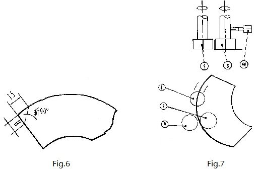
③Elbow use and adjustment ( fig. 7 )
First, bending the workpiece head into 90°,length 15mm, height H (SA15-HB H=10mm, others 8mm) (as shown in fig.6).
Then insert the B end among (8) and (9) in narrow direction ( as fig.7), then fasten screw (40), start the machine, hard push the plate along with the guide rotor into rolling roller.
Electrical Schematic Diagram ( 3-phase )
Here are the drawings:
Guiding Rule Adjustment Schematic Diagram
Here are the drawings:
Loved the post keep it up!