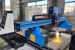
Have you ever considered how harmful the smoke and dust from plasma cutting can be? As plasma cutting becomes more prevalent, managing these pollutants is crucial to meeting environmental standards. This article explores effective methods for removing dust and smoke generated by plasma cutting machines, including both dry and wet treatment techniques. By implementing these strategies, you can ensure a safer and more efficient working environment. Dive in to discover how to keep your workshop clean and compliant.
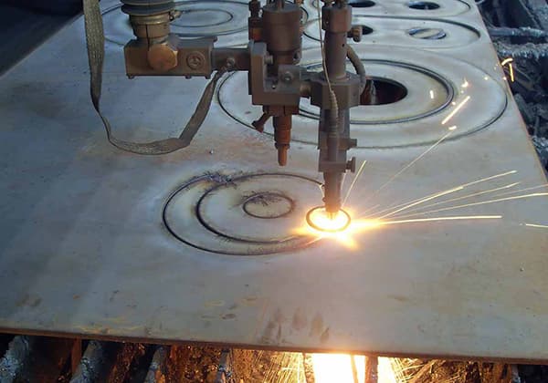
With the widespread use of plasma cutting machines, the smoke and dust produced during steel plate cutting pose a significant air pollution problem.
As environmental regulations become increasingly stringent, the persistence of smoke and dust in the workshop can result in the temporary closure of a factory for remediation.
It is imperative to implement a smoke and dust treatment method to address these waste gases.
This article provides an overview of the methods for treating smoke and dust generated from plasma cutting and aims to be informative and helpful.
For the treatment of dust generated by plasma cutting machines, there are two methods that can be employed: the dry treatment method and the wet treatment method.
Modern industry requires the processing of heavy metals and alloys. The manufacture of tools and transport vehicles necessary for daily activities can’t proceed without metals.
For instance, cranes, cars, skyscrapers, robots, and suspension bridges are all made from precisely processed metal components. The reason is simple: metal materials are very sturdy and durable.
For most manufacturing, particularly when it comes to large and/or sturdy items, metal materials become a logical choice.
Interestingly, the strength of metal materials is also their drawback: because metals are not easily damaged, it’s challenging to process them into specific shapes.

When people need to process a component that has the same size and strength as an airplane wing, how can precise cutting and shaping be achieved? In most cases, this requires the use of a plasma cutting machine.
Steel plates are one of the four primary forms of steel products, alongside tubes, profiles, and wire. In industrialized nations, plate production constitutes over 50% of total steel output. China’s steel plate production has been steadily increasing, aligning with its economic growth and industrial development.
Characterized by their large width-to-thickness ratio and substantial surface area, steel plates are categorized into two main specifications based on thickness: thin plates and thick plates.
Thin steel plates, produced through hot-rolling or cold-rolling processes, typically range from 0.2mm to 4mm in thickness. These plates find extensive applications in automotive body panels, appliance casings, and light structural components.
Thick steel plates, by definition, exceed 4mm in thickness. Industry practice further subdivides this category:
The width of thick steel plates generally spans from 600mm to 3000mm, accommodating various industrial needs. These plates are further classified based on their intended applications:
During World War II, American industrial productivity surged, outpacing Axis powers by a factor of five in the production of armor, weaponry, and aircraft. This remarkable feat was largely attributed to groundbreaking innovations in mass production techniques developed by private industries.
A critical aspect of these technological advancements was the pursuit of more efficient methods for cutting and assembling aircraft components. Many aerospace manufacturers adopted a novel welding technique involving inert gas shielding, which marked a significant leap forward in joining technology.
The pivotal discovery lay in the ability to create a protective barrier around the weld pool by ionizing gas through an electric arc. This shielding mechanism effectively prevented atmospheric contamination, particularly oxidation, resulting in cleaner welds and substantially stronger bonded structures. This innovation not only improved weld quality but also enhanced productivity in aircraft assembly lines.
In the early 1960s, engineers made another breakthrough in thermal cutting technology. They discovered that by constricting the orifice and accelerating the gas flow, they could dramatically increase the arc temperature. This new system achieved temperatures far exceeding those of conventional welding equipment, reaching upwards of 30,000°C (54,000°F).
At such extreme temperatures, the apparatus transcended its original welding function, evolving into a highly efficient cutting tool. The intensely focused plasma arc could slice through robust metals with remarkable ease and precision, comparable to a heated blade through a yielding substance.
The introduction of plasma arc cutting technology revolutionized metal fabrication processes. It dramatically improved cutting speed, precision, and versatility across a wide range of metals and thicknesses. Plasma cutting quickly became indispensable in industries ranging from automotive manufacturing to shipbuilding, offering capabilities that were previously unattainable with traditional oxy-fuel or mechanical cutting methods.
The ability of a plasma cutter to easily penetrate metal is due to the unique properties of the plasma state. So, what is the plasma state?
There are four states of matter in the world. Most of the substances we come into contact with in our daily lives are either solid, liquid, or gas. The state of a substance is determined by the interaction between its molecules. Take water as an example:
Solid water is ice. Ice is a solid formed by electrically neutral atoms arranged in a hexagonal crystal lattice. Due to the stable interaction between molecules, it maintains a solid shape.
Liquid water is the state we drink. There is still a force of interaction between the molecules, but they move at a slow speed relative to each other. Liquids have a fixed volume but no fixed shape. The shape of the liquid changes according to the shape of the vessel that holds it.
Gaseous water is water vapor. In water vapor, the molecules move at high speed and have no connection with each other. Since there is no force of interaction between the molecules, the gas has no fixed shape or volume.
The amount of heat (converted to energy) received by water molecules determines their properties and their state. Simply put, more heat (more energy) allows water molecules to reach a critical state where they can break free from the effects of their chemical bonds.
In a low heat state, the molecules bind tightly together, forming a solid. As they absorb more heat, the forces between them weaken, and they become a liquid. When they absorb even more heat, the forces between the molecules are almost completely lost, and they become a gas.
So, what happens if we continue to heat the gas? It reaches a fourth state: the plasma state.
When the gas reaches extremely high temperatures, it enters the plasma state. Energy begins to completely separate the molecules from each other, and atoms start to split.
A typical atom consists of protons and neutrons in the nucleus, surrounded by electrons. In the plasma state, the electrons separate from the atom.
Once the heat energy causes the electrons to leave the atom, they start moving at high speeds. The electrons carry a negative charge, while the remaining atomic nucleus carries a positive charge. These positively charged atomic nuclei are called ions.
When high-speed electrons collide with other electrons or ions, they release a tremendous amount of energy. It is this energy that gives the plasma state its unique properties, resulting in an incredible cutting ability.
In the universe, nearly 99% of matter exists in a plasma state. Due to its extremely high temperature, it is not commonly seen on Earth; however, it is very common on celestial bodies like the sun. On Earth, this state can be found in lightning.

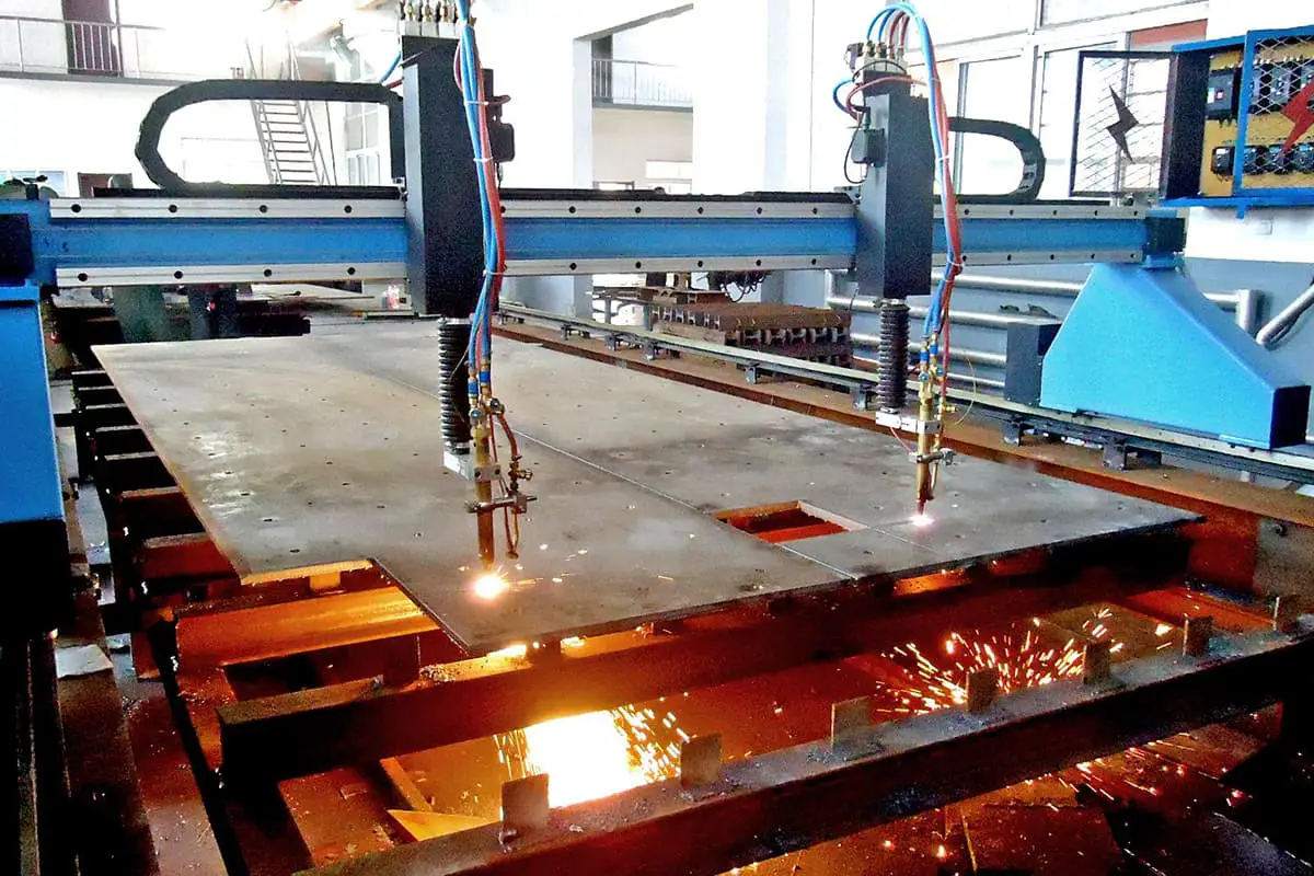
Plasma cutting machines come in a variety of shapes and sizes. There are large plasma cutting machines that use robotic arms for precise cutting, as well as simplified handheld plasma cutting machines used in manual workshops.
Regardless of size, all plasma cutting machines are based on the same principles and have similar structural designs.
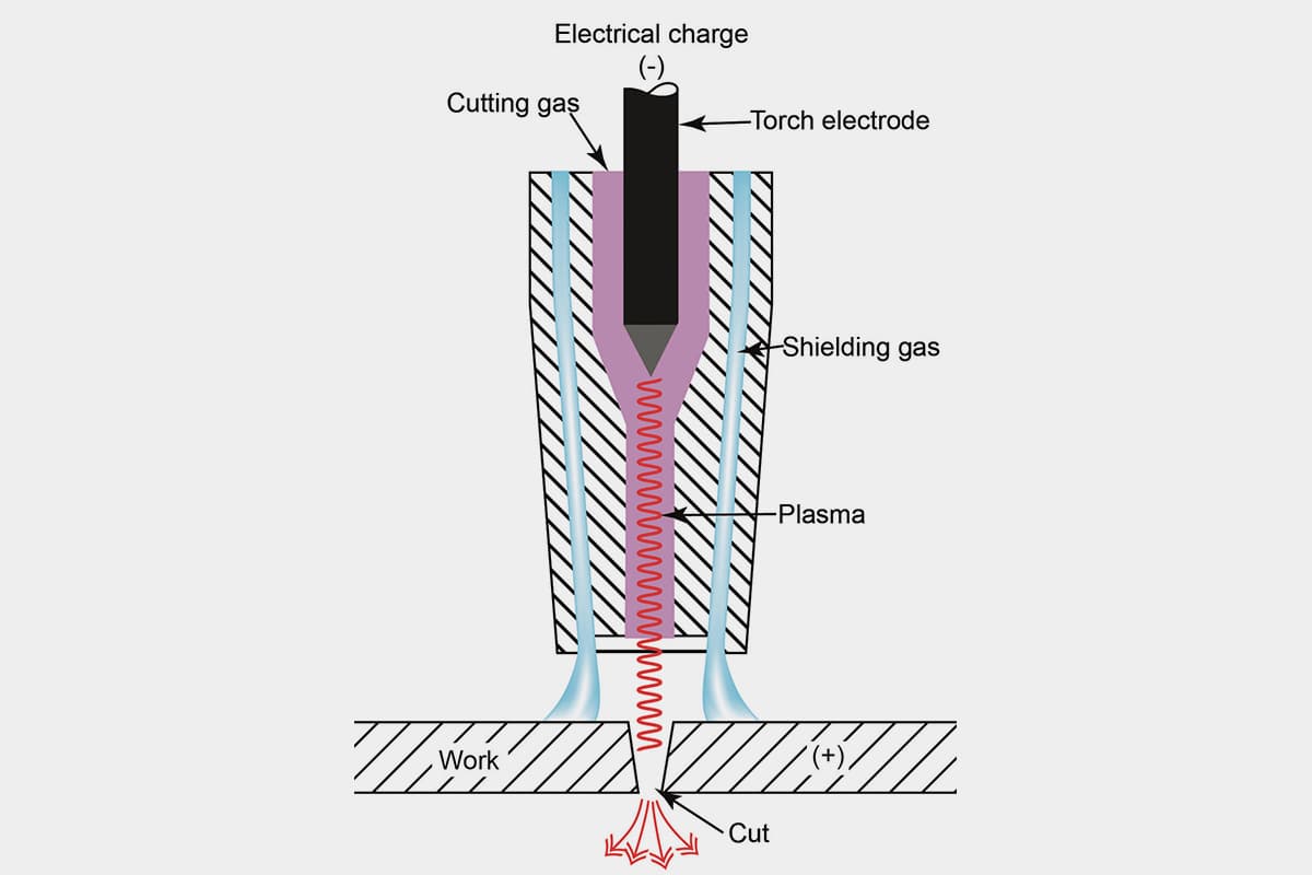
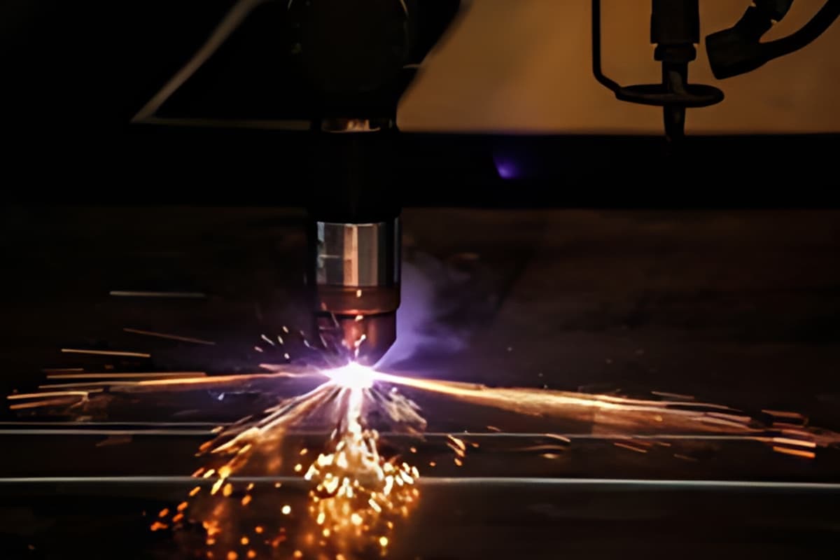
During the operation of a plasma cutting machine, compressed gases such as nitrogen, argon, or oxygen are sent through a narrow tube. A negative electrode is placed in the middle of the tube.
When power is supplied to the negative electrode and the nozzle touches the metal, a conductive circuit is formed, and high-energy electric sparks are generated between the electrode and the metal.
As the inert gas flows through the tube, the electric sparks heat the gas until it reaches the fourth state of matter. This reaction process produces a stream of plasma with a temperature of approximately 16,649 degrees Celsius and a velocity of up to 6,096 meters per second, which can quickly melt the metal.
The plasma itself has an electric current flowing through it. As long as power is continuously supplied to the electrode and the plasma remains in contact with the metal, the electric arc production cycle is continuous.
To ensure this contact while avoiding oxidation and damage caused by other unknown characteristics of the plasma, the cutting machine nozzle is equipped with another set of tubes. This set of tubes continuously releases shielding gas to protect the cutting area. The pressure of the shielding gas can effectively control the radius of the columnar plasma.
The thicker the steel plate to be cut, the greater the cutting current required.
Plasma Cutting Dust
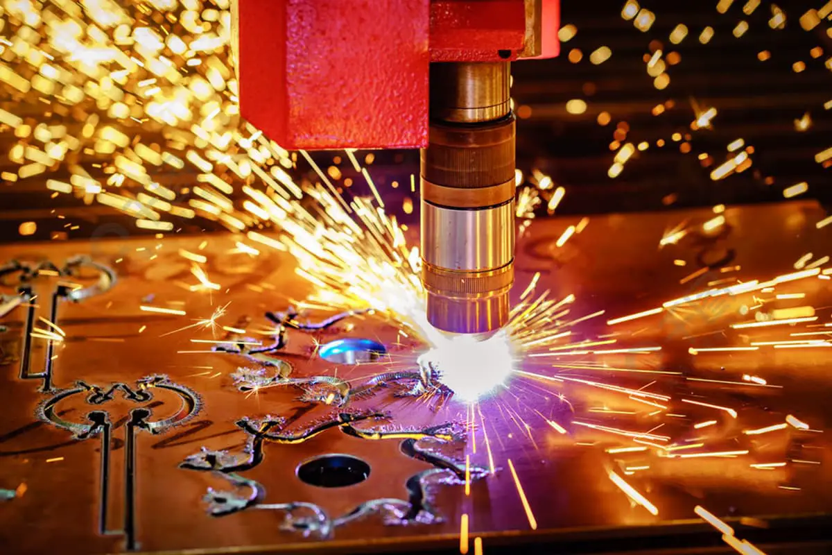
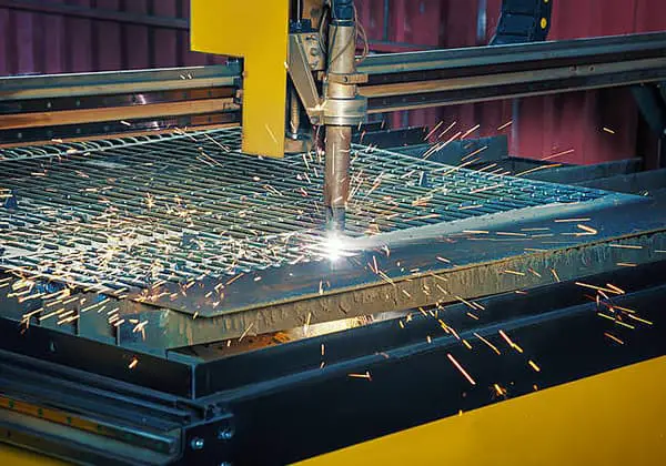
The plasma cutting process of metals generates significant quantities of smoke and particulate matter, comprising a complex mixture of hazardous substances. These emissions include metal oxides, volatile organic compounds (VOCs) such as acetaldehyde, sulfides, and various hydrocarbons. As these particulates are released into the air, they create substantial risks to both worker health and environmental safety.
The composition and concentration of these emissions vary depending on factors such as the material being cut, cutting parameters, and the presence of coatings or contaminants. For instance, cutting stainless steel may produce hexavalent chromium, a known carcinogen, while cutting galvanized steel can release zinc oxide fumes, potentially causing metal fume fever.
Prolonged exposure to these airborne contaminants can lead to the development of serious occupational diseases, including:
In severe cases, acute exposure to high concentrations of certain fumes can result in life-threatening conditions such as metal fume fever or acute respiratory distress syndrome (ARDS).
Given these significant health and environmental concerns, the implementation of effective dust and fume control measures for plasma cutting operations has become increasingly critical.
The wet treatment method in plasma cutting involves submerging the workpiece in a water bed positioned beneath the cutting machine. This technique effectively captures harmful byproducts generated during the cutting process, preventing their release into the atmosphere. The water acts as a barrier, trapping fumes, particulates, and other potentially hazardous substances.
While widely adopted in industrial settings, this method presents several challenges:
Despite these limitations, wet treatment remains a viable option for many applications due to its effective fume and noise reduction capabilities. To mitigate some drawbacks, advanced systems may incorporate water filtration, temperature control, and automated water level management features.
The dry treatment method involves collecting the smoke and dust produced during plasma cutting. There are several collection methods available, including side suction, lower suction, and upper suction. The smoke and dust are drawn into a pipeline by a fan and then purified using dust removal equipment before being discharged into the workshop or outside.
This method is constantly updated with the advancement of cutting machine technology. Previously, a movable suction cover was installed on the cutting head, but in practical applications, it was found that this was not effective in removing smoke and dust due to the narrow gap between the steel plate and the cutting position. Most of the smoke and dust is located in the lower part of the plate, and the upper dust suction cover is unable to effectively remove it.

A dust extraction work platform is installed beneath the cutting machine, equipped with a cutting fume purification system. This system directly transports the dust-laden smoke produced during cutting to the purifier for processing. The purified, up-to-standard gas is then discharged through the purifier’s exhaust vent.
Advantages: This setup prevents secondary pollution; dust cleanup is convenient; after cutting, the workpiece can directly proceed to the next process, thereby improving work efficiency. This system is suitable for non-ferrous metal cutting.
Disadvantages: Dust removal requires an investment, resulting in higher initial investment costs.

The dry processing dust removal system is composed of a dry cutting platform, dust removal pipeline, purifier, and fan, among other components. During cutting, the smoke and dust produced are captured by the dry cutting platform.
The platform’s air outlet is connected to the dust removal pipeline’s air inlet. Under the pipeline’s negative pressure, the cutting smoke and dust enter the dust removal pipeline and subsequently the purifier for purification.
Here, the cutting platform is a key component of the dust removal system.

The dust removal system can be categorized based on the method of capturing smoke and dust from the cutting platform into:
Damper Style Cutting Platform Dust Extraction System
Blowing and Suction Type Cutting Platform Dust Extraction System
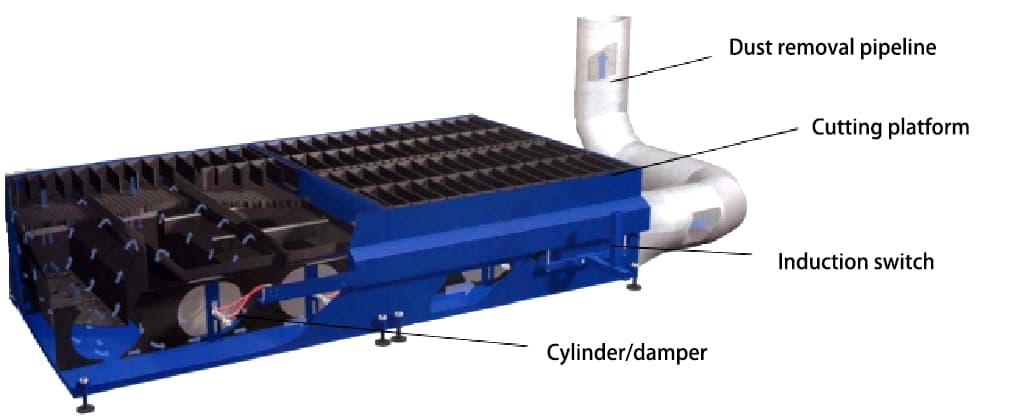
Working Principle: A louvered suction work platform is installed under the cutting machine, dividing the platform into several suction chambers of equal width along the length of the platform. Each suction chamber is fitted with a dust hopper with a suction port.
On both sides of the platform length, there are air ducts, each equipped with a louver and cylinder corresponding to each suction chamber on the side of the air duct. When the cutting head of the cutting machine moves over each suction chamber, the cylinder is controlled by the sensor switch to open the louver of the corresponding suction chamber on the air duct.
This process sucks in the smoke and dust produced during cutting into the dust removal air duct, before finally entering the main purifier for purification.
Structure of wind door cutting platform
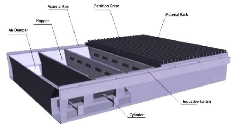

Features of the Louver-Type Cutting Platform Dust Removal System
The suction of the cutting platform effectively concentrates in the region where the cutting head is located (with a width equal to that of the cutting platform and a length of approximately 1m). This region moves with the cutting head, significantly saving the amount of suction.
Disadvantages:
Advantages:
The louver-type cutting platform is more suitable for dust removal applications where the platform width is less than 4m.
Calculation of the Suction Volume of the Louver-Type Cutting Platform Dust Removal System

The required suction volume of the louver-type cutting platform is greatly related to the cutting platform’s width. The calculation formula for the suction volume is as follows:
Q = W × 2 × 0.667 × υ × 3600
Where:
Affected by the structure of the cutting platform, for cutting platforms with an effective cutting width of less than 4m, a single-sided suction structure is generally adopted. For cutting platforms wider than 4m, a double-sided suction structure is used.
Single-sided/Double-sided Exhaust Cutting Platform CAD Structural Diagram and Exhaust Volume Calculation

Based on the equation above, if the width of the cutting platform is between 2m and 4m, the required exhaust volume Q = (2~4) × (0.8~1) × 3600 = 6000~12000 m 3/h.

If the cutting platform width is 4m~6m, then the required exhaust volume Q = (4~6) × (0.8~1) × 3600 = 12000~22000 cubic meters per hour.
Single-Sided / Double-Sided Exhaust Cutting Dust Removal System – Selection Table for Kaitian Dust Collector
| Cutting Platform Structure | Cutting Platform Width | Exhaust Volume(m3/h) | Dust Collector Model |
| Single-sided Exhaust Platform | 2000 | 6000 | KTJZ-6.OKQ |
| 3000 | 9000 | KTJZ-9.OKQ | |
| Double-sided Exhaust Platform | 4000 | 12000 | KTJZ-12KQ |
| 5000 | 20000 | KTJZ-20KQ | |
| 6000 | 24000 | KTJZ-24KQ |
Note: The above model selection is for reference only. Factors such as the length of the cutting platform, the number of plasma cutting heads, and the distance from the dust collector installation position to the cutting platform may affect the model of the dust collector. For specific model selection, please consult a Kaitian Environmental Protection sales representative.
Application Examples of Louver-style Dust Removal Systems


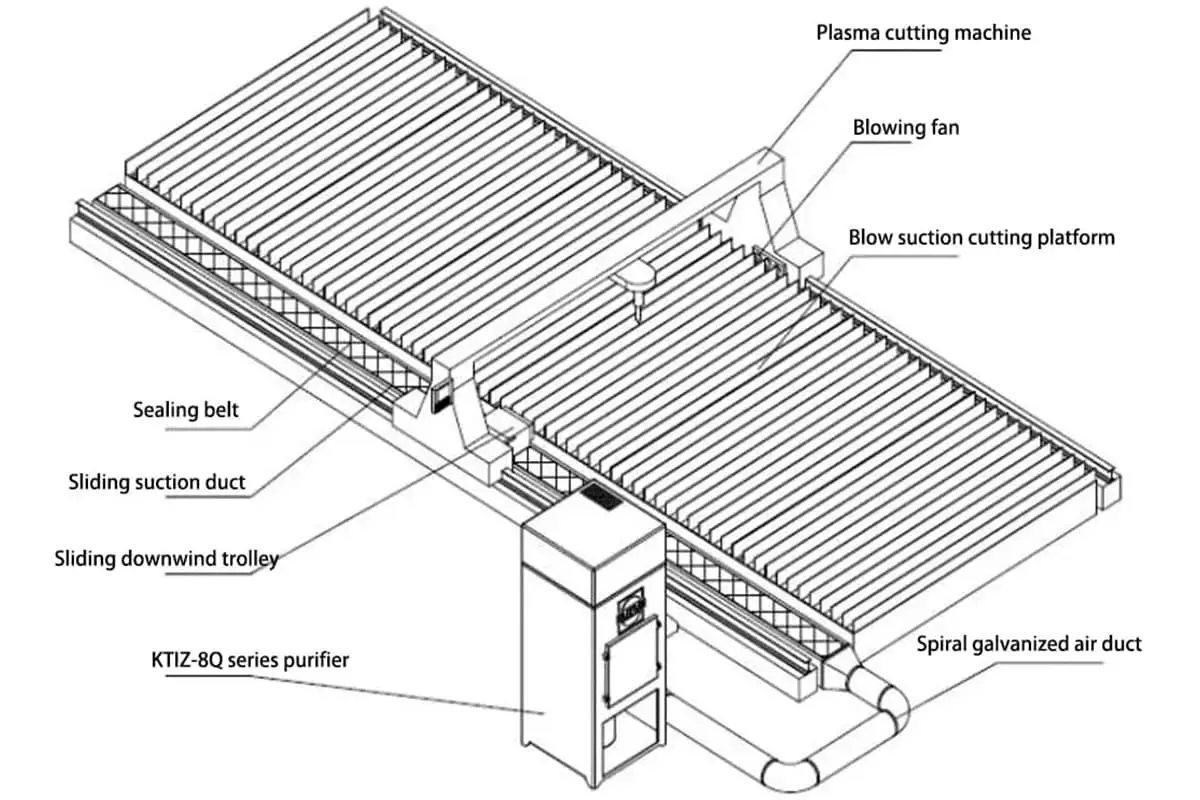
Working Principle: The system employs a dual-action approach combining directed airflow and strategic suction for efficient dust removal during metal cutting operations. A rectangular air intake duct is strategically positioned along one side of the cutting platform. This duct is complemented by a mobile air intake trolley that traverses above it, synchronizing its movement with the cutting machine’s motion.
On the opposite side of the cutting platform, a high-velocity air blower is installed. The linear alignment of the sliding air intake trolley, cutting head, and air blower along the transverse beam of the cutting machine creates an optimized flow path for dust extraction.
The cutting platform’s grid plate, in conjunction with the steel plate being processed, forms a controlled “fume channel”. During the cutting operation, the air blower generates a directional airflow that propels cutting dust and fumes through this channel. This contaminated air is then efficiently captured by the intake trolley, channeled into the rectangular duct, and subsequently conveyed to the central purification system for thorough filtration and treatment.
This integrated approach ensures comprehensive dust collection, minimizes atmospheric contamination, and maintains a cleaner working environment. The system’s design allows for consistent performance across various cutting patterns and workpiece sizes, enhancing both operational efficiency and workplace safety.

Structure of blow suction cutting platform
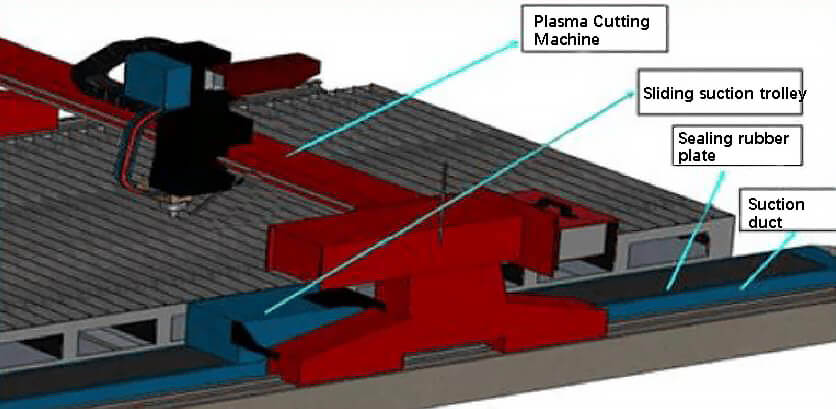
The structure of the blow-suction cutting platform involves a square suction duct and a sliding suction cart, which are crucial components. During operation, under the effect of negative pressure in the pipeline, the sealing belt closely adheres to the top of the square suction duct, serving a sealing function.
At the sliding suction cart, there are two rollers within the cart. The sealing belt is lifted when it passes through the cart. In this manner, the dust and smoke enter the square suction duct through the cart’s suction opening, and then proceed to the purifier for cleaning.


Features of the Blowing-Suction Cutting Platform Dust Removal System
The blowing-suction cutting platform has been widely used in recent years, with noticeable dust removal effects on cutting platforms over 4 meters.
Advantages:
Disadvantages:
Calculation of Exhaust Volume for Blow-Suction Cutting Platform Dust Removal System

The required exhaust volume for a blow-suction cutting platform is largely related to the coverage rate of the steel plate on the platform, thus the effect of coverage rate on exhaust volume should be comprehensively considered.
For a typical single slide duct blow-suction dust removal system:
Q = 6000~12000m3/h
For a double slide duct blow-suction dust removal system:
Q = 14000~24000m3/h
Due to the influence of cutting platform structure and suction duct size, single slide duct blow-suction dust removal systems are generally used for cutting platforms with effective cutting widths less than or equal to 5m; for those greater than 5m, double slide duct blow-suction dust removal systems are used.
Single/Double Sliding Air Duct Cutting Platform CAD Structural Diagram and Exhaust Volume Calculation

Based on the equation above:
For a cutting platform width ≤4.5m with a single sliding air duct, the required exhaust volume is Q = 6000~12000 m3/h.

The cutting platform width is greater than 4.5m, and it has dual sliding air ducts. Therefore, the required exhaust air volume is Q = 18000~24000m3/h.
Blow-Suction Schematic Diagram

Double Suction Schematic Diagram

Application Examples of Blow-Suction Dust Removal System


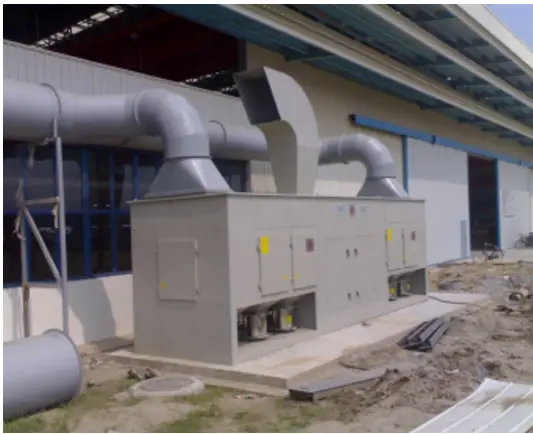
XCMG Site Video (Before the Dust Collector is Turned On)

XCMG On-site Video (After Dust Collector is Turned On)

Drag Chain Platform
1. Application of Drag Chain Platform:
2. Advantages of the Drag Chain Platform
The drag chain platform is sequentially divided into the roller conveyor feeding area, cutting area, and collection cleaning area. These three sections can operate simultaneously, thereby effectively improving the processing efficiency. The cutting slag can automatically fall off during the rolling process of the platform, avoiding manual shutdown for slag removal.
3. Use Case of Plate Chain Platform


