PLC Troubleshooting: 20 Years of Expertise Unveiled
Imagine your entire production line coming to a halt due to a malfunctioning PLC. Frustrating, right? This article dives into practical tips for troubleshooting PLC issues, helping you quickly identify and resolve problems. You’ll learn about input and output checks, program logic inference, and how to avoid common pitfalls. Whether you’re a seasoned engineer or new to the field, this guide offers valuable insights to keep your operations running smoothly.
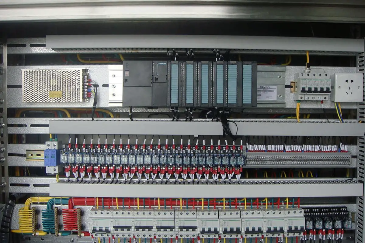
A small Programmable Logic Controller (PLC) flexibly controls a complex system. What you see are staggered rows of input and output relay terminal blocks, corresponding indicator lights, and PLC numbers, much like an integrated circuit with dozens of legs.
Without a schematic, anyone would be helpless in troubleshooting equipment, resulting in a significant slowdown in fault detection.
Given this, we create a chart based on the electrical schematic, posted on the equipment control panel or cabinet, indicating each PLC input and output terminal number, its corresponding electrical symbol, and its name, akin to the function description of each pin on an integrated circuit. With this input-output chart, electricians familiar with the operation process or the equipment’s ladder diagram can start troubleshooting.
For those unfamiliar with the operation process or unable to read ladder diagrams, an additional chart is needed: the PLC input-output logic function table. This table demonstrates the logical correspondence of most input circuits (trigger elements, associated elements) and output circuits (executing elements) during the operation process.
Experience shows that if you are proficient in using the input-output correspondence table and the input-output logic function table, you can easily troubleshoot electrical faults without a schematic.
PLC basic logic instructions
Describe
Mitsubishi
Siemens
OMROM
Loading, normally open contact at the beginning of the circuit
LD
LD
LD
Reverse loading, normally closed contact at the beginning of the circuit
LDI
LDN
LD NOT
And, normally open contact
AND
A
AND
Reverse And, Normally Closed Contact
ANI
AN
AND NOT
Or, normally open contact
OR
0
OR
Reverse or, Normally Closed Contact
ORI
ON
OR NOT
Block and
ANB
ALD
AND LD
Block or
ORB
OLD
OR LD
Output
OUT
=
OUT
Negate
INV
NOT
NOT
II. Input Circuit Troubleshooting
To determine the condition of a button, limit switch, line, or other input circuit, you can press the button (or other input contact) while the PLC is powered (preferably in non-operating state to prevent unintended equipment operation).
The button’s corresponding PLC input light should illuminate, indicating the button and line are operating normally. If the light does not come on, the button may be faulty, the line may have poor contact, or there may be a broken wire.
III. Output Circuit Troubleshooting
For PLC output points (considering relay output types here), if the corresponding indicator light for the actuator does not illuminate despite the PLC being in operation, it indicates that the PLC input-output logic function for this actuator has not been satisfied, suggesting a fault in the input circuit.
If the corresponding indicator light is on, but the corresponding actuator such as a solenoid valve or contactor does not operate, first check the solenoid valve control power and fuse.
If the light tester does not illuminate when measuring the common terminal of the corresponding PLC output point, there may be a power failure such as a blown fuse.
If the light tester illuminates, the power supply is good, suggesting a fault in the corresponding solenoid valve, contactor, or line.
After ruling out faults in the solenoid valve, contactor, or line and finding the system still not functioning normally, use a multimeter to connect one probe to the corresponding output common terminal, and the other to the corresponding PLC output point.
If the solenoid valve still does not operate, it indicates a fault in the output line. If the solenoid valve operates, then the problem lies with the PLC output point.
Given that a test pen can sometimes give false readings, an alternative method for analysis could be to measure the voltage between the PLC output point and the common end using a multimeter. If the voltage is zero or close to zero, it suggests that the PLC output point is operating normally and the fault lies externally.
If the voltage is relatively high, it indicates that the contact resistance of this point is too high and has been damaged. Moreover, when the indicator light doesn’t light up, but the corresponding solenoid valve or contactor is activated, it’s possible that this output point has been welded due to an overload or short circuit.
At this point, the wires connected to this output point should be removed, and the resistance between the output point and the common end should be measured using the resistance setting on the multimeter. If the resistance is low, it suggests this contact point is damaged. If the resistance is infinitely high, it means the contact point is good, and it’s likely that the corresponding output indicator light is faulty.
IV. Program Logic Inference
There are many types of PLCs commonly used in industry. For low-end PLCs, ladder diagram instructions are largely the same. For mid-to-high-end machines, like the S7-300, many programs are written in statement lists.
Practical ladder diagrams must have symbolic annotations; otherwise, reading becomes difficult. Understanding the equipment process or operation before looking at the ladder diagram makes it easier.
If analyzing an electrical fault, generally use the backtracking or reverse deduction method, i.e., starting from the fault point, find the corresponding PLC output relay and begin to backtrack the logic relationships that satisfy its operation.
Experience suggests that once a problem is found, the fault is usually rectified, as it’s rare for multiple faults to occur simultaneously.
V. Determining PLC Inherent Faults
Typically, PLCs are exceedingly reliable devices with a low failure rate. However, external factors can cause a PLC to malfunction. An incident occurred with a proximity switch powered by 220V. The two PLC signal input leads and the proximity switch’s 220V power line shared a four-core cable. When the switch faltered, the electrician replaced it but mistakenly swapped the neutral power line with the common line of the PLC input, leading to the burnout of three PLC input points upon power supply.
In another instance, the system power transformer’s neutral line was interrupted due to corrosion, causing the PLC’s 220V power supply to elevate to 380V. This damaged the power module at the base of the PLC. This was subsequently rectified by adding a 380/220V isolation control transformer. Siemens S7-200 PLC output common ends are labeled as 1L, 2L, etc., with the working computer represented as AC1N and the +24V power supply as L+M. This categorization can easily confuse beginners or those with less experience. Misinterpreting the L+M as a 220V power terminal could instantly burn out the PLC’s 24V power supply.
The probabilities of hardware components like PLCs and CPUs malfunctioning or software running astray are virtually negligible. Similarly, unless subjected to strong electric intrusion, PLC input points are unlikely to fail. The normally open points of the PLC output relays, barring peripheral load short circuits or poor design that lets the load current exceed its rated range, have a long life span.
Therefore, when troubleshooting electrical faults, the focus should primarily be on the peripheral electrical components of the PLC. Instead of constantly suspecting issues with the PLC hardware or software, this approach is crucial for quick repair of faulty equipment and rapid resumption of production. Thus, the emphasis in troubleshooting electrical faults in PLC control circuits is not on the PLC itself, but on the peripheral electrical components within the circuits controlled by the PLC.
As the founder of MachineMFG, I have dedicated over a decade of my career to the metalworking industry. My extensive experience has allowed me to become an expert in the fields of sheet metal fabrication, machining, mechanical engineering, and machine tools for metals. I am constantly thinking, reading, and writing about these subjects, constantly striving to stay at the forefront of my field. Let my knowledge and expertise be an asset to your business.
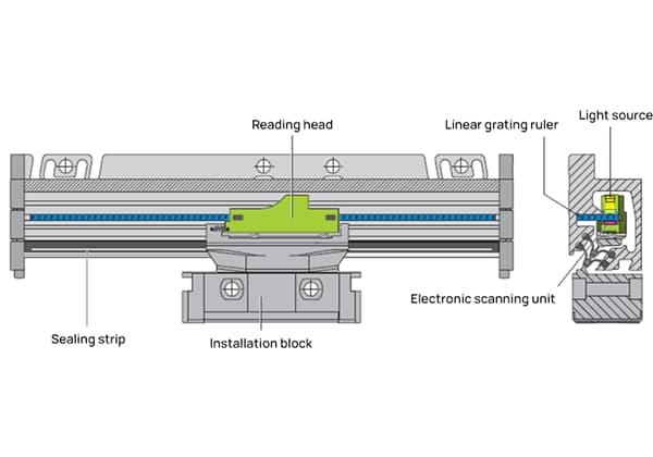
Imagine unlocking the precision of machine tools with a simple glass surface. Linear grating scales do just that, transforming fine lines into highly accurate measurements. This article explores how these…
Have you ever wondered how sharp edges on metal parts are smoothed out? This process, known as chamfering, transforms dangerous, jagged corners into safer, angled surfaces. In this article, you'll…
Have you ever wondered which bearing brands are the best in the world? In this blog post, we'll explore the top bearing manufacturers known for their exceptional quality, innovation, and…
Have you ever wondered who powers the world behind the scenes? In this blog post, we'll take a deep dive into the top generator manufacturers that keep the lights on…
Are you an aspiring mechanical engineer looking to excel in your field? In this blog post, we'll explore the top 10 must-know mechanical engineering design software that can elevate your…
Ever wondered how the integrity of welded nuts and screws in your car is ensured? This article reveals the meticulous process of quality checks and inspections that keep your vehicle…
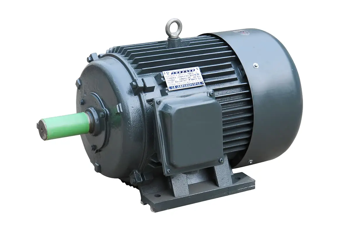
Have you ever wondered what keeps an electric motor running smoothly without overheating? Understanding the safe operating temperatures for motors is crucial for their longevity and performance. In this article,…
Have you ever wondered about the fascinating world of casting? This ancient yet ever-evolving manufacturing process shapes our daily lives in countless ways. In this blog post, we'll explore the…
Have you ever wondered how the gears in your car or airplane work so smoothly? This article unveils the top gear manufacturers shaping the future of mechanical engineering. You'll learn…