Have you ever wondered how machines convert invisible forces into powerful movements? In this blog post, we’ll explore the fascinating worlds of pneumatic and hydraulic transmissions. You’ll learn how these systems use air and liquid to power various machines, understand their components, and discover their unique advantages and challenges. Prepare to be captivated by the mechanics behind everyday technology!
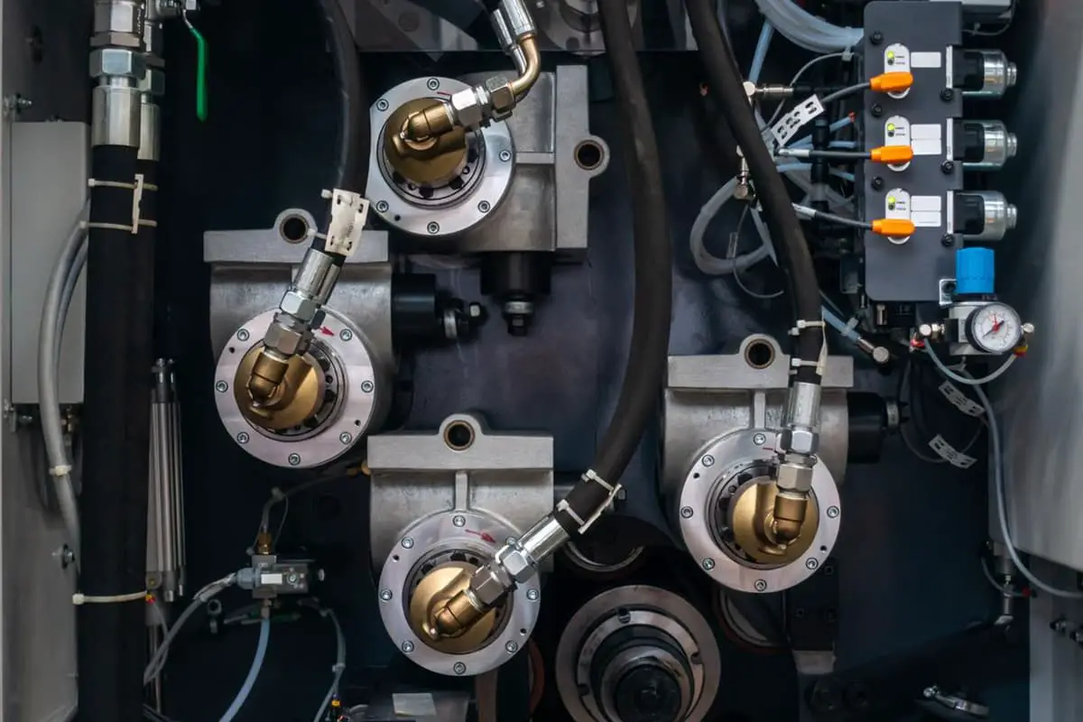

Pneumatic transmission is a sophisticated power transfer method that utilizes compressed gas, typically air, as the working medium to convey energy and control signals through a system. This technology harnesses the potential energy stored in pressurized gas to perform mechanical work and execute control functions.
The power transfer system in pneumatic transmission comprises several key components working in synergy. Compressed air, generated by compressors, is channeled through a network of pipes and regulated by precision control valves. This pressurized air is then directed to pneumatic actuators—such as cylinders, rotary actuators, or air motors—which efficiently convert the potential energy of the compressed gas into mechanical energy. This conversion enables a wide range of linear and rotary motions, making pneumatic systems highly versatile in industrial applications.
The information transmission aspect of pneumatic systems leverages the principles of fluid dynamics to perform complex logic operations and control functions. This is achieved through the use of pneumatic logic elements or fluidic devices, collectively forming what is known as a pneumatic control system. These elements, which may include AND gates, OR gates, and flip-flops, utilize the flow and pressure of the compressed air to process and transmit control signals. This pneumatic logic can be used to create sophisticated control schemes without the need for electrical components, offering robust performance in harsh or explosive environments where electronic systems may be unsuitable.
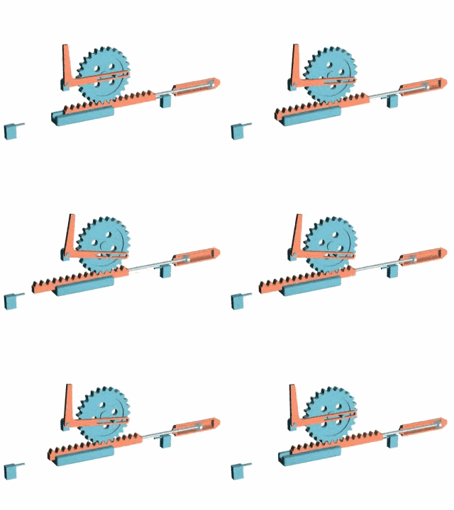
Pneumatic systems operate at relatively low working pressures, typically ranging from 0.3 to 0.8 MPa (43.5 to 116 PSI), offering distinct advantages in industrial applications. The low viscosity of compressed air results in minimal energy losses during transmission through pipelines, making these systems highly efficient for gas supply and transportation over moderate distances, generally up to 1000 meters.
One of the key benefits of pneumatic systems is their inherent safety. Unlike hydraulic or electrical systems, pneumatic setups pose no risk of explosion or electrical shock, even in the event of leaks or component failures. This safety aspect is particularly valuable in environments with flammable materials or where electrical sparks could be hazardous.
Furthermore, pneumatic systems feature built-in overload protection. When excessive load is applied, the system simply stalls without damaging components, unlike hydraulic systems which can build up dangerous pressures. This characteristic allows for simpler system design and reduced maintenance requirements.
However, it’s important to note that pneumatic systems require a reliable supply of compressed air. This necessitates the installation and maintenance of air compressors, air treatment units (for moisture and particulate removal), and storage tanks. While this infrastructure represents an initial investment, it often proves cost-effective in the long run due to the system’s efficiency and low maintenance needs.
Additionally, pneumatic systems offer excellent controllability and precision, making them ideal for applications requiring rapid, repetitive motions or delicate force control. They are widely used in manufacturing processes such as assembly, packaging, and material handling, where their speed, cleanliness, and adaptability provide significant advantages over other power transmission methods.
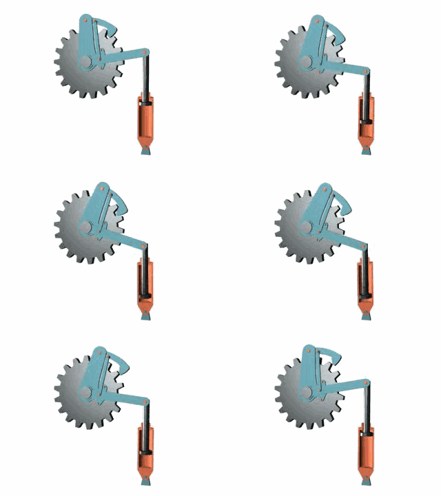
Pneumatic transmission systems consist of several key components working in synergy to convert compressed air into mechanical energy for various industrial applications. The primary elements include:
Air Source:
Typically supplied by air compressors, which pressurize ambient air to the required system pressure. Modern compressors often incorporate variable speed drives for enhanced energy efficiency.
Pneumatic Actuator:
These devices convert the potential energy of compressed air into mechanical work. Common types include:
Pneumatic Control Valves:
Critical for system control, these valves regulate air flow and are classified into:
Pneumatic Accessories:
Essential for system efficiency and longevity:
Sensors and Instrumentation:
Control Systems:
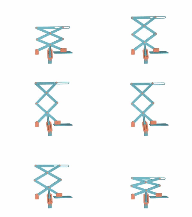
Pneumatic transmission utilizes compressed air as a medium, offering numerous benefits in industrial applications:
The inherent compressibility of air can adversely affect the dynamic stability of pneumatic systems, leading to performance variations under fluctuating loads. This characteristic often results in reduced operational precision and limitations on working speed, particularly in applications requiring rapid response times or consistent force output.
The relatively low operating pressure of pneumatic systems, typically ranging from 0.5 to 0.7 MPa (72 to 101 psi), constrains their ability to generate high force outputs and torque. This limitation makes pneumatic systems less suitable for heavy-duty applications or tasks requiring substantial power transmission, especially when compared to hydraulic or electromechanical alternatives.
Air-based control signal transmission exhibits longer response times compared to electronic or optical systems, which operate at or near the speed of light. This inherent latency renders pneumatic control less effective for high-speed, complex transmission systems or applications demanding real-time responsiveness, such as advanced robotics or precision manufacturing processes.
Pneumatic systems are often associated with significant noise generation, primarily due to the rapid expansion of compressed air during exhaust cycles. This noise pollution can be a concern in workplace environments, potentially necessitating additional soundproofing measures or personal protective equipment for operators.
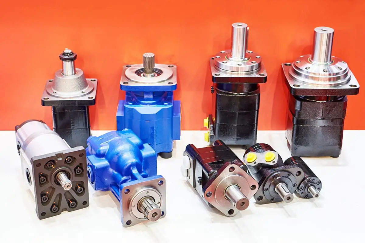
Hydraulic transmission is the transmission of energy and control by using the liquid as the working medium.
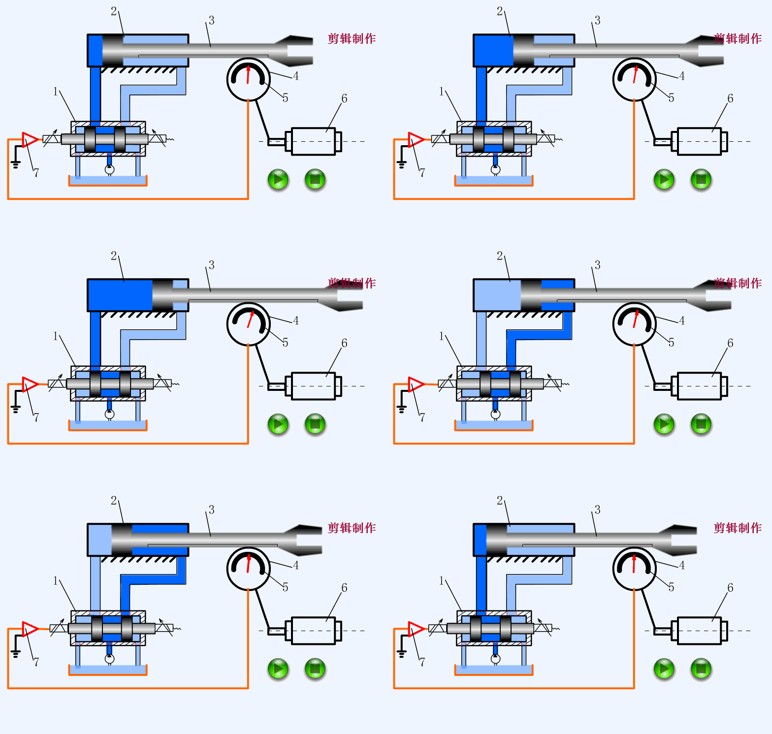
Hydraulic systems harness the power of fluid dynamics to efficiently convert, transmit, and apply energy in industrial applications. At their core, hydraulic pumps transform mechanical energy into hydraulic energy by pressurizing a fluid medium, typically mineral oil. This pressurized fluid serves as an energy carrier, capable of transmitting power over considerable distances with minimal loss.
The system’s circulatory network comprises precision-engineered components, including control valves, accumulators, and high-pressure pipelines. These elements work in concert to regulate fluid flow, pressure, and direction. The controlled fluid is then directed to hydraulic actuators—such as cylinders for linear motion or motors for rotational output—where the hydraulic energy is reconverted into mechanical force and motion.
This versatile power transmission method enables both precise linear reciprocation and smooth rotary motion, making it ideal for applications ranging from heavy machinery to delicate robotics. The working medium, most commonly mineral oil, is chosen for its incompressibility, lubricating properties, and thermal stability. However, environmentally friendly biodegradable fluids are gaining traction in certain applications.
Hydraulic systems offer several advantages over traditional mechanical transmission elements like belts, chains, and gears, including higher power density, smoother operation, and the ability to transmit force over complex paths. Moreover, they provide excellent control over force and speed, making them indispensable in modern manufacturing and mobile equipment.
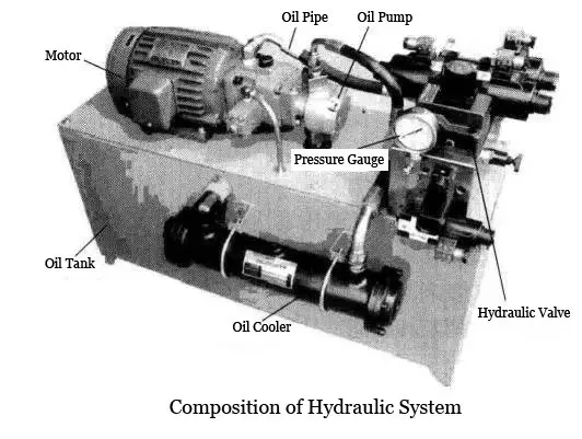
The hydraulic system is a critical component in many industrial applications, particularly in metal forming processes. It comprises several key elements working in synergy to transmit power and control motion with precision:
Hydraulic pump:
The heart of the system, converting mechanical energy into hydraulic energy by pressurizing fluid.
Hydraulic control valve:
Regulates the flow and direction of hydraulic fluid, enabling precise control over actuator movements.
Hydraulic actuators:
Convert hydraulic energy into mechanical force and motion. These include:
Auxiliary components:
Essential for system efficiency and reliability, including:
Press brake machines exemplify the effective utilization of hydraulic transmission in metal forming. These machines leverage hydraulic power to generate high forces necessary for precise bending of metal sheets. The system’s ability to provide controlled, variable force throughout the bending stroke ensures accuracy and repeatability in producing complex shapes.
Modern hydraulic systems in metal fabrication often incorporate advanced features such as closed-loop control, proportional valves, and digital interfaces, enhancing precision, energy efficiency, and integration with automated production processes.
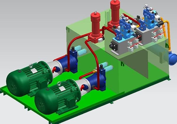
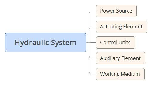
The hydraulic system comprises several critical components, each playing a vital role in the efficient conversion and transmission of energy:
Power components, primarily hydraulic pumps, serve as the system’s heart. They convert mechanical energy into fluid kinetic energy, generating both pressure and flow. These pumps supply pressurized oil to the entire hydraulic system, acting as the primary power source.
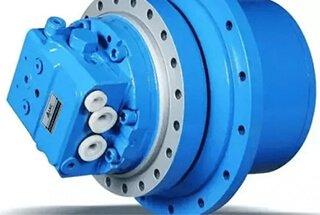
Actuators, including hydraulic cylinders and motors, function as the system’s muscles. They convert hydraulic energy back into mechanical energy through near-isothermal processes. Hydraulic cylinders produce linear reciprocating motion, ideal for tasks like lifting or pressing. Hydraulic motors, on the other hand, generate rotational motion, suitable for applications requiring continuous turning force.
Control elements form the system’s nervous system. This category encompasses various components designed to regulate and adjust fluid pressure, flow rate, and direction within the hydraulic circuit. These elements ensure that actuators perform precisely according to specified requirements, enabling complex and coordinated movements.
Auxiliary components, while often overlooked, are crucial for system integrity and performance. This category includes:
The working medium, typically specialized hydraulic oil, acts as the system’s lifeblood. Beyond its primary role in energy transmission, this fluid also lubricates moving parts, dissipates heat, and often carries away contaminants. The choice of hydraulic oil significantly impacts system efficiency, component longevity, and overall performance.
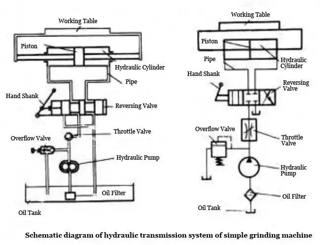
Here is an example of a simple hydraulic grinder:
The electric motor drives the hydraulic pump, drawing oil from the reservoir and converting mechanical energy into hydraulic pressure energy. This pressurized fluid serves as the power medium for the entire system.
The hydraulic fluid enters the left chamber of the hydraulic cylinder through a flow control valve (throttle valve) and directional control valve (reversing valve). This action forces the piston to move, driving the table to the right. Simultaneously, fluid in the right chamber is displaced and returns to the reservoir.
When the directional control valve shifts, the hydraulic fluid is redirected to enter the right chamber of the cylinder. This causes the piston to move leftward, retracting the table.
The velocity of the hydraulic cylinder’s movement can be precisely controlled by adjusting the opening of the flow control valve. This allows for fine-tuning of the grinding process speed.
System pressure is regulated using a pressure relief valve (overflow valve), which helps maintain consistent force and protects the system from excessive pressure.
In hydraulic system schematics, standardized symbols known as functional symbols are used to represent various components. These symbols provide a clear, concise way to illustrate complex hydraulic circuits and their functions.
This hydraulic transmission system exemplifies the principles of fluid power, demonstrating how hydraulic energy can be efficiently controlled and applied in precision machining operations.
Basic circuit
A typical hydraulic transmission system comprises various hydraulic components that work together to achieve specific functions.
Any hydraulic transmission system is made up of several basic circuits, each with specific control functions. By combining these basic circuits, the movement direction, work pressure, and movement speed of the actuator can be controlled.
Based on their control function, the basic circuit is divided into three types: the pressure control loop, speed control loop, and direction control loop.
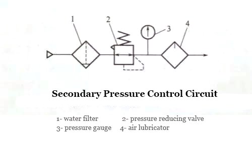
① The pressure control circuit
The pressure control valve is used to control the entire system or a local range pressure circuit.
Based on their function, the pressure control circuit can be divided into four circuits: pressure adjustment, pressure change, pressure release, and pressure stabilization.
② Speed control loop
This loop controls the flow rate of the actuator by regulating the flow of the hydraulic medium. The function of the speed control loop is divided into two parts: the speed regulation circuit and the synchronization loop.
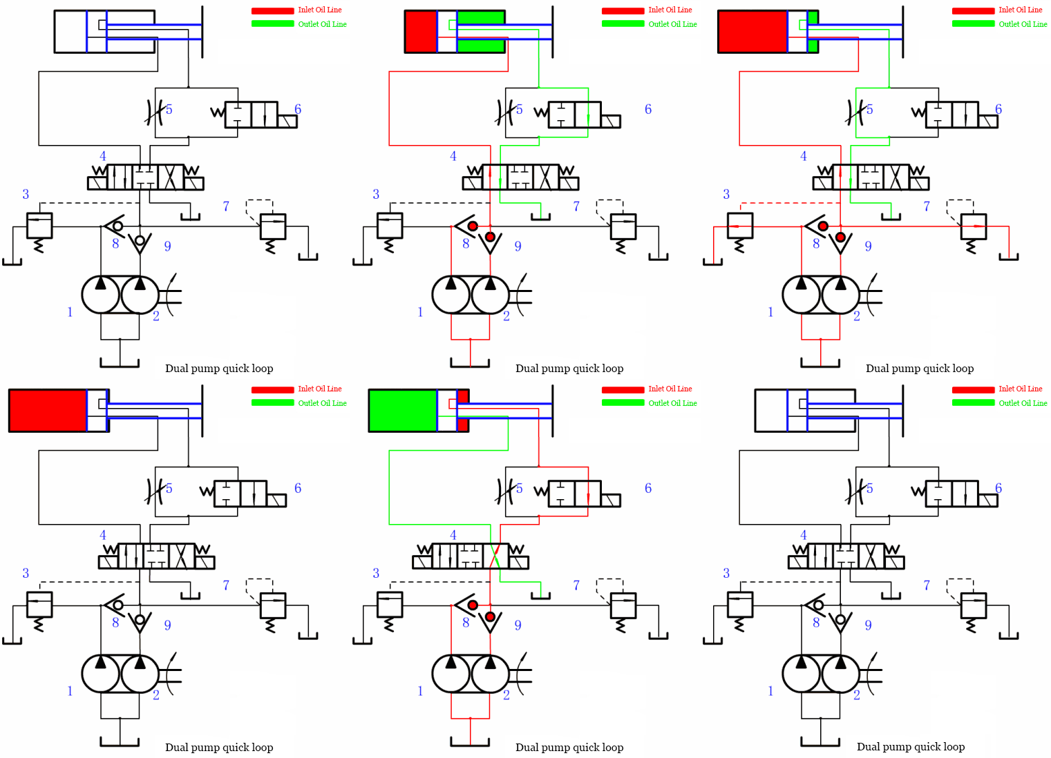
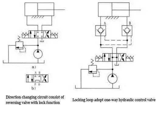
③ Direction control loop
This loop controls the flow direction of the hydraulic medium. The directional control valve controls the movement direction of a single actuator, allowing it to move or stop in both positive and negative directions, which is known as a commutator circuit.
When the actuating element stops, the circuit that prevents external leakage due to loading or other external factors is called a locking loop.
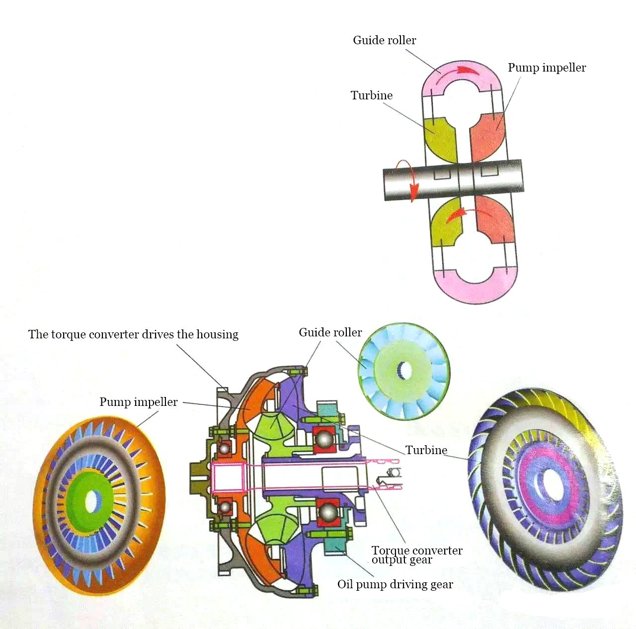
Hydraulic transmission involves the transfer of energy through liquid kinetic energy, using liquid as the working medium.
The impeller converts the rotational speed and torque input from an engine (such as an internal combustion engine, motor, turbine, etc.) and drives the machine’s working parts via the output shaft.
The fluid and impeller interact with each other in the input shaft, output shaft, and shell, producing a change in the moment of momentum to transmit energy.
Hydraulic transmission differs significantly in principle, structure, and performance from fluid pressure-based hydraulic transmission.
The input shaft and output shaft of the hydraulic drive are only connected to the working medium through liquid, and non-direct contact between components results in non-rigid transmission.
Characteristics of hydraulic drive
Automatic adaptability
The hydraulic torque converter can automatically increase or decrease its output torque with changes in external loads, and the speed can correspondingly increase or decrease, achieving stepless speed regulation within a wide range.
Vibration isolation
Because the working medium between the impeller is liquid, their connection is not rigid, making it possible to absorb shock and vibration from the engine and external load. This ensures stable starting, acceleration, and uniform operation, extending the service life of parts.
Penetration performance
When the pump rotation speed is constant and the load changes, the input shaft (i.e., the pump wheel or engine shaft) changes.
Different types of hydraulic elements can be used to match the engine’s requirements for different work machines, improving mechanical power and economic performance.
The basic principle of hydraulic drive
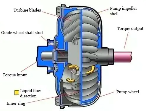
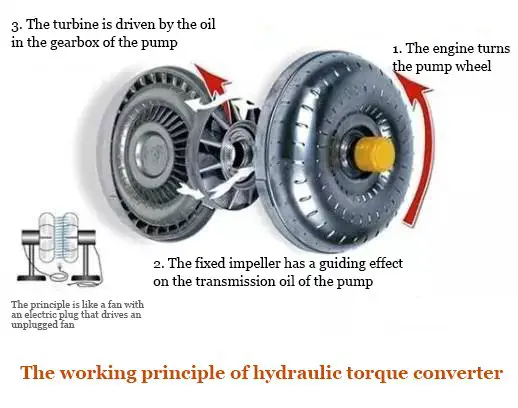
The original power source (such as an internal combustion engine, motor, etc.) drives the pump wheel to rotate, increasing the speed and pressure of the working fluid and converting mechanical energy into liquid kinetic energy.
The working liquid, now with kinetic energy, hits the turbine and releases energy to the turbine, causing it to turn and power the output, ultimately transferring energy.
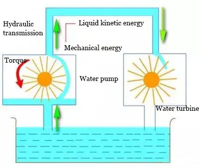
Hydraulic transmission utilizes liquid kinetic energy to transfer energy, and it commonly includes hydraulic couplers, hydraulic torque converters, and hydraulic mechanical components.
① Hydraulic coupler
A hydraulic coupler, also known as a hydraulic coupling, is a mechanical device used to connect a power source (usually an engine or motor) to a working machine to deliver rotational power.
In addition to use in automobiles’ automatic transmissions, hydraulic couplers are widely used in marine and heavy industries.

② Torque converter
A hydraulic torque converter is a hydraulic element that consists of a pump wheel, turbine, and guide wheel. It is installed between the engine and transmission and uses hydraulic oil as the working medium to transmit and convert torque, adjust speed, and provide disconnection functionality.
Application of hydraulic drive
The use of hydraulic transmission in modern machinery began in the early 20th century, primarily as ship power equipment and transmission mechanisms between the propellers to solve the issue of limited speed due to high power and high-speed steam or gas turbines suffering from “cavitation.”
Today, hydraulic transmission is widely used in automobiles, tractors, construction machinery, railway locomotives, tank armored vehicles, oil drilling machinery, lifting and transportation machinery, fans, pumps, and other equipment.

