Top 10 Best CNC Controller Brands in the World
Have you ever wondered what powers the precision and automation of modern manufacturing? In this article, we dive into the world of CNC systems, the brains behind the machines that…
Imagine slicing through metal with precision so fine it feels like cutting through butter. This article dives into the world of CNC electrical discharge wire cutting, explaining how it uses sparks to shape metal with remarkable accuracy. By exploring the principles behind the pulsed discharges, wire movements, and coordinate adjustments, you’ll uncover the technology that makes intricate designs and high-quality finishes possible in modern manufacturing. Get ready to learn how this fascinating process works and how it revolutionizes metalworking.
The process of electrical discharge CNC wire cutting mainly includes the following three parts (as shown in Figure a):
(1) Pulsed discharge between the electrode wire and the workpiece.
(2) The electrode wire moves along its axial direction (vertical or Z direction).
(3) The workpiece makes CNC movement relative to the electrode wire in the X, Y plane.

During electric spark wire cutting, the electrode wire is connected to the negative pole of the pulse power supply, and the workpiece is connected to the positive pole. A pulse power source is applied between the positive and negative poles.
When a pulse arrives, a spark discharge is generated between the electrode wire and the workpiece. The temperature in the middle of the discharge channel can instantaneously reach above 10,000°C, causing the metal of the workpiece to melt, and even a small amount to vaporize.
The high temperature also causes part of the working fluid between the electrode wire and the workpiece to vaporize. This vaporized working fluid and metal vapor heat expand instantaneously and have explosive characteristics.
This thermal expansion and local micro-explosion throw out the melted and vaporized metal material, realizing the electric erosion cutting of the workpiece material. It is generally believed that the discharge gap between the electrode wire and the workpiece is about 0.01mm. If the voltage of the pulse is high, the discharge gap will be larger.
For the smooth progress of electric spark processing, it is necessary to create conditions to ensure that each pulse produces a spark discharge, not an arc discharge, between the electrode wire and the workpiece.
First, there must be enough interval time between two pulses to allow the medium in the discharge gap to deionize, i.e., to make the charged particles in the discharge channel recombine into neutral particles, restore the insulating strength of the medium in the gap at this discharge point, and avoid continuous discharge at the same point leading to arc discharge. The general pulse interval should be more than four times the pulse width.
To ensure that the electrode wire is not burned during spark discharge, a large amount of working fluid must be injected into the discharge gap so that the electrode wire can be fully cooled. At the same time, the electrode wire must move quickly in the axial direction to avoid being burned by continuous spark discharge at a local position.
The speed of the electrode wire is approximately 7~10m/s. The high-speed moving electrode wire is beneficial for constantly bringing new working fluid into the discharge gap and for removing the electric erosion products from the gap.
During electric spark wire cutting, in order to obtain a good surface roughness and high dimensional accuracy, and to ensure that the electrode wire is not burned, the appropriate pulse parameters should be selected, and the discharge between the workpiece and the molybdenum wire must be a spark discharge, not an arc discharge.
To prevent spark discharges from burning the electrode wire at the same spot, which can impact the quality and efficiency of the process, the electrode wire moves along the axis during the cutting process.
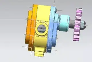
The principle of wire feeding is illustrated in Figure b. The molybdenum wire is neatly wound on the wire storage drum, forming a closed loop. When the wire feed motor drives the wire storage drum to rotate, the molybdenum wire moves along the axle through the wire guide wheel.

The workpiece is mounted on the X, Y coordinate worktable of the upper and lower layers, each driven by a stepper motor for numerical control motion. The motion trajectory of the workpiece relative to the electrode wire is determined by wire cutting programming.

As the founder of MachineMFG, I have dedicated over a decade of my career to the metalworking industry. My extensive experience has allowed me to become an expert in the fields of sheet metal fabrication, machining, mechanical engineering, and machine tools for metals. I am constantly thinking, reading, and writing about these subjects, constantly striving to stay at the forefront of my field. Let my knowledge and expertise be an asset to your business.