Resolução de problemas de descida da prensa dobradeira: Causas e soluções
Já se perguntou porque é que a sua prensa dobradeira não está a descer em sincronia? Este artigo analisa as causas comuns da dessincronização em prensas dobradeiras hidráulicas, tais como fugas internas no cilindro do pistão e problemas na tubagem de óleo. Também oferece soluções práticas, garantindo que a sua máquina funciona de forma suave e eficiente. Saiba como resolver e corrigir estes problemas para manter a qualidade e a produtividade dos seus processos de metalurgia.
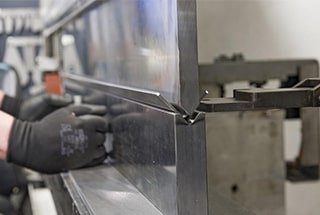
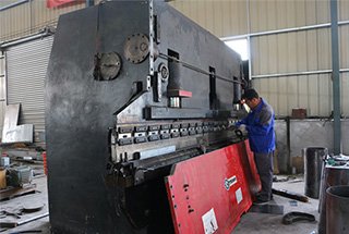
A prensa dobradeira hidráulica WC67Y-250/4000 foi concebida para dobrar chapas metálicas com elevada produtividade de trabalho e precisão de dobragem. Oferece estabilidade, fiabilidade e facilidade de operação, com opções de deslocamento gradual ou contínuo.
Esta prensa dobradeira hidráulica mantém uma pressão consistente ao longo de todo o curso de trabalho, assegurando uma distribuição uniforme da força. Os utilizadores podem facilmente equipá-la com diferentes moldes para atingir os objectivos pretendidos. dobragem de chapa forma.
No entanto, é importante notar que a velocidade do movimento de retorno desta prensa dobradeira é várias vezes mais rápida do que o processo de dobragem, permitindo uma maior eficiência na produção. No entanto, é crucial garantir que o cilindro da travão de prensa não caia demasiado depressa, fazendo com que fique fora de sincronia e afectando potencialmente a qualidade do produto final.
2. Análise da causa da dessincronia
1) Análise do cilindro de pistão:
A principal razão para o problema é uma fuga interna no cilindro do pistão. A folga entre o pistão e o cilindro de óleo é demasiado grande, causando fugas. No entanto, a fuga nos cilindros esquerdo e direito não é uniforme, o que resulta em diferentes velocidades de movimento dos dois cilindros.
2) Análise da conduta de entrada de óleo:
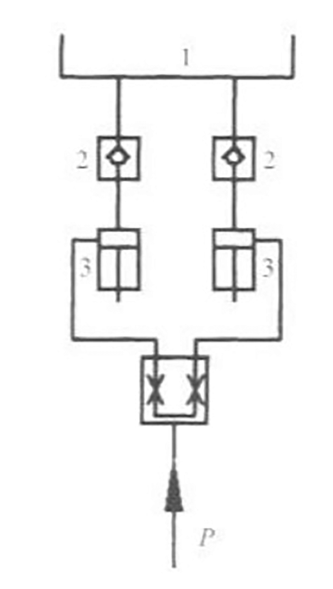
A figura 1 ilustra o processo de travão de prensa descendo rapidamente. A bomba de óleo fornece óleo ao cilindro de óleo através da válvula síncrona, enquanto que o depósito de óleo superior 1 fornece óleo ao cilindro de óleo através da válvula unidirecional 2, devido à diferença natural de altura. Estes dois tipos de óleo fornecem óleo para a câmara superior do cilindro de óleo, o que faz com que o cilindro de óleo desça rapidamente.
Devido ao fluxo aproximado no circuito da válvula após a válvula de sincronização, apenas o fluxo do tanque através da válvula de retenção 2 para o cilindro de óleo 3 é levado em consideração.
1- Depósito de óleo; 2 - Válvula de retenção; 3 - Cilindro de óleo.
Fig. 1 Análise da alimentação de óleo do cilindro de óleo
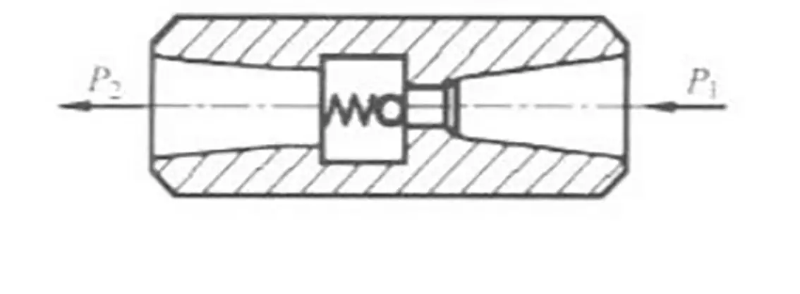
A figura 2 mostra a estrutura da válvula de retenção 2.
P1 representa a pressão de entrada, enquanto P2 representa a pressão de saída.
Considerando a pressão de entrada para ambas as válvulas de retenção, P1 pode ser considerada como pressão atmosférica, tornando-as iguais.
Dado que P1 é constante, o caudal Q através da válvula de retenção aumenta com um aumento da diferença de pressão (P-P2).
Fig. 2 Estrutura da válvula de retenção
Do que precede resulta que os dois cilindros hidráulicos não estarão completamente sincronizados no arranque. Como resultado, a pressão na câmara superior dos dois cilindros, indicada como P, não será a mesma. Esta diferença de pressão entre a frente e a traseira das duas válvulas de retenção também não será a mesma.
Consequentemente, o fluxo do cilindro de óleo através da válvula unidirecional para os dois cilindros não será igual. Este desequilíbrio de caudal provoca a dessincronização do movimento dos dois cilindros.
3) Análise da conduta de retorno do óleo:
Quando a prensa dobradeira desce rapidamente, o amortecimento do movimento no circuito do óleo de retorno pode não ser igual, causando uma diferença na contrapressão na câmara inferior do pistão. Consequentemente, o caudal de retorno dos dois cilindros pode não ser o mesmo, o que faz com que a velocidade de descida rápida dos dois cilindros seja desigual e, portanto, dessincronizada.
3. Solução
(1) Para garantir fugas iguais em ambos os cilindros hidráulicos, é importante manter a consistência na precisão da seleção dos pistões, cilindros e outras peças da esquerda e da direita (incluindo precisão dimensional e precisão de posição, como a coaxialidade), redondeza, etc.). Além disso, os circuitos hidráulicos dos dois cilindros hidráulicos devem ser concebidos da forma mais semelhante possível.
(2) Para garantir um fluxo igual através das duas válvulas de retenção na tubagem de entrada de óleo, é necessário procurar que o centro de gravidade da estrutura móvel esteja localizado no centro geométrico dos dois cilindros. Além disso, o amortecimento mecânico entre o êmbolo e a haste do êmbolo e entre a haste do êmbolo e a tampa da extremidade deve ser tão próximo quanto possível para assegurar um amortecimento mecânico semelhante dos dois cilindros de êmbolo quando caem rapidamente.
(3) Para a tubagem de retorno do óleo, é necessário assegurar que o fluxo de retorno dos dois cilindros é igual, tornando a resistência do óleo de retorno da tubagem de retorno do óleo semelhante. Para tal, é necessário assegurar que o diâmetro e o comprimento do tubo são iguais, curvatura de tubos e o ângulo de curvatura do tubo são basicamente os mesmos.
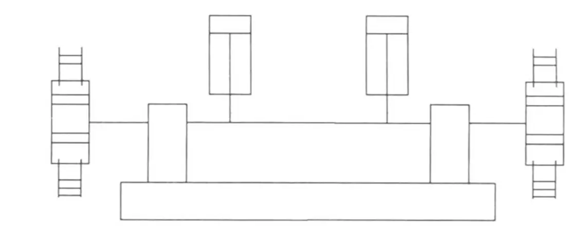
(4) A prensa dobradeira utiliza um acionamento mecânico de cremalheira e pinhão para sincronização da força. O dispositivo é mostrado na Figura 3, com a cremalheira instalada em ambos os lados da estrutura de ligação e engrenada com a engrenagem na cremalheira. A cremalheira serve de dispositivo de orientação e a correção de erros é feita através da malha da engrenagem. Desde que a precisão de fabrico da cremalheira e da engrenagem seja garantida, os dois cilindros de trabalho da prensa dobradeira podem atingir um nível muito elevado de precisão síncrona.
Fig. 3 Diagrama esquemático do acionamento por cremalheira com sincronização forçada
4. Efeito
Através da colaboração de utilizadores, designers e fabricantes, todo o processo de fabrico, montagem e colocação em funcionamento foi significativamente melhorado. Como observado na utilização atual, a estrutura é simples e compacta, e o funcionamento é estável com o mínimo de ruído. Como resultado, a qualidade das chapas de aço dobradas é garantida e a eficiência da dobragem cumpre as normas exigidas.
Como fundador da MachineMFG, dediquei mais de uma década da minha carreira à indústria metalúrgica. A minha vasta experiência permitiu-me tornar-me um especialista nos domínios do fabrico de chapas metálicas, maquinagem, engenharia mecânica e máquinas-ferramentas para metais. Estou constantemente a pensar, a ler e a escrever sobre estes assuntos, esforçando-me constantemente por me manter na vanguarda da minha área. Deixe que os meus conhecimentos e experiência sejam uma mais-valia para a sua empresa.
Já alguma vez se deparou com problemas de dobragem na sua prensa dobradeira? Como engenheiro mecânico experiente, já vi a minha quota-parte de problemas que podem surgir durante o processo de dobragem. Em...
Os operadores de prensas dobradeiras desempenham um papel crucial na formação do mundo que nos rodeia, mas o seu trabalho não é isento de riscos. Neste artigo, vamos explorar dicas essenciais de segurança da indústria...
Já alguma vez se perguntou como é que uma prensa dobradeira consegue fazer curvas tão precisas? Este artigo explora o fascinante mundo dos eixos da quinadora, revelando os segredos por detrás dos seus papéis e funções. Saiba como...
Já alguma vez se perguntou como é que uma folha de metal plana é transformada numa forma complexa? As prensas dobradeiras são os heróis desconhecidos do mundo da produção, dobrando e moldando o metal...
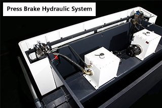
Já alguma vez se interrogou sobre o funcionamento do sistema hidráulico de uma quinadora? Neste artigo, vamos mergulhar profundamente nos meandros deste componente essencial. O nosso engenheiro mecânico especialista guiará...
Atenção a todos os mecânicos e entusiastas da engenharia! Alguma vez se interrogaram sobre os meandros da operação de uma máquina de prensagem a frio? Nesta publicação do blogue, vamos mergulhar no mundo...
A escolha entre uma prensa dobradeira eléctrica e hidráulica pode ter um impacto significativo na eficiência e nos custos da sua empresa. As prensas dobradeiras eléctricas oferecem poupanças de energia superiores, benefícios ambientais e velocidades de operação mais rápidas, enquanto...
A sua prensa dobradeira hidráulica está a causar mais dores de cabeça do que deveria? Garantir que estas máquinas complexas funcionam sem problemas é vital para evitar tempos de inatividade e reparações dispendiosas. Este artigo aborda a manutenção essencial...
Como é que uma máquina consegue uma elevada precisão e eficiência na dobragem de metais? Descubra os segredos por detrás da quinadora servo electro-hidráulica. Este artigo investiga a mecânica complexa, os procedimentos de configuração,...