Manual de operação do freio de prensa (PDF de treinamento)
Atenção a todos os mecânicos e entusiastas da engenharia! Você já se perguntou sobre os prós e contras da operação de uma máquina de prensa dobradeira? Nesta postagem do blog, vamos mergulhar no mundo dos freios de prensa, explorando suas funções, considerações de segurança e dicas de manutenção. Com base na experiência de profissionais experientes da área, forneceremos insights valiosos para aumentar sua compreensão e proficiência no uso dessas máquinas poderosas. Prepare-se para elevar o nível do seu jogo de freio de prensa!
Introdução ao manual de operação da prensa dobradeira
Recomendamos enfaticamente que todos os usuários e operadores leiam atentamente este manual de operação da prensa dobradeira antes de usar a máquina. Este manual é destinado a pessoal especializado e qualificado e vem com diagramas e toda a documentação necessária para levantar, mover e posicionar a máquina, além de instruções para uso e manutenção seguros.
Sistemas de controle disponíveis
Você pode rolar diretamente para o final da página para fazer o download da versão em PDF do manual de operação dos seguintes sistemas de controle de prensa dobradeira:
Estun: E21, E200P, E200+
CybTouch: 8, 12
Esa: S630
Delem: DA41, DA52S, DA53T, DA58T, DA66T, DA69T
Informações importantes
Observe que todas as informações contidas neste manual são precisas no momento da impressão. Entretanto, nossa empresa se reserva o direito de modificar e melhorar as especificações sem aviso prévio.
Instalação e manutenção
Para garantir o desempenho adequado, é importante instalar o freio de prensa conforme as instruções e para realizar inspeções regulares e serviços de manutenção. Qualquer uso incorreto ou irresponsável pode resultar em danos irreparáveis à máquina e comprometer a segurança do operador.
Isenção de responsabilidade
Não nos responsabilizamos por serviços, modificações ou conexões inadequadas feitas por pessoal não autorizado.
Ao seguir as diretrizes e recomendações descritas neste manual, você pode garantir a operação segura e eficiente da sua máquina de prensa dobradeira.
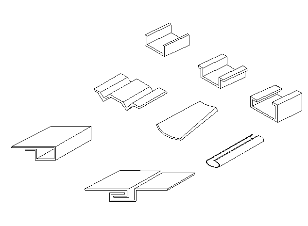
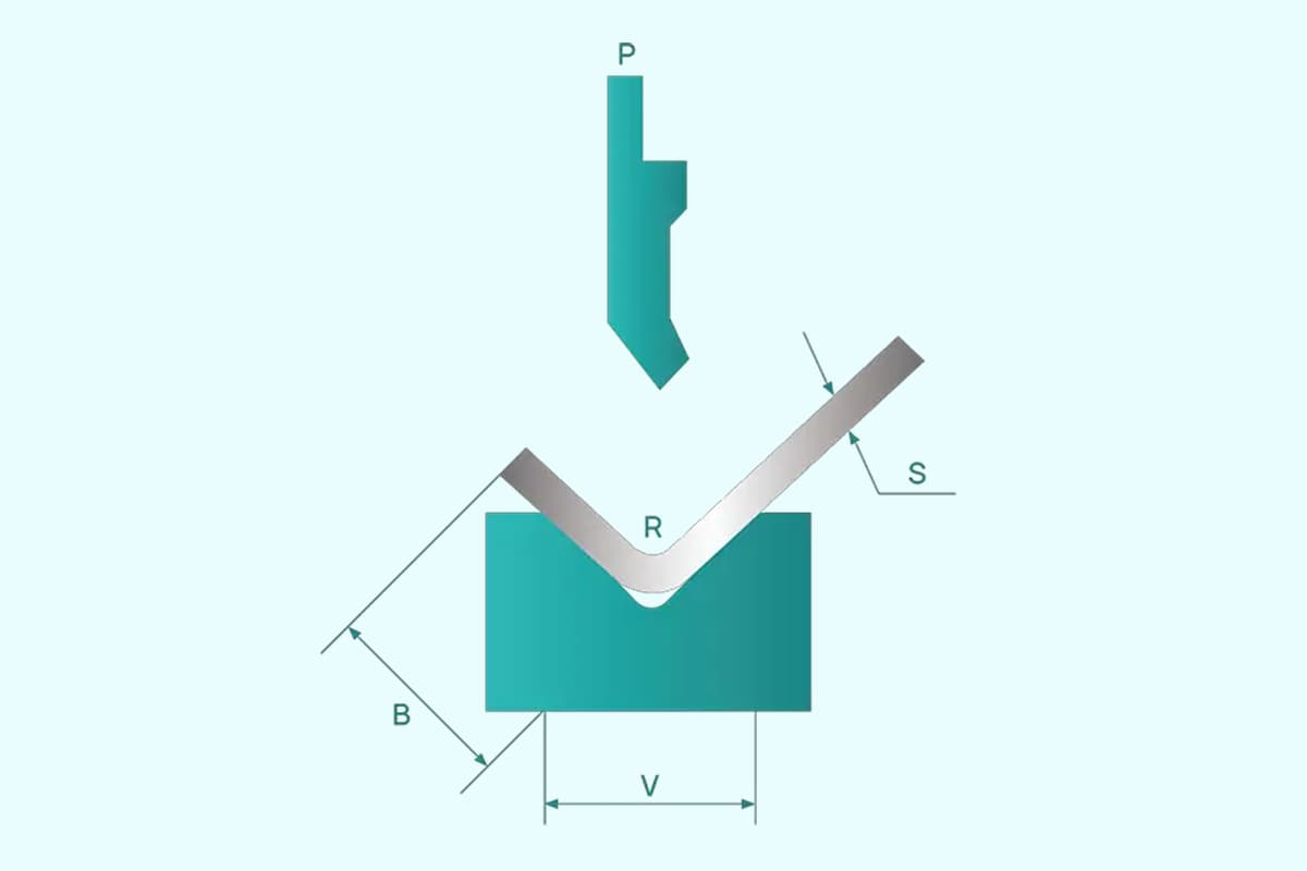
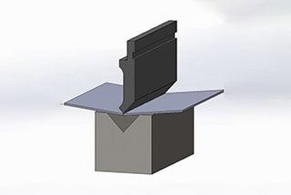
A prensa dobradeira foi projetada para proporcionar alta eficiência e precisão na dobra de chapas metálicas. O tamanho da abertura da ranhura em V nas matrizes inferiores é, normalmente, 8 vezes a espessura da chapa e deve ser ajustado de acordo com chapas de espessura variável. Diferentes tipos de matrizes superiores e inferiores podem ser usados para dobrar uma variedade de peças de trabalho, conforme ilustrado na Fig. 1.
Figura 1
1.2 Integridade estrutural e recursos de segurança
A prensa dobradeira é construída a partir da fabricação de chapas de aço, proporcionando resistência e rigidez suficientes. O sistema de acionamento hidráulico da máquina evita acidentes graves na operação de sobrecarga que podem ocorrer devido a alterações na espessura da chapa ou à seleção incorreta da cavidade inferior da matriz. Essa máquina também oferece desempenho estável, facilidade de operação e segurança confiável.
Para garantir alta precisão, a conexão com a matriz superior é equipada com um dispositivo de compensação. Esse dispositivo compensa a deflexão da mesa de trabalho e do controle deslizante durante a dobra. Além disso, o bloco mecânico é equipado com um cilindro de óleo para garantir a fixação precisa quando o controle deslizante atinge o ponto morto inferior, mantendo a consistência na produção em massa.
1.3 Controle hidráulico e elétrico
A prensa dobradeira é equipada com sistemas de controle hidráulico e elétrico, permitindo que o deslocamento do controle deslizante seja ajustado livremente. Esse recurso o torna conveniente para testes e ajustes com um critério operacional de polegadas.
1.4 Avanços tecnológicos e desempenho
Essa prensa dobradeira é tecnologicamente avançada e apresenta desempenho confiável, o que a torna um dos dispositivos de modelagem ideais. Ele é amplamente utilizado em setores como aviação, automotivo, construção naval e maquinário devido à sua alta eficiência de produção.
1.5 Condições operacionais
Temperatura: A faixa de temperatura de trabalho do freio de prensa é de 5 a 38°C.
Umidade ambiental: A umidade relativa deve estar entre 20~80% RH.
Vibração e interferência: A máquina deve ser mantida longe de vibrações fortes e interferência eletromagnética.
Condições ambientais: O ambiente operacional deve estar livre de gases perniciosos e corrosivos e de poeira.
Instalação do freio de prensa
Levantamento
Ao elevar a prensa dobradeira para transporte ou posicionamento, é fundamental usar um guindaste com capacidade de elevação suficiente para evitar o risco de queda da prensa dobradeira. Siga estas diretrizes para garantir uma elevação segura:
Use duas eslingas de cabo de aço e manilhas: Utilize os orifícios de elevação apropriados localizados na parte superior da máquina.
Cabo de aço adequado: Certifique-se de que o cabo de aço tenha o tamanho adequado para levantar o peso da prensa dobradeira. O comprimento do cabo deve ser suficiente, pois sua capacidade de carga de peso diminui quando o ângulo entre os cabos aumenta (consulte a Fig. 2).
Fig.2
Transporte
Ao transportar a prensa dobradeira, considere o seguinte:
Distribuição de peso: A maior parte do peso da prensa dobradeira está concentrada na frente. Certifique-se de que o cilindro superior esteja totalmente abaixado durante a movimentação ou o transporte.
Carregamento em um caminhão: Posicione a parte traseira da máquina o mais próximo possível da lateral do veículo. Prenda a prensa dobradeira ao caminhão usando cabos de aço para evitar qualquer movimento durante o transporte.
Instalação
Fundação da prensa dobradeira:
Para garantir a operação adequada e a estabilidade da prensa dobradeira, a superfície sobre a qual ela será colocada deve ser firme e estável. Siga estas etapas:
Fundação de concreto: Se necessário, prepare uma fundação de concreto adequada às condições específicas do solo. Consulte o desenho detalhado da fundação fornecido abaixo.
Requisitos de espaço: Certifique-se de que haja espaço adequado ao redor da máquina para trabalhos de manutenção e tarefas especiais. Deve haver espaço suficiente no lado esquerdo ou direito da prensa dobradeira, igual ao comprimento da máquina, para facilitar as operações de troca de ferramentas.
Remoção do Rust Guard: Todas as superfícies expostas da máquina são revestidas com proteção contra ferrugem, que pode ser facilmente removida com querosene ou solvente.
Nivelamento
O nivelamento adequado da prensa dobradeira é essencial para sua operação correta. Siga estas etapas para garantir que a máquina esteja nivelada:
Nivelamento horizontal: Coloque um nível de bolha de ar na mesa da máquina para verificar o nivelamento horizontal.
Nivelamento vertical: Coloque o nível de bolha de ar na mesa da máquina novamente para verificar o nivelamento vertical.
Ajustes: Faça os ajustes necessários, ajustando os parafusos de nivelamento localizados nos pés da prensa dobradeira.
Diagrama elétrico e instruções de operação da prensa dobradeira
Conexão elétrica e configuração inicial
Verifique a placa de identificação e a fiação da máquina:
Verifique os detalhes da placa de identificação da prensa dobradeira.
Verifique se toda a fiação está intacta e em boas condições.
Conexão de energia:
Conecte a prensa dobradeira à fonte de energia da instalação.
Se a energia da instalação não atender aos requisitos da máquina, entre em contato com o fornecedor de energia elétrica.
Medidas de segurança:
Certifique-se de que a energia de entrada tenha fusível para permitir a desconexão total para reparos.
Conecte a alimentação de entrada aos grampos RST no gabinete de controle.
Desenhos elétricos:
Consulte os diagramas elétricos anexos para ver as configurações específicas do controlador.
Conecte as linhas de energia trifásicas aos terminais de entrada no quadro elétrico.
Conecte o soquete do pedal localizado embaixo da caixa.
Feche o interruptor de energia QF e a porta do quadro elétrico.
O acendimento da lâmpada HL1 indica que a máquina está ligada.
Verificação da direção do motor:
Ligue o motor da bomba de óleo usando o botão HL2 no painel de operação.
Observe a direção do motor; se estiver incorreta, altere a fase das linhas de entrada (não altere as linhas internas).
Reinicie o motor da bomba de óleo.
Operação do modo Jog
Ativação do modo Jog:
Após alguns minutos de operação normal, coloque o SA2 no modo jog.
Pise no interruptor de pé "para cima"; o aríete se elevará e parará quando o interruptor for liberado.
Para elevar ainda mais o aríete, continue pisando no pedal até que ele atinja o interruptor de limite SQ1 e pare.
Para abaixar o aríete, pise "para baixo"; o aríete cairá rapidamente e depois lentamente devido ao interruptor de limite SQ2, adicionando pressão.
Solte o pedal para parar o aríete.
Modo de viagem único
Ativação do modo de viagem única:
Coloque SA2 em "single time" (tempo único).
Pressione o pedal "para baixo"; o êmbolo descerá rapidamente, depois lentamente com a pressão e, por fim, subirá até o interruptor de limite superior SQ1.
Ajuste o tempo de trabalho do relé de tempo KT1 para atender aos requisitos de pressão de flexão.
Ajuste o tempo de manutenção da pressão do relé de tempo KT2.
Modo de continuidade
Ativação do modo de continuidade:
Gire SA2 para "continuidade".
Pressione o pedal para repetir o modo de deslocamento único.
Ajuste o tempo de espera de circulação usando o relé de tempo KT1.
Nota de segurança
As etapas acima devem ser realizadas por pessoal especializado.
Por segurança, as máquinas de prensa dobradeira com certificação CE não têm um modo de continuidade.
O sistema hidráulico de uma prensa dobradeira
Limpe o óleo hidráulico
A manutenção da limpeza do óleo hidráulico é essencial para garantir o desempenho ideal e a longevidade do sistema hidráulico em uma prensa dobradeira. Aqui está um guia detalhado sobre como limpar o óleo hidráulico e o tanque de óleo:
Preparação:
Antes de começar, certifique-se de que a prensa dobradeira esteja desligada e o sistema hidráulico esteja despressurizado.
Reúna os materiais de limpeza necessários: toalhas limpas (evite usar algodão, pois ele pode deixar fibras), gasolina de limpeza e ferramentas como uma vara ou bambu enrolado em uma toalha para áreas de difícil acesso.
Remoção do óleo:
Remova cuidadosamente a tampa do tanque de óleo.
Solte o bujão de vazamento ou a válvula de freio para drenar completamente o óleo sujo do sistema.
Limpeza do tanque:
Limpe o fundo e as laterais do tanque com uma toalha limpa.
Use gasolina de limpeza para lavar bem o tanque.
Para cantos e áreas de difícil acesso, enrole uma toalha em um pedaço de pau ou bambu e limpe essas áreas meticulosamente.
Se houver sujeira acumulada nas costuras de solda ou em outros pontos difíceis, use uma ferramenta como um rolo de massa para limpar essas áreas.
Secagem do tanque:
Certifique-se de que o tanque esteja completamente seco, limpando-o com uma toalha limpa.
Recoloque a tampa do tanque quando ela estiver limpa e seca.
Escolha o óleo hidráulico
A seleção do óleo hidráulico adequado é fundamental para a operação eficiente da prensa dobradeira. Considere as seguintes diretrizes:
Viscosidade:
O valor da marca do óleo hidráulico indica sua viscosidade média a 40°C.
Para pressões e temperaturas de trabalho mais altas e velocidades de trabalho mais lentas, escolha um óleo hidráulico de grau mais alto.
Óleo recomendado:
ISO VG46: Esse óleo hidráulico antidesgaste tem uma viscosidade média de 46 mm²/s a 40°C e é adequado para a maioria das condições operacionais.
ISO VG32: Use esse óleo se a máquina operar em temperaturas abaixo de 5°C por longos períodos.
Considerações sobre a temperatura:
Evite operar a máquina em temperaturas muito baixas (abaixo de -5°C). Se necessário, deixe a máquina em marcha lenta para aquecer o óleo.
Um aquecedor de óleo pode ser adicionado ao circuito para temperaturas extremamente baixas.
Em condições normais, a temperatura do óleo não deve exceder 70°C. Instale um resfriador de óleo, se necessário, para condições especiais.
Encha o óleo
O abastecimento adequado do óleo hidráulico é essencial para manter o desempenho do sistema:
Limpeza:
Certifique-se de que o óleo utilizado esteja limpo.
Aperte a porca do filtro de ar e encha o óleo através do filtro.
Se estiver usando um equipamento de enchimento com filtro, você poderá abrir a tampa do tanque de óleo e enchê-lo diretamente.
Nível de óleo:
Observe o medidor de óleo. Quando o aríete parar no ponto morto superior, o óleo hidráulico deverá preencher cerca de 80% a 90% do espaço interno do tanque.
Remoção de bolhas de ar:
Faça a máquina funcionar primeiro em marcha lenta e depois no curso máximo para remover quaisquer bolhas de ar no circuito hidráulico.
Diagrama hidráulico
Para uma compreensão abrangente do sistema hidráulico, consulte o diagrama hidráulico fornecido. Esse diagrama ajudará na análise do sistema externo e na solução de problemas.
Equipamento de controle padrão
5.1
Botão Iniciar
Para iniciar o funcionamento do motor principal e do circuito de controle.
5.2
Botão Parar
Para interromper o funcionamento do motor principal e do circuito de controle.
5.3
Chave seletora de modo automático/manual
Selecione o modo de trabalho
No modo Auto
-O aríete se elevará automaticamente quando a pressão predefinida for atingida e o tempo de permanência terminar.
No modo Manual
-O abaixamento e a elevação do aríete são feitos pressionando o pedal.
5.4
Pedal
Pressione e mantenha pressionado para comandar a descida do aríete até atingir o ponto de flexão; solte quando o aríete estiver subindo no modo AUTO.
Pressione para comandar a descida do aríete e pressione para comandar a subida do aríete no modo Manual.
Inicialização da máquina de prensa dobradeira
Verificações antes da partida
Antes de iniciar a máquina de prensa dobradeira, é fundamental realizar várias verificações para garantir uma operação segura e eficiente:
Limpar e lubrificar as guias: Certifique-se de que as guias estejam livres de detritos e devidamente lubrificadas para facilitar o movimento suave.
Inspecionar o sistema hidráulico: Verifique se há vazamentos no sistema hidráulico. Os vazamentos podem levar a ineficiências e riscos potenciais.
Verificar o nível de óleo: Verifique o nível de óleo no medidor de nível localizado na lateral do tanque. Isso deve ser feito com o cilindro superior na posição totalmente elevada. Se necessário, complete o óleo até o nível exigido.
Direção de rotação do motor: Observe a direção do ventilador de resfriamento para garantir que o motor esteja girando corretamente. O ventilador deve girar no sentido horário ou na direção indicada pela seta. Se a rotação estiver incorreta, troque dois fios na linha de alimentação. Certifique-se de que o motor esteja funcionando por centímetros ao fazer esse ajuste.
Como ligar a máquina
Interruptor principal: Ligue o interruptor principal para alimentar a máquina.
Chave seletora: Mude o seletor para o modo "Auto".
Motor principal: Pressione o botão verde para dar partida no motor principal.
Desligamento da máquina
Quando a prensa dobradeira não estiver em uso por algumas horas, ela deve ser desligada para economizar energia e manter a segurança:
Selecione o modo manual: Coloque a máquina no modo manual.
Descer o carneiro: Pressione o pedal para baixo para abaixar o aríete, trazendo a ferramenta superior o mais próximo possível da matriz em V.
Botão Parar: Pressione o botão de parada para parar a máquina.
Interruptor principal: Desligue o interruptor principal para desligar completamente a máquina.
O alinhamento adequado das ferramentas superior e inferior é essencial para operações de dobra precisas:
Desenhos de ferramentas: Consulte os desenhos das ferramentas do freio de prensa para obter orientação.
Superfícies limpas: Certifique-se de que a base do V-die e as superfícies da mesa estejam limpas para evitar qualquer desalinhamento ou dano.
Pressão mais baixa do sistema: Gire o botão regulador de pressão no sentido anti-horário para diminuir a pressão do sistema.
Ajuste do limitador de profundidade mecânico: Ajuste o limitador de profundidade mecânico para a posição mais baixa, manual ou eletricamente.
Modo manual: Selecione o modo manual e pressione o pedal para baixo para abaixar o aríete até que a ferramenta superior esteja o mais próximo possível da matriz em V.
Ferramentas de alinhamento: Ajuste os parafusos de aperto da matriz em V para alinhar as ferramentas superior e inferior com precisão.
Aperte os parafusos: Quando o alinhamento estiver correto, aperte com firmeza todos os parafusos de aperto do V-die.
Levantar o carneiro: Pressione o pedal UP para elevar o aríete.
Recomendações adicionais
Verificações regulares dos parafusos: Verifique regularmente os parafusos de fixação do grampo da ferramenta para garantir que estejam seguros.
Armazenamento de ferramentas: Armazene as ferramentas em um suporte próximo à prensa dobradeira para evitar danos à ferramenta superior.
Capacidade da ferramenta: Esteja ciente da capacidade máxima de força de cada ferramenta para evitar sobrecarga e possíveis danos.
Procedimento de troca de ferramentas para prensa dobradeira
Procedimento de troca da ferramenta superior
Mudar para o modo manual: Gire o seletor de modo para manual.
Abaixe o carneiro: Abaixe o carneiro o mais próximo possível da matriz em V.
Desligado: Desligue a máquina.
Solte o grampo da ferramenta: Solte todos os parafusos de fixação do grampo da ferramenta.
Remover a ferramenta: Remova a ferramenta superior da lateral da máquina.
Montar nova ferramenta: Deslize a nova ferramenta superior pelo mesmo lado.
Aperte o grampo da ferramenta: Aperte todos os parafusos de fixação do grampo da ferramenta.
Ligar: Ligue a máquina e verifique se o seletor de modo está em manual.
Assentar a ferramenta superior: Abaixe o êmbolo para assentar a ferramenta superior na matriz em V e, ao mesmo tempo, reduza a pressão do sistema girando o botão regulador de pressão no sentido anti-horário para evitar danos à ferramenta.
Procedimento de troca da ferramenta inferior
Desaparafusar os parafusos de aperto: Desparafuse todos os parafusos de aperto para liberar o V-die.
Mudar para o modo manual: Mude o seletor de modo para manual.
Ligar: Ligue a máquina.
Abaixe o carneiro: Abaixe o carneiro o mais próximo possível da matriz em V.
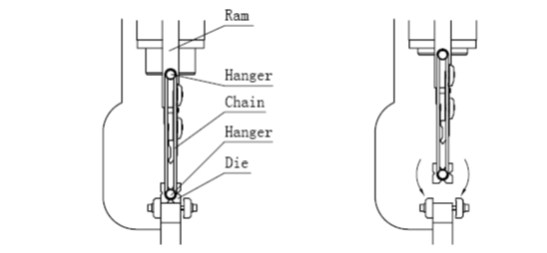
Enganchar o molde em V: Prenda a matriz em V no cilindro em ambas as extremidades usando as correntes apropriadas.
Levantar o carneiro: Eleve o aríete pisando no pedal UP até uma altura em que o V-die possa girar.
Girar o molde em V: Vire a matriz em V desejada para cima.
Abaixe o carneiro: Abaixe o aríete pisando no pedal DOWN de modo que a matriz fique apoiada na mesa da máquina e as correntes possam ser desengatadas.
Centralizar o molde em V: Centralize a matriz em V com relação à ferramenta superior.
Travar a matriz em V: Trave o V-die no lugar apertando os parafusos.
Ajuste do braço de suporte frontal
A prensa dobradeira vem de fábrica com dois braços de suporte frontais. Esses braços de suporte são usados para manter a chapa no lugar durante o processo de dobra. Eles podem ser ajustados verticalmente e ao longo do comprimento da prensa dobradeira. Os braços de suporte geralmente precisam ser ajustados quando se usa uma ferramenta inferior de tamanho diferente ou quando se dobra uma chapa de tamanho maior ou menor.
Precauções de segurança
PERIGOSO!
Se o punção e a matriz não estiverem posicionados corretamente, não dê partida na máquina em nenhum momento.
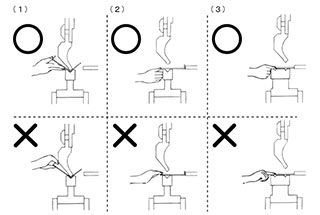
Não insira as mãos ou qualquer parte do corpo no espaço entre o punção e a matriz, pois isso é extremamente perigoso.
Ajuste mecânico do limitador de profundidade
Ao trabalhar com uma prensa dobradeira, é fundamental lidar com a configuração do limitador de profundidade mecânico com cuidado para evitar possíveis danos à máquina. Aqui estão alguns pontos importantes a serem considerados:
Evite ajustes com o Ram Down: Nunca tente ajustar a configuração do limitador de profundidade mecânico quando o êmbolo estiver na posição para baixo. Isso pode causar danos desnecessários à máquina devido à pressão e ao posicionamento dos componentes.
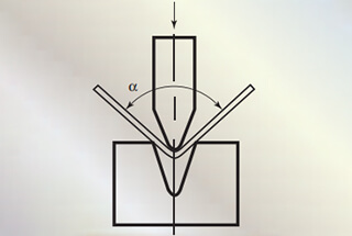
Determina o ângulo de flexão: A configuração de profundidade é essencial, pois determina o ângulo de dobra da chapa metálica. Ajustes precisos de profundidade garantem dobras precisas e produtos acabados de alta qualidade.
Configurações manuais ou elétricas: O limitador de profundidade mecânico pode ser ajustado manual ou eletricamente, dependendo do projeto e das capacidades da prensa dobradeira. Os ajustes manuais normalmente envolvem a manipulação física do batente, enquanto os ajustes elétricos podem ser controlados por meio de uma interface de usuário ou painel de controle.
Ajuste de pressão
A configuração da pressão em uma prensa dobradeira é vital para obter a dobra desejada sem danificar o material ou a máquina. Aqui estão os fatores e as considerações para definir a pressão de dobra:
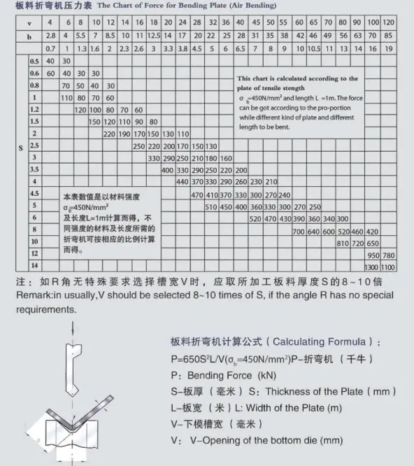
Gráfico de flexão: Normalmente, uma tabela de flexão é fixada na lateral da máquina e uma cópia costuma ser anexada à documentação da máquina. Essa tabela fornece informações essenciais para definir a força de flexão correta.
Fatores que afetam a força de flexão:
Espessura da placa: A espessura da placa influencia diretamente a força de flexão necessária.
Largura da abertura da matriz: A largura da abertura da matriz, geralmente calculada como 8 vezes a espessura da chapa, também afeta a força de flexão.
Cálculo da força de flexão: A força de flexão necessária pode ser calculada usando uma fórmula fornecida na Tabela 1. Essa fórmula e os valores da tabela são baseados em placas de aço carbono com resistência à tração de Qb=450KN.
Para placas de aço inoxidávelmultiplique o valor P da tabela por 2.
Para placas de alumíniomultiplique o valor P da tabela por 0,7.
Calculadora de tonelagem: Para obter cálculos mais precisos, você pode usar uma calculadora de tonelagem especialmente projetada para prensas dobradeiras. Essa ferramenta ajuda a determinar a força exata necessária com base no material e nos parâmetros de dobra.
Controle e ajuste de paralelismo para o carneiro da prensa dobradeira
Garantir o paralelismo do aríete em uma prensa dobradeira é fundamental para obter curvas precisas e consistentes em chapas metálicas. Normalmente, o paralelismo é controlado por uma barra anti-torção sólida ligada aos dois cilindros de óleo laterais. Aqui está um guia detalhado sobre como controlar e definir o paralelismo do aríete:
Calibração de fábrica
O aríete superior da prensa dobradeira é calibrado paralelamente à matriz em V na fábrica. Entretanto, com o tempo e o uso, pode ser necessário recalibrar para manter a precisão.
Etapas para recalibração
Localize a articulação da barra de torção:
Localize a articulação da barra de torção conectada ao cilindro superior na parte traseira (lado esquerdo) da máquina.
Solte o parafuso:
Identifique o parafuso (M8/M10) na barra de torção.
Solte esse parafuso para permitir o ajuste.
Ajuste da barra de torção:
Use as chaves apropriadas para girar a peça plana externa em 15° a 30°.
Você pode girá-lo no sentido horário ou anti-horário, o que girará o pino excêntrico interno.
Aperte o parafuso:
Depois de fazer o ajuste, aperte o parafuso (M8/M10) com firmeza.
Verificar paralelismo:
Faça uma dobra de teste para verificar o paralelismo do cilindro superior.
Se o aríete ainda não estiver paralelo, repita o processo de ajuste.
Repetir se necessário:
Continue o procedimento até atingir a precisão desejada.
Dicas para um ajuste preciso
Use ferramentas de precisão: Certifique-se de que esteja usando ferramentas calibradas para medição e ajuste para manter a alta precisão.
Realizar várias curvas de teste: Pode ser necessário fazer várias dobras de teste para obter o paralelismo perfeito. Seja paciente e faça pequenos ajustes.
Ajustes de documentos: Mantenha um registro dos ajustes feitos para referência e manutenção futuras.
Solução de problemas do freio de prensa
A máquina de prensa dobradeira não consegue iniciar
Verificar a fonte de alimentação de entrada: Certifique-se de que a máquina esteja recebendo a tensão e a corrente corretas, conforme especificado pelo fabricante. Verifique se todas as conexões estão seguras e se não há problemas com a fonte de alimentação.
Verifique se a parada de emergência está liberada: Confirme se o botão de parada de emergência não está acionado. Se estiver, solte-o e reinicie a máquina.
Verifique se há fusíveis quebrados: Inspecione a continuidade de todos os fusíveis no painel elétrico. Substitua os fusíveis queimados por outros com a classificação correta.
Verificar a saída do transformador: Verifique se o transformador está emitindo a tensão correta. Se a saída estiver incorreta, talvez seja necessário substituir o transformador.
Não foi possível abaixar o carneiro
Verifique o cabo do pedal para ver se há algum fio quebrado: Inspecione o cabo do pedal para verificar se há sinais de danos ou fios quebrados. Substitua o cabo se encontrar algum problema.
Verifique o interruptor de limite: Verifique se o interruptor de limite está funcionando corretamente. Teste a chave com um multímetro para verificar seu funcionamento. Substitua se estiver com defeito.
Verificar a rotação do motor: Confirme se o motor está girando na direção correta. A rotação incorreta do motor pode impedir a descida do aríete. Ajuste a fiação, se necessário.
Verifique o microinterruptor dentro do pedal: Verifique se o microinterruptor dentro do pedal está funcionando. Teste-o com um multímetro e substitua-o se ele não estiver funcionando corretamente.
Ângulo de dobra não uniforme em todo o comprimento da dobra
Ferramenta superior ou inferior desgastada: Inspecione as ferramentas superiores e inferiores quanto a desgaste. Substitua as ferramentas desgastadas para garantir ângulos de dobra consistentes.
A superfície da mesa da máquina e a parte inferior do V-Die estão sujas: Limpe a superfície da mesa da máquina e a parte inferior da matriz em V. A sujeira e os detritos podem afetar a precisão da dobra.
Ferramentas superior e inferior não alinhadas corretamente: Verifique o alinhamento das ferramentas superior e inferior. O desalinhamento pode causar ângulos de dobra irregulares. Ajuste as ferramentas para garantir que estejam alinhadas corretamente.
Falha
Motivos
Remoção de problemas
O sistema não funciona sem pressão
1. Rotação negativa do motor
Alterar o sentido de rotação do motor
2. Válvula de transbordamento principal bloqueada
Limpe a válvula de transbordamento principal
3. A válvula eletromagnética não funciona
Verifique as bobinas elétricas e eletromagnéticas
O Ram Slider não consegue se elevar
Válvulas emperradas
Limpe as válvulas eletromagnéticas
O controle deslizante diminui automaticamente
Válvulas emperradas
Limpe as válvulas eletromagnéticas
Subida e descida normais, mas não há força na flexão
Válvulas emperradas
Limpe a válvula eletromagnética
Vazamento em componentes, conexões de tubulação e cilindro de óleo
As peças de vedação estão envelhecendo.
Trocar os anéis de vedação
Manutenção do freio de prensa
Diretrizes gerais
Leia o manual: Certifique-se de que todas as pessoas que operam ou fazem a manutenção da prensa dobradeira leiam e entendam completamente o manual. O cumprimento rigoroso das instruções é essencial para a obtenção de resultados ideais.
Operador designado: Designe uma pessoa para operar a máquina. Os operadores devem ter um conhecimento prático da operação da máquina e dos protocolos de segurança.
Força de flexão e distribuição de carga
Força nominal: A força de flexão aplicada à peça de trabalho não deve exceder a força nominal da prensa dobradeira.
Vida útil do molde: Para prolongar a vida útil dos moldes, evite danificá-los devido a uma largura de dobra inadequada, especialmente ao dobrar chapas estreitas. Nesses casos, reduza adequadamente a pressão de trabalho.
Carga de flexão: Para cada 630 mm de comprimento, a carga de flexão não deve exceder 400KN.
Centralização de carga: Certifique-se de que as chapas que estão sendo dobradas estejam centralizadas na máquina para manter a precisão. O carregamento irregular pode comprometer as peças de trabalho e a máquina.
Dobramento lateral: Se uma peça de trabalho precisar ser dobrada apenas em um lado, a carga não deve exceder um quarto da força nominal. Realize a flexão em ambos os lados para equilibrar a carga.
Manutenção do sistema hidráulico
Cronograma de troca de óleo:
Troque o óleo hidráulico após o primeiro mês de uso.
Posteriormente, troque o óleo a cada 2.000 horas de trabalho.
Temperatura do óleo: Mantenha a temperatura do óleo entre 15 e 60°C. Se a temperatura exceder essa faixa, instale um resfriador.
Tipo de óleo: Use óleo hidráulico antidesgaste ISO VG46# (viscosidade média de 46 mm²/s a 40°C). Para operações abaixo de 5°C, use ISO VG32#.
Nível e qualidade do óleo:
Verifique regularmente o nível de óleo no tanque.
Use óleo que atenda às características especificadas.
O valor de marca do óleo hidráulico corresponde à viscosidade média a 40 °C.
Filtro de óleo:
Limpe regularmente o filtro de óleo enxaguando-o e escovando-o com um solvente.
Substitua o filtro de óleo quando não for possível limpá-lo ou se ele estiver danificado.
Use o mesmo tipo de filtro de óleo quando a substituição for necessária.
Lubrificação
Pontos de lubrificação:
Verifique regularmente os pontos de lubrificação.
Lubrifique semanalmente com graxa de alta qualidade.
Para peças expostas ao desgaste sem pontos de lubrificação, lubrifique duas vezes por semana.
Diagrama de lubrificação: Consulte o diagrama de lubrificação para obter detalhes específicos sobre os pontos de lubrificação.
Manutenção elétrica
Terminais elétricos:
Inspecione regularmente todas as conexões no painel principal e nos interruptores elétricos.
Aperte os parafusos conforme necessário.
Substitua todos os fusíveis e luzes de sinalização com defeito.
Inspeção de peças mecânicas
Cheques mensais:
Certifique-se de que o rolamento da barra de torção esteja devidamente fixado.
Verifique se as lâminas não estão desgastadas.
Verifique se as hastes do cilindro estão devidamente fixadas.
Certifique-se de que o cilindro superior esteja devidamente preso.
Acessórios de manutenção
Disponibilidade: Mantenha os acessórios de manutenção sempre à mão.
Precisão pós-reparo: Após qualquer reparo pesado, verifique se a precisão da máquina atende aos padrões de fábrica.
Condições especiais
Operação em baixa temperatura: Evite usar a máquina em temperaturas muito baixas (abaixo de -5°C). Se necessário, deixe a máquina funcionar em marcha lenta por algum tempo. Um aquecedor de óleo pode ser instalado, se necessário.
Operação em alta temperatura: Em condições normais, a temperatura do óleo não deve exceder 70°C. Um resfriador de óleo pode ser necessário em condições especiais.
Óleos hidráulicos recomendados
FIAT-HTF 46
ENERGOL HLP 46
ESSO NUTO H46
SHELL-TELLUS S46
TOTAL-AZOLLA 46
Garantia de segurança e construção principal da máquina de prensa dobradeira
Introdução
Esta seção fornece diretrizes para garantir a segurança do pessoal e do equipamento ao operar uma máquina de prensa dobradeira. Embora seja adaptada a requisitos específicos, ela também pode servir de referência para outras máquinas.
Equipamento de segurança
Para garantir a segurança do pessoal e do equipamento, vários mecanismos de segurança foram integrados à máquina de prensa dobradeira. Os operadores não devem alterar, remover ou desativar nenhum equipamento de segurança.
Feixe de luz/feixe de laser
A máquina pode ser equipada com um feixe de luz ou de laser, dependendo das necessidades do cliente. Esses feixes formam uma cortina de luz que, quando sofre interferência, ativa o módulo de segurança. Isso impede que o aríete se mova para baixo, protegendo assim o operador de possíveis lesões.
Grade de segurança
Uma grade de segurança é instalada na lateral e na parte traseira da máquina para manter os operadores longe de áreas perigosas. Essa grade é conectada ao sistema elétrico por meio de um interruptor de segurança. Quando a grade de segurança é aberta, o sistema elétrico é ativado, tornando a máquina inoperante.
Parada de emergência
Os botões de parada de emergência estão estrategicamente localizados na estação de controle da alça e na estação de controle de suspensão. No caso de um erro operacional ou de qualquer outro acidente, pressionar o botão de parada de emergência interromperá imediatamente todas as ações da máquina.
Sistema hidráulico
O sistema hidráulico é um componente essencial da máquina de prensa dobradeira. A queda do cilindro representa um perigo significativo, que é atenuado pela inclusão de uma válvula de elevação de segurança. Os núcleos das válvulas, tanto da válvula de troca quanto da válvula de elevação de segurança, são monitorados. Se for detectada alguma anormalidade nos núcleos da válvula, o sinal de monitoramento interromperá o sistema elétrico para evitar ferimentos causados pela queda do êmbolo. Se os núcleos da válvula não puderem ser redefinidos, a válvula deverá ser inspecionada imediatamente.
Solução de problemas
A operação normal da máquina de prensa dobradeira é segura quando todos os protocolos de segurança são seguidos. Entretanto, no caso de acidentes incomuns ou durante a manutenção e o reparo, as seguintes medidas devem ser tomadas:
Trave a grade de segurança.
Aperte o botão de parada de emergência localizado dentro dos montantes.
Procure ajuda profissional.
Se alguma parte do corpo ficar presa pelo punção ou pela chapa, siga estas etapas:
Pressione o botão de parada de emergência.
Inspecione a situação cuidadosamente.
Reinicie a máquina somente depois de se certificar de que é seguro fazê-lo.
Mude o modo de operação para a posição "inch" (polegadas).
Pressione o botão de retorno da alça para retrair o êmbolo e liberar as peças presas.
Como fundador do MachineMFG, dediquei mais de uma década de minha carreira ao setor de metalurgia. Minha vasta experiência permitiu que eu me tornasse um especialista nas áreas de fabricação de chapas metálicas, usinagem, engenharia mecânica e máquinas-ferramentas para metais. Estou sempre pensando, lendo e escrevendo sobre esses assuntos, esforçando-me constantemente para permanecer na vanguarda do meu campo. Permita que meu conhecimento e experiência sejam um trunfo para sua empresa.
Atenção a todos os entusiastas da metalurgia! Está cansado de adivinhar a tonelagem adequada para a sua prensa dobradeira? Não precisa mais procurar! Nesta postagem do blog, vamos nos aprofundar no mundo da prensa...
Os operadores de prensa dobradeira desempenham um papel crucial na formação do mundo ao nosso redor, mas seu trabalho não é isento de riscos. Neste artigo, exploraremos dicas essenciais de segurança do setor...
Suas ferramentas de prensa dobradeira estão se desgastando muito rapidamente? Este artigo aborda as técnicas essenciais de reparo para prolongar a vida útil de suas ferramentas, garantindo o desempenho ideal de suas chapas metálicas...
Você já se perguntou sobre as origens do termo "freio de prensa"? Nesta cativante postagem do blog, embarcaremos em uma fascinante jornada pela história para descobrir as razões por trás...
Você já se perguntou como as chapas de metal são habilmente dobradas em formas complexas? Este artigo explora seis tipos de processos de dobragem de prensa dobradeira - dobragem, limpeza, dobragem a ar, embutimento, cunhagem e dobragem de três pontos. Você verá...
No vasto mundo da manufatura, uma máquina se destaca: a prensa dobradeira. Com sua capacidade de dobrar e moldar metal com precisão e potência, ela se tornou uma máquina indispensável...
Você já se perguntou o que mantém uma prensa dobradeira CNC funcionando sem problemas? A resposta está no óleo hidráulico. Esse fluido essencial garante o desempenho ideal e a longevidade da máquina. Nosso artigo...
O reparo adequado do cilindro hidráulico de uma prensa dobradeira é fundamental para manter o desempenho e a segurança da máquina. Normalmente, o cilindro hidráulico consiste em um pistão, uma luva, uma haste de pistão e um parafuso....
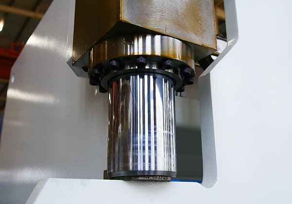
Você já se perguntou como uma prensa dobradeira consegue fazer curvas tão precisas? Este artigo explora o fascinante mundo dos eixos da prensa dobradeira, revelando os segredos por trás de seus papéis e funções. Saiba como...