Have you ever wondered how to safely and efficiently operate a punch machine? This article delves into essential procedures for running punch machines in manufacturing. It covers safety guidelines, preparation steps, and detailed operational methods to ensure high-quality output and equipment longevity. Whether you’re a novice or an experienced operator, you’ll find valuable insights to enhance your understanding and skills in punch machine operation.

To standardize the safe operation of stamping and forming processes in the petrochemical product manufacturing process, ensure the quality of processed products, and prolong the service life of equipment, this operating instruction has been formulated. It must be strictly followed by the ordinary punch operators of the company.
This applies to the operational guidance for blanking, punching, and forming of low-carbon steel, low-alloy steel, and stainless steel plates in the stamping and forming processes of the petrochemical product manufacturing industry.
None
4.1 Operators of ordinary punching machines in the production workshop must strictly observe the safety operating procedures and wear the required labor protection articles.
4.2 The Technology Department should prepare production drawings and process cards according to the production plan. They should also supervise and inspect the implementation of the punch operation instructions and process disciplines, and publish them in a timely manner.
4.3 The operator should carry out operations, self-inspection, quality assurance, equipment maintenance, and report filling according to the process card.
4.4 The inspectors in the Quality Control Department are responsible for the first article confirmation, patrol inspection, quality inspection of process products, and supervision of the implementation of process parameters.
4.5 The production workshop is responsible for the production plan decomposition and progress tracking.
5.1.1 The stamping process is a method of processing workpieces with a specific size, shape, and performance by applying external force to the blank through the mold to cause plastic deformation or separation.
Stamping technology has a wide range of applications and can be used to process metal sheets, bars, and various non-metallic materials. Because the process is typically carried out at room temperature, it is also referred to as cold stamping.
5.1.2 Features of the stamping process:
1)It can produce workpieces with complex shapes that are difficult to obtain using other processing methods. For instance, thin shell parts can be obtained by cold stamping processing. The dimensional accuracy of cold stamping parts is guaranteed by the die, resulting in stable dimensions and good interchangeability.
2)Stamping has a high material utilization rate, resulting in lightweight, rigid, and strong parts with low energy consumption during the stamping process. Consequently, the cost of the workpiece is low.
3)This operation is simple and has low labor intensity. It is also easy to realize mechanization and automation, which leads to high productivity.
4)The die structure used in stamping processing is generally complex, which results in a long production cycle and high cost.
5.1.3 Basic Requirements for Stamping Materials
1)The materials used for stamping must not only meet the technical requirements of the product design but also meet the requirements of the stamping process and processing requirements after stamping, such as cutting, electroplating, and welding.
2)Requirements for material properties of stamping forming:
a. For the forming process, to facilitate the stamping deformation and improve the quality of the parts, the materials should have good plasticity (uniform elongation δb height), a small yield ratio (σs/ σb), a large plate thickness directivity coefficient, a small plate plane directivity coefficient, and a small ratio of material yield strength to elastic modulus (σS/E).
b. For the separation process, the material does not need to have excellent plasticity, but it should have a certain level of plasticity. The harder it is to separate, the better the plasticity should be.
3)Requirements for material thickness tolerance:
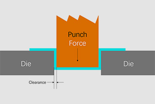
The material’s thickness tolerance must comply with national standards. If the material’s thickness tolerance is too large, it can directly affect the quality of the parts and may also cause damage to the die and punch. This is because a certain die clearance is suitable for a specific thickness of the material.
4)Requirements for material surface quality:
a. The material surface must be smooth and flat, free of delamination, mechanical property damage, rust spots, oxide skin, and any other attachments.
b. Materials with good surface quality are less likely to crack or scratch the mold during stamping. This results in high-quality workpiece surface quality.
5.2.1 Fracture separation process:
The fracture separation process is used to separate stamped parts from sheet metal along a specific contour line during the stamping process. This process can be accomplished through various techniques, such as blanking, punching, trimming, cutting, sectioning, and more.
1) Blanking:
Blanking is the process of cutting a flat plate along a closed contour, and the remaining material is considered scrap. This method is commonly used as the initial step in shaping a workpiece, as shown in Figure 1.

Fig. 1 Schematic Diagram of Blanking
2) Punching:
“Punching” refers to the process of creating holes of various shapes using blanking parts or other shaped parts (see Fig. 2). This process can include both punching and blanking.

Fig. 2 Punching Diagram
3) Trimming:
Trimming involves removing excess material from the edge of the formed part to achieve the desired shape and size of the workpiece (refer to Fig. 3).

Fig. 3 Schematic Diagram of Trimming
4) Notching:
As depicted in Figure 4, the local material is cut and bent at a specific angle on the material without being entirely separated from the main body. This process is commonly known as notch or punch forming.
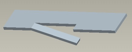
Fig. 4 Schematic Diagram of Notch
5) Sectioning:
The process of creating a solid shape in Fig. 5 involves dividing the piece into two sections, which is called sectioning.
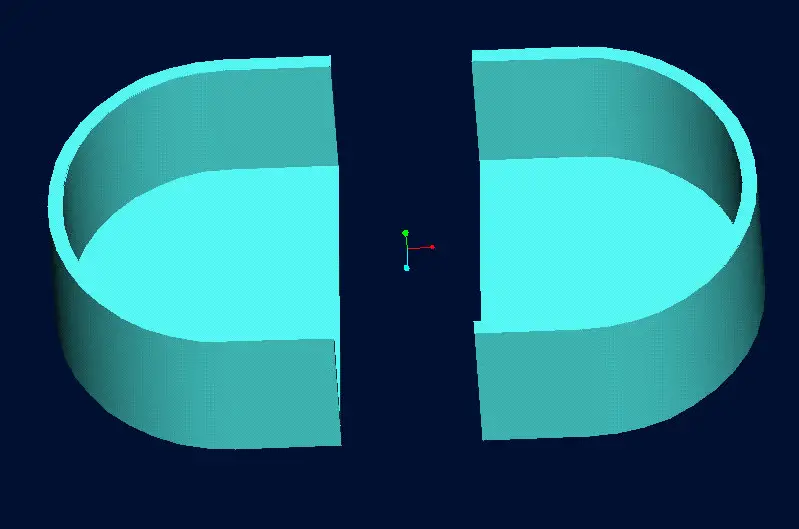
Fig. 5 Sectioning Diagram
5.2.2 Plastic forming process:
Plastic forming processes involve reshaping materials without causing them to crack, in order to create parts with specific shapes, sizes, and accuracy requirements. Examples of plastic forming processes include bending, deep drawing, bulging, flanging, necking, and crimping.
1) Bending:
The diagram in Figure 6 illustrates the process of bending a plate blank to a specific angle or further shaping the bent section through techniques such as bending, curling, twisting, and so on.

Fig. 6 Bending Diagram
2) Stretching:
As depicted in Figure 7, the flat blank undergoes a rolling process to form a hollow piece, or the hollow blank is subjected to additional deformation.
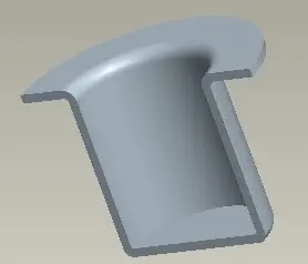
Fig. 7 Stretching Diagram
3) Bulging:
As depicted in Figure 8, the hollow piece is subjected to radial pressure from the inside to increase its local diameter. This technique is commonly employed in the manufacture of stainless steel teapots, cups, and other similar products.
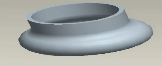
Fig. 8 Bulging Diagram
4) Necking:
As depicted in Figure 9, to decrease the local diameter of hollow objects such as stainless steel cup covers, tank products, etc., apply pressure to the exterior.
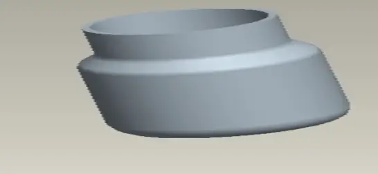
Fig. 9 Schematic Diagram of Necking
5) Rolling:
As illustrated in Figure 10, utilize a rolling die to curve the edge of the hollow object outward into an arc shape. This method is commonly employed for can products.
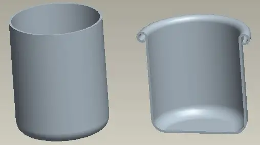
Fig. 10 Schematic Diagram of Rolling Circle
(1) Prepare for the operation by checking equipment, molds, and fixtures.
(2) Select materials, tools, and measuring tools according to the manufacturing order (MO).
(3) Calibrate tools and measuring equipment and conduct self-inspection of materials.
(4) Commission the equipment.
(5) Begin processing operations and perform first inspection.
(6) Submit for inspection.
(7) At the end of the operation, reset the operating handle and shut down the system.
5.4.1 Operation preparation:
1)Clean the surrounding area of the press to ensure it is tidy for normal operation.
2)Check the lubrication of all parts and ensure that all lubrication points are fully lubricated.
3)Verify the correct and reliable installation of the mold, and ensure there are no debris inside to prevent product damage and mold damage.
4)Ensure the power switch of the feeder is turned on to prevent dislocation due to non-feeding.
5)Disconnect the flywheel from the clutch to start the motor.
6)When starting the motor, ensure that the flywheel’s rotation direction matches the rotation sign. If not, immediately cut off the power supply for inspection and adjust the power supply sequence.
7)Move the press several times, check the operation of the brake, clutch, and horse operator, and begin normal operation after verifying that the punch is functioning properly.
5.4.2 Operation method
1)Follow the startup method outlined in the Punch Operation Manual to initiate the punching process. Turn on the blow pipe switch to prevent the product from being blown away, which could result in stacking and damage.
2)Manually test punch several workpieces for self-inspection purposes. Full-time inspectors must confirm normal operation before proceeding.
3)During normal continuous stamping, hold the red brake button with one hand, sit upright, and concentrate on the mold and outlet. Avoid talking or joking with others to prevent damage to the mold or disqualification due to misplacement or punches dropping. Check the punched product’s appearance, size, pressing, small holes, deformation, burrs, oil stains, and main dimensions’ conformity every 5-10 minutes.
4)Record detailed information on the Personal Production Daily Report during normal stamping, including the production quantity of each roll or hour. Stamping personnel should fill in the required fields accurately.
5)If any abnormality is found in the machine tool products during normal stamping, it is essential to stop the machine immediately and report it to the superior for timely treatment. Moreover, one should also assist the quality inspector in distinguishing and isolating the defective products.
6)After punching, the working area environment should be sorted out, including empty boxes, finished boxes, and stools. The punch and blow pipe should be closed in the correct order, and all power switches and oil duct switches should be turned off before leaving the work post.
7)If molds, punches, and feeders need adjustment or repair during operation, the first product produced after the correction should be submitted to the full-time inspector for confirmation. Furthermore, the First Piece List should be issued before continuing production.
8)If abnormal shutdown occurs during normal stamping production due to power failure, insufficient air pressure, etc., parts produced during that time must be scrapped. If re-production is required, it must be inspected by the Quality Department before continuing production.
9)Regularly add lubricating oil to each lubricating point and oil the inner and outer guide pillars of the mold every four hours.
5.5.1 The outer panel requires high standards with no visible defects allowed.
5.5.2 The inner plate must be free of cracks, including hidden ones.
When inspecting deep drawing parts, start by checking the pressure points for clarity. Next, look for any hidden cracks. Finally, touch and push the parts with an oilstone.
1) Bumpy
a. Method of evaluation: Use your hands to touch, push with an oilstone, and visually inspect.
It is recommended to use the oilstone pushing method. Bulges should be highlighted, while depressions should appear as dark spots.
b. Cause: If there is unevenness, check whether there is any sand or other foreign matter in the mold.
c. Treatment: If there is sand, wipe the mold with mold wiping paper.
2) Cracking (concealed cracking)
a. Judgment method: Use eyes to check the corners of the drawing parts and other places with large material deformation, and turn over the reverse side to check.
b. Cause: It may be that the die is strained and the blank holder force is too large.
c. Treatment method: check whether the workpiece is seriously strained, and properly reduce the side force.
3) Wrinkle
a. Judgment method: look with eyes;
b. Cause: small blank holder force;
c. Treatment: appropriately increase the blank holder force.
4) Burrs
a. Judgment method: Look with your eyes.
b. Cause: The clearance between male and female dies is large.
c. Treatment method: mold repair.
5) Hole deflection
a. Judgment method: check with upper inspection tool and compare with the sample.
b. Cause: The workpiece is not placed properly, and the mold positioning device is faulty.
c. Treatment method: If the hole is still deviated after the workpiece is straightened, report to the shift leader and notify mold repair.
6) Pinhole
a. Judgment method: compare with the sample.
b. Cause: The punch is broken.
c. Treatment: stop production immediately, report to the shift leader immediately, and notify mold repair.
7) Hole deformation
a. Judgment method: Look with your eyes.
b. Cause: The punch is worn.
c. Treatment method: report to the shift leader and notify mold repair if slight oiling and severe oiling still have deformation.
8) The drawing is not in place.
a. Judgment method: check whether the pressure point is clear.
b. Cause: The main pressure is too low.
c. Treatment: appropriately increase the main pressure.
9) Poor folding
a. Judgment method: compare with the sample
b. Cause: The parts are not placed properly, and the positioning device is faulty.
c. Handling method: place the workpiece properly. If it is still defective, report to the shift leader and notify the mold repair personnel to repair the mold.
10) Imprint
a. Judgment method: Look with your eyes.
b. Cause: There are granular impurities on the working surface of the upper mold.
c. Treatment: Wipe the upper mold clean.
11) Strain
a. Judgment method: Look with your eyes.
b. Cause: The working face of the die is worn and the hardness of the die is not enough.
c. Treatment method: mold repair.
12) Sand grain
a. Judgment method: push with an oilstone.
b. Cause: The material or mold surface is not clean.
c. Treatment: check the materials or wipe the mold surface clean.
13) Bump and scratch
a. Judgment method: Look with your eyes.
b. Cause: The incoming or outgoing materials touch hard objects such as molds.
c. Treatment: Be careful when feeding and discharging materials, handle the products with care, and increase the closing height of the mold if necessary.
6.1.1 When it takes more than 10 minutes to leave the machine, be sure to turn off the power to save electricity.
6.1.2 Oily rags or cotton yarn during operation and machine maintenance must be placed in the designated recycling place.
6.1.3 The waste produced during operation must be placed in the designated waste area, and it is strictly prohibited to throw it anywhere.
6.1.4 Oil used for operation and machine maintenance must be placed separately and recycled uniformly.
6.2.1 Non electricians are not allowed to open the distribution box and touch the circuit without permission to avoid electric shock.
6.2.2 It is forbidden to smoke around oil and gas storage tanks to prevent fire or explosion.
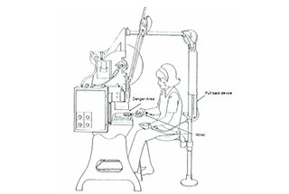
6.2.3 During the operation of the machine, the motor belt must be equipped with a protective cover. The safety protection device cannot be removed arbitrarily.
6.2.4 Press the start button with both hands to prevent industrial accidents.
6.2.5 The stamping operation shall be highly concentrated to ensure that the products and molds are normal.
6.2.6 During the operation of the punch, it is forbidden to put your hand into the mold or beside it to ensure your health and safety.
6.2.7 During normal stamping, it is strictly forbidden to work with two or three people on the same machine.
Pay special attention to the self inspection action of taking products and the action of picking up products in the receiving chute to ensure personal safety.
6.2.8 The equipment shall be stopped immediately if it is found abnormal.
6.2.9 Disconnect the flywheel from the clutch and turn off the power after work.
6.2.10 Wipe and clean the press and apply oil on the unpainted machined surface.

