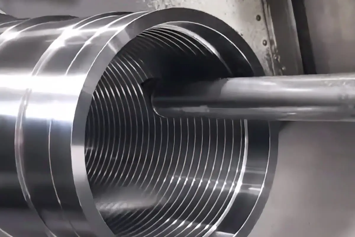
What happens when a CNC machine tool malfunctions? The intricate systems of CNC machinery, which are crucial for modern manufacturing, can be daunting to repair. This article delves into the essential steps and expert advice for diagnosing and fixing these complex machines. Readers will gain insights into effective observation techniques, critical questions to ask, and practical troubleshooting methods, ensuring they can tackle CNC repairs with confidence and precision.

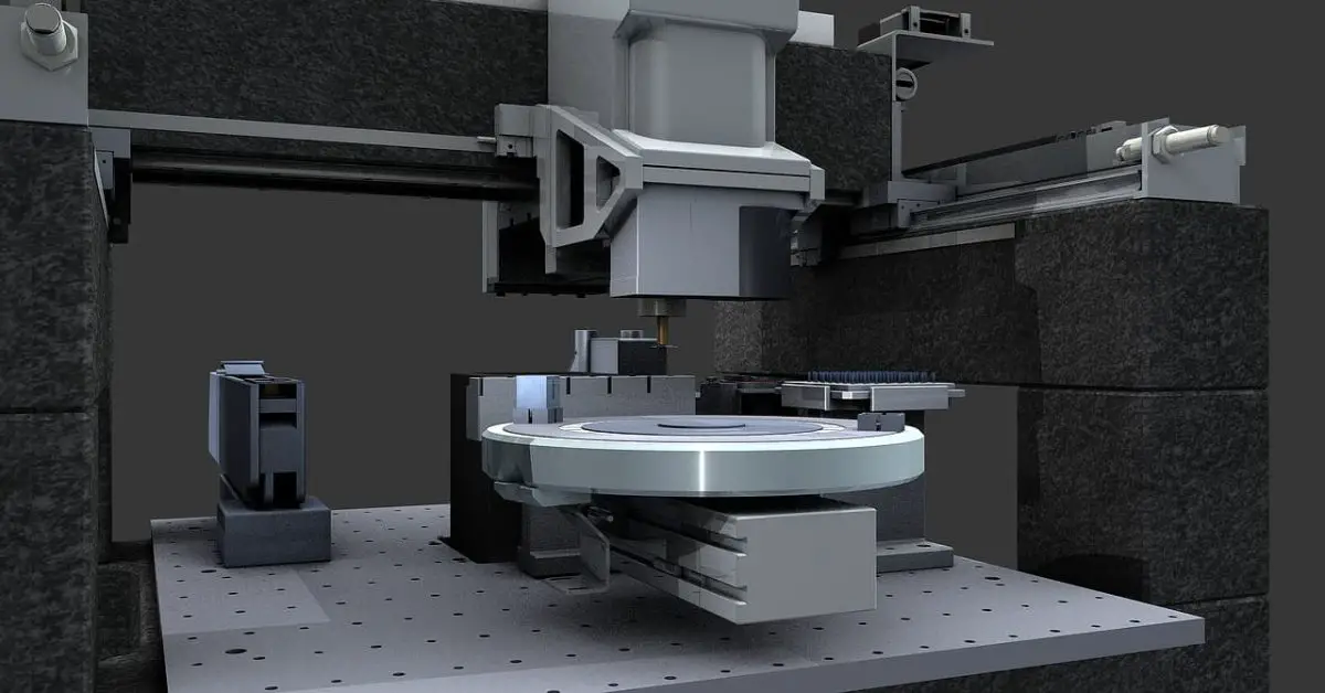
As we are aware, CNC machine tools are advanced and high-tech products that have evolved from the 1970s to the 1990s and cannot be interchanged. The fault phenomena are unique and different, particularly with large and heavy CNC machine tools, which are expensive, costing several million dollars each and requiring a long installation and adjustment time, ranging from a few months to over a year.
Large-scale CNC machine tools have thousands of components, and a failure of any one of them can result in abnormal machine tool behavior and issues with wire and pipe connections. Even a small oversight can lead to problems. Furthermore, these large-scale and heavy-duty CNC machine tools are bulky in size and are often used in non-temperature-controlled environments, making them vulnerable to environmental impacts that can cause failures.
As a result, the issue of “challenging maintenance” of CNC machine tools is brought to the forefront. With so many CNC machine tools imported and manufactured in China, how can we promptly identify faults and potential dangers and resolve them in a timely manner? How can we repair these costly equipment?
In my opinion, first and foremost, we must have a strong sense of responsibility and the determination to overcome difficulties. Second, we should strive to master numerical control technology and draw upon my over ten years of experience in repairing numerical control machine tools.
We should observe more, ask more questions, remember more, think more critically, and practice more to gradually improve our technical level and maintenance capability to handle complex situations and repair numerical control machine tools effectively.
To observe more, we should:
Gain an understanding of the features and functions of various CNC systems and PLC programmable controllers.
Acquire knowledge of the alarm and troubleshooting methods of the CNC system.
Learn the significance of NC and PLC machine tool parameter setting.
Become proficient in the programming language of PLC.
Gain an understanding of NC programming methods.
Familiarize ourselves with the operation of the control panel and the details of each menu.
Understand the capabilities of the spindle and cutter motor, as well as the characteristics of the driver, etc.
But when there is a large amount of numerical control data, how do we make a choice?
The most important aspect is to emphasize the crucial elements and provide clear context.
It is essential to comprehend the fundamental composition and structure of the CNC system and be proficient in the block diagram.
While the rest of the information can be reviewed, each component should be thoroughly understood and given due importance.
Given that the internal circuit diagram of the CNC system is quite intricate and the manufacturer may not provide it, there is no need to delve into its details.
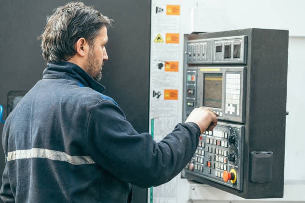
For instance, the NX-154 four-axis five-link blade processing machine utilizes the A-B10 system.
It’s crucial to comprehend the role of each component, the function of each board, the purpose of the interface, the significance of the LED lights, etc.
There are numerous types of CNC systems that are constantly being updated.
Different manufacturers and models often have significant variations.
It’s important to understand their similarities and differences.
Typically, those familiar with the maintenance of the Siemens CNC system may not be experts in troubleshooting the A-B system.
Therefore, it’s necessary to continue learning and updating knowledge.
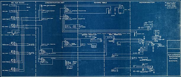
Each electrical component, such as a contactor, relay, time relay, etc., and the inputs and outputs of the PLC should be clearly indicated on the electrical diagram.
For example, 1A1 represents the contactor that starts the hydraulic pump motor 1M.
The location of its normally open and normally closed contacts is typically indicated on the diagram.
Thus, the normally open or normally closed contact 1A1 can be marked with the hydraulic pump motor being on.
The electrical diagram for large-scale CNC machine tools can have dozens or even hundreds of pages, making it time-consuming to understand the function of each component.
You may not immediately understand the function of a component after reading it once or twice, so it’s important to read it multiple times and take notes.
The starting hydraulic pump motor 1M should also clearly indicate which external output of the PLC drives the action of the contactor 1A1, making the context clear.
For certain block diagrams in the electrical circuit diagram, such as the driver for each axis, only a block diagram is provided.
However, as long as you understand the control condition (on-off condition), you can spend time studying and examining the details.
It’s important to note that electrical symbols vary between countries.

It’s crucial to have a clear understanding of them.
For the comprehensive PLC statement tables provided by the manufacturer, it’s important to spend time reading and mastering their programming language, annotating, and translating them into Chinese based on your understanding.
This can significantly reduce the time required for troubleshooting in the future.
If you become familiar with the electrical diagram and PLC statement table only after a fault occurs, it will take a significant amount of time and may result in incorrect judgment.

For the mechanical, hydraulic, and pneumatic diagrams of CNC machine tools, it’s important to understand their functions and context.
It’s necessary to note on the drawing that, for example, the installation process for accessories and tools on the German COBURG CNC gantry milling machine is relatively complex.
The diagram should be broken down, such as which solenoid valve is responsible for locking the tool, and what are the corresponding PLC inputs and outputs.
The electrical and mechanical actions should be clearly indicated in the figure, making it easy to understand at a glance.
At the same time, special attention should be given to the components that have a close relationship between the machine and electricity.
For example, the Italian INNSE CNC milling machine adopts electro-hydraulic proportional valve technology, and it’s important to focus on understanding its function, particularly its adjustment method and data.
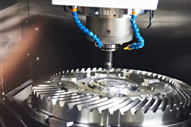
In both static and dynamic scenarios, it’s important to understand the proportional valve current and corresponding balance pump pressure, as well as the integration of electricity, machinery, and electromechanics.
By mastering a diverse range of skills, it greatly enhances the ability to solve problems.

If you do not have proficiency in foreign languages, especially English, it can be challenging to comprehend a large amount of foreign technical materials.
Simply relying on translation is often not an ideal solution.
Reading technical materials in a foreign language can be difficult at first, as there are many new terms to learn.
However, with continued reading and memorization, it becomes smoother as there are only a limited number of commonly used professional words.
A competent maintenance professional should have a basic mastery of language tools.

If you have the opportunity to attend training abroad or if foreign experts come to your factory to install and debug machine tools, it’s best to participate.
This is the ideal learning opportunity, as you can obtain a wealth of first-hand information and machine tool debugging techniques and skills.
For instance, after laser measuring the accuracy of each axis, learn how to correct it electrically, etc.
Ask plenty of questions, and make sure to clarify any misunderstandings.
Through this experience, you will gain a lot, including access to internal information and confidential user manuals.
Once the machine tool is put into formal production, it’s important to maintain close contact with relevant foreign experts.
Through fax and email, it’s valuable to seek guidance on how to solve challenging faults with the machine tool and to obtain special spare parts.
It’s also important to maintain a good relationship with the agents of the CNC system, such as Siemens and FANUC, by asking questions and obtaining timely information and relevant spare parts for the CNC system.

Additionally, we can take advantage of opportunities to participate in specialized courses on the CNC system.
When a fault occurs, it’s important to thoroughly ask the operator about the entire process leading to the fault.
Failing to gather accurate field data can result in incorrect judgments and complicate the issue.
Therefore, it’s necessary to ask detailed questions to understand the entire process of the fault, including the start, middle, and end, the alarm number generated, the components that were in use, any changes made, and the external environment.
Based on a thorough investigation of the scene and thorough understanding of first-hand materials, it’s crucial to accurately list the fault problems, effectively solve the problems that have already been identified, and then analyze and resolve the remaining issues.
Experienced and skilled operators are familiar with the operation of machine tools, processing procedures, and common problems.
Close collaboration with them is very beneficial for rapid troubleshooting.
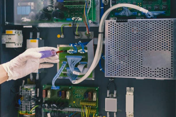
When other maintenance personnel are repairing a machine tool and you are not present, once they return, it’s important to ask questions about the recent repair. Inquire about their troubleshooting process and how they solved the issue.
This is a valuable learning opportunity. You can learn the correct troubleshooting techniques and methods from others, especially experienced maintenance personnel, and improve your knowledge and skills.

It’s important to focus on recording various relevant parameters after the machine tool has been adjusted, such as NC machine tool parameters, PLC machine tool parameters, and PLC programs (which can be stored on disk), as well as the current, voltage, speed, and other data of the spindle and each tool feeding motor.
Additionally, it’s necessary to record the status (on or off) of relays, contactors, etc. in the electrical cabinet during power-on and formal processing, as well as the status (lit, dark, flashing) of all PLC inputs and output LED lights, or whether the PLC status IB (input bit) and QB (output bit) on the screen is 0 or 1, for example, IB1=:00000001, meaning I1.0=1 and I1.1-1.7=0.
This record is extremely helpful for future analysis and fault judgment.
For instance, if the Z-axis motor current relay action occurs on a German Schiess CNC vertical lathe, these records will be beneficial.

By quickly checking the PLC state (0 or 1) of the Z-axis motor during normal operation and comparing it to the abnormal state, the cause of the fault was easily identified.
It was found that one of the comparison relays was in the incorrect state.
With adjustment, the fault was resolved promptly.
Similarly, it’s important to record the readings of various pressure gauges and barometers, as well as the suction and disconnection state of solenoid valves during normal and non-normal hydraulic and pneumatic processing. This information is extremely helpful for adjustment and fault judgment.
For example, the static pressure of an American Ingersoll openside masterhead CNC milling machine utilizes double film technology and has over 100 pressure measurement points.
The level of pressure directly impacts the normal operation of the machine tool functions, making it crucial to record both static and dynamic pressure.

It’s important to keep a record of the faults that occur each day, along with the process of how they were resolved. The human mind can easily forget things over time, so having a written record is extremely beneficial.
It has been observed that some faults in CNC machine tools often recur and are always the same faults. By reviewing how they were solved in the past, these faults can be quickly resolved in a matter of minutes.
It’s recommended to maintain a “CNC machine tool operation diary” and a “CNC machine tool troubleshooting record book”. These two materials should be well documented.
This creates a complete historical file of the CNC machine tool.

Sometimes, it can be challenging to diagnose a repair issue, as there may not be a clear analysis available.
I recall a situation where the Y-axis of a Coburg gantry milling machine stopped unexpectedly during operation and the screen displayed multiple 1361Y-axis grating dirty alarms. Despite cleaning the grating ruler and head, the machine remained shut down.
It took several days to identify the root cause, which was eventually determined to be a problem with the wire connecting the Y-axis grating head and the EXE amplifier. Over time, the serpentine tube had become bent, causing one of the position feedback lines to break, resulting in the machine’s stoppage.
At the time, we only focused on the machine’s static state and overlooked its dynamic state. There was an open circuit alarm 1321 control circuit, but we failed to give it adequate attention.
To prevent similar issues in the future, it is important to keep a record of all alarms and faults that occur and conduct a comprehensive evaluation by eliminating false possibilities and focusing on the most likely cause. By doing so, we can better predict potential faults and take steps to resolve them.
“At the end of the journey, there is a brighter destination waiting, but it requires careful consideration to reach it.” Let’s think more deeply to find the solution.
When troubleshooting, it can be frustrating when the root cause of a problem remains elusive, leading to persistent faults.
I recall an instance where the main shaft SL of an Ingersoll rotor blade root slot milling machine experienced frequent “automatic shutdowns” after running for just two hours. A foreign expert attempted to fix the issue by replacing the sequence board, and it appeared to be successful, but the problem reoccurred after a month.
Although replacing the standby board of the sequence board seemed like a solution, the underlying cause was not clear. After a careful inspection, we discovered that the reverse peak voltage of the optocoupler corresponding to the “start” command was abnormally high with the help of an oscilloscope. We were able to fix the issue by adding a ground wire, which significantly reduced the reverse peak voltage of the optocoupler.
Since then, the “automatic shutdown” fault has not recurred as the high reverse peak voltage was causing the optocoupler to fail gradually over time.
Spare parts for machinery and electrical appliances should be carefully selected based on their frequency of use, repeatability, and expected service life. This is crucial to maintain continuous and normal operation of the machine tool.
In some cases, the delay in replacement or difficulty in obtaining the spare parts can lead to their unavailability or high cost in the market. To address this, it’s important to consider this in advance and plan accordingly.
For instance, a photoelectric reader used in CNC machine tools in the early 1980s required a belt to read the processing program in loop mode and select the original data in spool mode. If the belt became unavailable, it would render the entire machine tool inoperable, resulting in serious consequences. To overcome this issue, we collaborated with relevant units and after several tests, adopted a floppy disk processor, ensuring the continued use of the machine tool.
It’s important to think ahead, provide reasonable suggestions to leaders, and strive to improve the external environment of CNC machine tools by considering factors such as temperature, dust, humidity, etc. This can be achieved through measures like installing power regulators, electric cabinets, and air-conditioned enclosures, which can significantly reduce the failure rate of machine tools.

Maintenance personnel must exhibit a combination of boldness and caution while performing their duties. Simply talking about repairing CNC machine tools is not enough; they must take action to perform the repair effectively.
However, it is important not to act blindly without being familiar with the situation, as this could exacerbate the fault and result in a potentially dangerous accident.
In addition to being bold and cautious, maintenance personnel must also be skilled in hands-on tasks.
To begin, they should familiarize themselves with the machine tool’s control panel and understand the functions of each menu. This knowledge will allow them to operate the various models and systems with ease.
They should also make the most of the CNC machine tool’s self-diagnosis technology to quickly detect and resolve faults.
Thanks to advancements in numerical control technology, self-diagnosis capabilities are becoming increasingly sophisticated. For instance, the A-B10 system has specialized diagnostic software that can be connected to a network for remote diagnosis.
Sometimes, faults can appear ambiguous and it can be challenging to determine whether the issue is electrical or mechanical in nature.
For instance, the Coburg gantry milling machine has encountered such a fault, where regardless of whether the z-axis is being raised or lowered, the z-axis ram always moves downward and triggers an alarm.
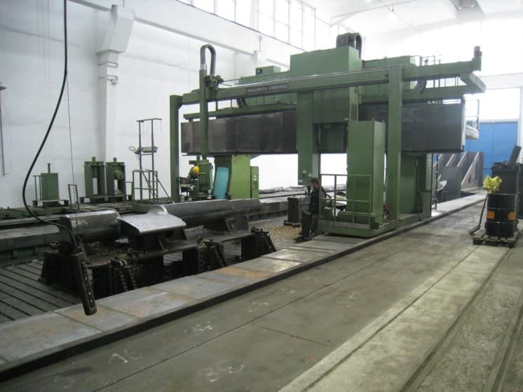
We employed the “separation method” to resolve the issue. This method completely isolated the control of the electrical component from the original circuit. We disconnected the wiring terminal of the z-axis DC motor, and connected the DC power, which was derived from the AC 220V power supply through voltage regulation and four-diode rectification, to the two ends of the motor.
By doing so, we discovered that the electrical function changed the direction of rotation based on the conversion of polarity in the DC power, effectively eliminating the electrical fault.
Upon further inspection, we found that the fault was actually caused by the slipping of the mechanical friction plate and sagging of the ram.
There are several other methods, such as the “isolation method,” “replacement method,” “comparison method,” and “percussion method,” that can be used to effectively locate and resolve faults.
There are various tools that can assist in judging and checking specific circuits, such as an oscilloscope, multimeter, online circuit detector, short circuit detector, computer, programmer, and more. These tools, particularly the PLC programmer and computer, can be especially helpful in these efforts.
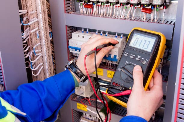
Maintenance personnel should be proficient in using these tools and have the ability to input and output machine parameters, perform online testing of relevant states, and initiate system initialization.
This expertise will greatly aid in the analysis of faults, especially complex faults, and enable the resolution of problems.
When a component, such as a selector switch, button, or relay, is damaged during normal operation and there are no spare parts available, try to temporarily repair it using adhesives or other special methods to ensure the machine tool can continue to operate until the spare parts arrive.
For instance, the German VDF CNC cart has five miniature pressure switches for clamping in the second knife back. If two of these switches are accidentally damaged and there are no spare parts available, temporary repair methods should be used.
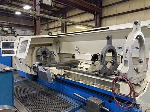
We utilized the “short-circuit method” to make the pressure switch’s contact meet the input requirements of the PLC, allowing the machine tool to operate normally without any alarms.
Over time, the machine’s poor positioning accuracy may result in a positioning alarm. In such cases, the machine parameters can be temporarily adjusted by increasing the “tolerance” zone, allowing it to work normally.
Our years of maintenance experience has shown us that foreign-designed CNC machine tools, particularly large ones, are not perfect and often have problems and defects. Through our studies and improvements to CNC machine tools, we have been able to address these issues and achieve positive results.
For example, the German VDF CNC cart was originally designed with two static pressure brackets that were always operational and the static pressure pump ran continuously, consuming electricity and reducing the lifespan of the imported pump. By adding two switches, we were able to modify the PLC and control the operation of the two static pressure brackets, extending the lifespan of the imported pump and saving over 20,000 kWh of electricity annually.
In another instance, the original design of the Ingersoll impeller slot milling machine only allowed for reverse milling with the main and auxiliary heads. However, when machining the 20th stage impeller of the high and intermediate pressure rotor, reverse milling was not possible due to the small distance between the impellers. We solved this issue by cleverly changing the two-way limit wiring and adding to the PLC program, allowing for same-direction milling. This doubled our work efficiency and allowed us to complete the task of processing rotors 3-4 days in advance.
In conclusion, we should continue to tap into the potential of CNC machine tools and fully utilize their capabilities to serve production.
In general, the circuit board of a CNC machine tool is reliable with a low failure rate. When conducting a check on the CNC machine tool, it is not advisable to immediately suspect a problem with the board.
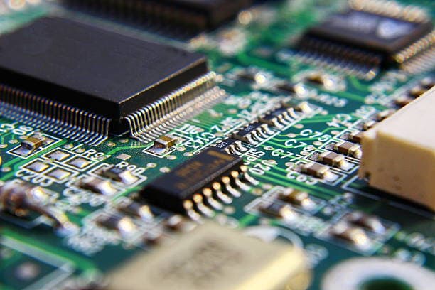
In the Siemens 850 system, alarms such as 41nc-cpu and 43plc-cpu may occur. These alarms are not necessarily indicative of a problem with the circuit board.
They can often be resolved through various methods, such as repeated testing, removal procedures, NC initialization, cold and hot starts of the PLC, and others. If a circuit board issue is determined to be the cause, it should be repaired.
The circuit boards in this system can be costly, often reaching thousands or tens of thousands of yuan, and obtaining replacement parts can be challenging for businesses. Hence, the quality of the CNC machine tool’s circuit board is critical. Any damage to the board can result in production shutdowns, as there may be no readily available spare parts.
In some cases, a minor fault in the circuit board may be the cause of an alarm. Careful inspection can often identify these issues, such as capacitor leakage, poor soldering, or short circuits. Complex faults can also be repaired with the help of instruments, given enough time.
However, some circuit boards, particularly large-scale integrated circuits, can be difficult to repair, especially if the original device does not have spare parts. In such cases, it may be necessary to purchase spare boards in advance or send them out for repair.
Self-repairing circuit boards offers several benefits for enterprises. It can save costs and provide a quick solution to urgent problems. Additionally, it can provide an opportunity to gain deeper knowledge and experience with electronic circuits, which can improve analytical judgment and practical skills.
Although the faults of CNC machine tools can be complex and constantly evolving, taking a serious approach and cultivating a high-quality electromechanical integration maintenance team can help. By observing more, asking more questions, thinking more critically, and gaining more hands-on experience, this team can accumulate knowledge and skills to effectively repair, use, and manage CNC machine tools. With dedication and perseverance, relying on their own strengths becomes possible.

