Have you ever wondered why some metal parts tear during deep drawing? It’s a common problem that can ruin production runs. This article explores the causes of tearing in deep-drawn parts and practical solutions to fix them. You’ll learn key factors that affect drawing ratios, lubrication techniques, and repair methods for different types of tears. Whether you’re new to metal forming or a seasoned pro, you’ll find valuable tips to improve your deep drawing processes.
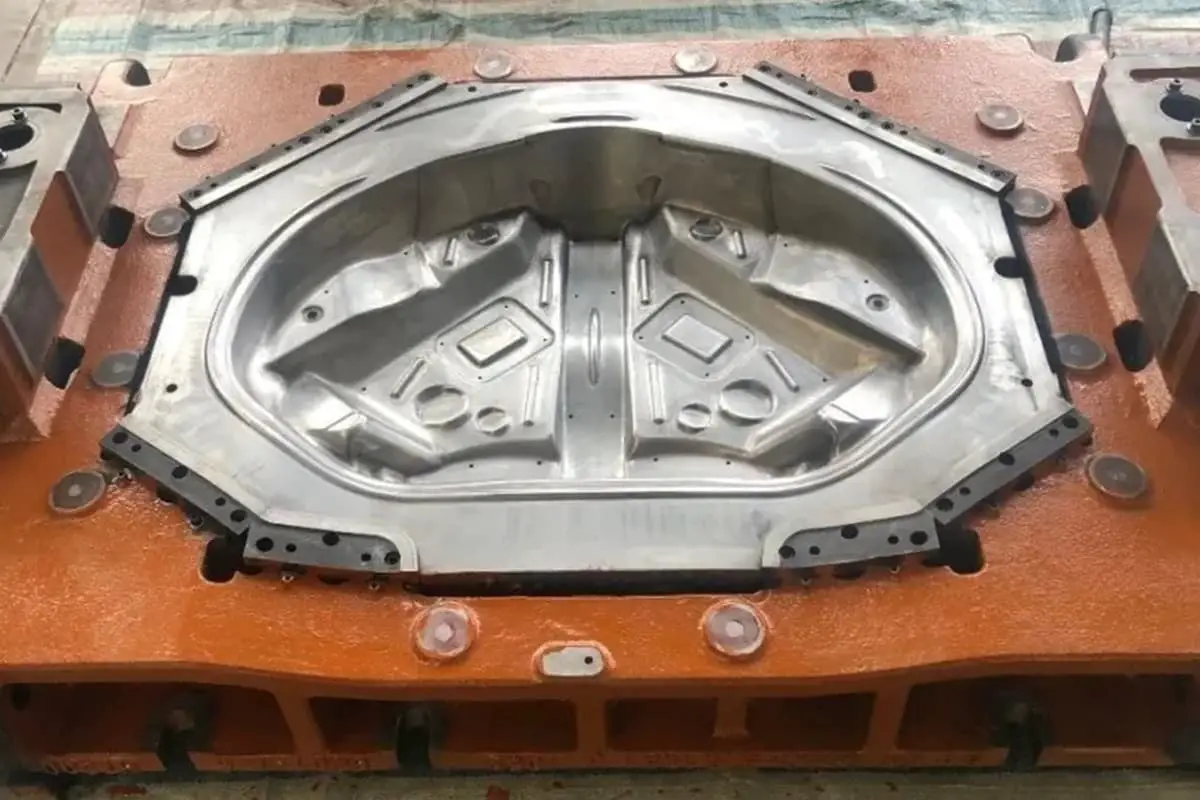
Deep drawing: Pressing sheet metal into hollow parts (wall thickness remains basically unchanged)
Deep drawing process: Material is transferred from the flat surface (flange) to the cylindrical (box-shaped) side wall, resulting in significant changes in the outer dimensions of the flat surface
Drawing ratio: The ratio “m” of the drawing diameter to the blank diameter (degree of deformation from blank to workpiece)

1) Material mechanical properties (yield strength–elastic deformation; tensile strength–plastic deformation; elongation coefficient; cross-sectional shrinkage rate)
2) Relative thickness of the material (T/D<1, D is the blank diameter)
3) Number of draws: Due to work hardening, except for intermediate annealing processes, the m value generally increases with each draw (m1
4) Drawing method: The presence or absence of a blank holder affects the m value; with a blank holder, m can be smaller; when the punch radius R is too small, it’s easier to produce dangerous cross-section fractures
5) Punch and die corner radii: A larger die radius R can reduce forming friction, but if too large, it will reduce the blank holding area and cause wrinkling
6) Surface finish of the drawing working surfaces, lubrication conditions, clearance, and drawing speed: If the drawing speed is too fast, the flange material cannot be converted into the side wall in time, easily causing fractures
The m value for cylindrical parts without flanges, whether using or not using a blank holder.
1) Where dflange/d1: The relative flange diameter should include trimming allowance
2) h1/d1 = relative height (narrow flange: dflange/d=1.1~1.4)
3) r/d1 = relative corner radius (wide flange: dflange/d>1.4)
4) t/D = relative thickness
For wide-flanged cylindrical parts, it is generally required to draw to the desired flange diameter in the first draw. At this time, a smaller m1 should be used as much as possible, i.e., utilizing full deformation capacity. In subsequent draws, the flange diameter remains unchanged (flange invariance principle)
1) For thin materials with drawing depth greater than diameter: Use the method of reducing cylindrical diameter to increase height, corner radius can be gradually reduced
2) For thicker materials with drawing depth similar to diameter: Can maintain height while gradually reducing cylindrical diameter and corner radius
3) When the flange is very large and the corner radius is very small: Should be achieved through multiple forming steps
4) When the flange is too large: If necessary, use expansion forming method. To embody the “flange invariance” principle, let the flange formed in the first draw not participate in subsequent drawing deformations. For wide flange drawing, the material entering the die in the first draw (i.e., material forming the wall and bottom) should be 3~10% more than actually needed for the final draw.
Note: Calculate the number of draws based on area; choose the upper limit for multiple draws, and the lower limit for fewer draws. This excess material will gradually return to the flange in subsequent draws, causing the flange to thicken but avoiding tearing at the top. Areas of local thinning can be corrected through forming. Therefore, strict control of drawing height in each step is very important.

The corner part is equivalent to cylindrical drawing, while the straight wall part is equivalent to bending deformation
During the drawing process, there is friction between the material and the die, with 5 types of friction forces:
A. Friction forces F1, 2, 3 oppose the drawing deformation direction, not only increasing the drawing ratio and force but also causing wear and scratches on the die and workpiece surface, so they are harmful
B. F4, 5 follow the drawing forming direction and have the effect of preventing material thinning at the dangerous cross-section, so they are beneficial. Based on this analysis, in drawing operations, the die side should be lubricated while the punch side should not. In actual production, sometimes the die and blank holder surfaces are polished as much as possible while the punch surface is intentionally roughened for drawing
C. Single-sided lubrication is only suitable for drawing certain cylindrical parts and not suitable for various drawing formations in the entire drawing process (such as shallow cylindrical parts, box-shaped parts, and curved parts mainly formed by expansion)
Double-sided lubrication for box-shaped part drawing
From a deformation perspective, cylindrical part drawing deformation is uniform, requiring smooth deformation in the deformation zone and minimizing plastic deformation in the force transmission zone to improve forming limits. At this time, only single-sided lubrication can meet the requirements
However, in box-shaped part drawing, due to the non-uniform deformation characteristics in the deformation zone, using double-sided lubrication conditions can exploit the deformation potential of the force transmission zone to compensate for the non-uniformity of these two deformation zones. This can both improve the load-bearing capacity of the force transmission zone and promote smooth plastic deformation of the entire deformation zone, thus achieving a certain degree of improvement in the forming limit of box-shaped parts.
1) Types of tears:
2) Repair methods
1: “A, B” Neck and top tear cause analysis:
1) Insufficient height in the previous draw (too little material drawn in)
2) Die corner radius too small or transition between R corner and straight surface not smooth. Countermeasures:
1) Appropriately increase the height of the previous draw
2) Polish the die corner radius and appropriately increase the R corner
2: “C” Top corner tear cause analysis:
1) Insufficient punch height in the previous draw
2) Punch R corner too small (relative to the previous draw), material at the corner cannot withstand too large a degree of instantaneous transformation
3) Dimension A of the previous draw punch smaller than the current draw. Countermeasures:
1) Appropriately increase the punch height of the previous draw
2) Appropriately increase the punch R corner and modify dimension A (ensure it’s greater than or equal to the previous draw)
3: “D” Edge tear cause analysis:
1) Process hole too close to the drawn wall
2) Punch R corner too large or too smooth (reduced friction causes excessive material flow at the bottom)
3) Insufficient blank holding force at the bottom. Countermeasures:
1) Relocate the process hole
2) Reduce the punch R corner and intentionally roughen it slightly
3) Increase the spring force of the floating insert in the die
4: Second draw tear
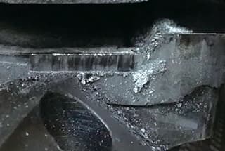
Cause: The transition from the first to the second draw is too large, and the material cannot withstand the instantaneous pressure during conversion, resulting in fracture.
Countermeasure: Grind a slope on the top of the first draw punch (as shown in the figure)
5: Drawing wrinkle repair method cause analysis:
1) Insufficient flange holding force
2) Insufficient flange holding area
3) Material accumulation caused by tearing during drawing. Countermeasures:
1) Increase stripper plate spring strength (red springs recommended)
2) Increase stripper plate pre-compression amount (1 T+0.02~0.04mm)
3) First repair the tear
1) When repairing tears, first check the flange deformation amount in the first draw—maximize the conversion of flange material into side wall material.
2) Determine the drawing height for each draw. When confirming the drawing height for each draw, use the punch height as the standard (and keep a record). *Use the height of the last draw punch as the baseline (if the current product height is OK); the second-to-last draw should be 0.10~0.20mm higher than the last draw; previous draws should gradually decrease.
3) Check the surface finish of the die working surface.
4) When repairing tears, consider and analyze the causes comprehensively. Do not “treat the symptoms without addressing the root cause.”

