What happens when a rivet suddenly fails after minimal use? This article delves into the unexpected fatigue fracture of rivets, exploring the causes, stress analysis, and how misalignment and external factors can lead to failure. Readers will gain insight into the intricate details of rivet stress behaviors and the importance of proper assembly to prevent such issues. By the end, you’ll understand how engineering practices can mitigate these failures and ensure structural integrity.
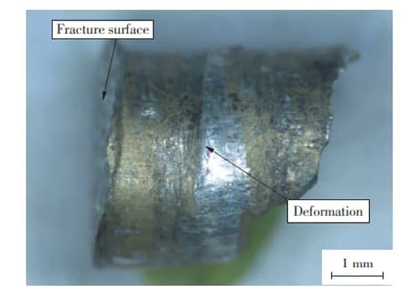
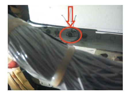
After 90 hours of operation, a broken rivet head was discovered at the junction between the 15a frame and the inlet skin.
Observations and analysis of the fracture surface, including macro and micro observations, metallography, hardness testing, and fatigue stress calculation, revealed that the rivet failure was caused by fatigue fracture.
A deviation in the alignment of the mounting hole between the frame and skin connected by the rivet resulted in an imbalance between normal bending and shear stress, compounded by the added stress from air flow vibrations. This led to an increase in the initial stress on the rivet, causing it to fracture.
The results of the fracture surface analysis also showed that the rivet experienced a higher level of fatigue initial stress and a lower level of expansion stress.
Riveting offers several benefits, including a straightforward process and equipment, resistance to vibration and impacts, consistent force transmission, and durability and dependability.
As a result, riveting is a commonly used method of connection.
To complete the riveting process, first align the connected parts and place them in their proper position. Then, line up the rivet holes and insert the rivets. Finally, use a tool to form the heads of the rivets and secure the rods in place.
The load is transferred through the friction force on the contact surface of the connectors, as the rivet is drawn together by the connecting tool.
Common modes of stress and failure in rivets include:
The two main failure types in rivet design are shearing of the rivet rod and extrusion or collapse of the metal at the compression point between the rivet and the connected parts.
In the production process, improper heat treatment control is the main cause of rivet failure, both domestically and internationally. This may result in coarse grains, overburning, or the presence of brittle phases in the raw materials.
During the upsetting process, high shear strength or cracking of the rivet head may occur during the riveting process. Abnormal external forces can also lead to shearing of the rivet.
Fatigue failure in rivets is rare due to their connection mode, stress state, and other characteristics. However, abnormal assembly and other stress conditions during practical engineering applications may result in fatigue failure, causing the failure of the fastening connection and increasing the opening displacement. This may also lead to abnormal stress in nearby rivets and result in fatigue failure of the connection.
Conducting a failure analysis of rivet fatigue is crucial. This can be done through visual observation, macro and micro examination of the fracture surface, metallography, hardness testing, and other methods.
By combining the results of fracture surface analysis and estimation, this study reverses the crack growth characteristics and initial equivalent comprehensive stress of engineering riveted components, providing data support for the stress characteristics and size of the components. This information is helpful in determining the root cause of failure and solving practical engineering problems.
The first rivet head at the connection between the 15a frame and the inlet skin was discovered to have fallen off after 90 hours of service, which is equivalent to 130 take-offs and landings (as shown in Fig. 1).
The rivet material is LY10 aluminum alloy, a medium strength duralumin with a tensile strength of 390 MPa and high shear strength of 235 MPa. This material has sufficient plasticity for riveting under various conditions, such as annealing, quenching, aging, and hot conditions. It is commonly used for the manufacture of medium strength rivets and structural parts.
The rivet was broken at the arc transition of the head.
From the side damage, it can be seen that the junction of the two connecting plates at the straight section of the rivet was severely deformed, indicating a deviation in the coaxiality of the mounting holes between the frame and the skin (as shown in Figure 2).
Place the fractured rivet under a scanning electron microscope for microscopic examination.
The source of the rivet fracture is located on its outer surface (as seen in Figure 3a).
The source area exhibits steps and extended edges, forming a large linear source that covers approximately one sixth of the circumference.
No metallurgical defects or processing traces were identified in the source area (as shown in Figures 3b and 3c).
During the crack growth phase, numerous small fatigue arcs and strips can be observed (as seen in Figure 3d), with the crack growing primarily through fatigue, accounting for over 95% of the total cross-sectional area.
An energy spectrum analysis of the rivet fracture source area and expanded area revealed the absence of any foreign elements.
The side of the fracture source area was also examined, and it was found that the surface anodized protective film was intact (as shown in Figure 3e).

The metallographic and hardness inspection of the rivet revealed no abnormalities in its metallography and a relatively uniform hardness value.
The fracture of the rivet occurs at the transition point between the rivet head and the arc, and there are numerous small fatigue arcs and fatigue strips visible on the fracture surface.
This indicates that the failure of the rivet is due to fatigue.
The fracture takes place at the initial riveting location of the connecting structure, which is the connection between frame 15a and the air inlet skin.
If the riveting process is abnormal, the first rivet is more susceptible to failure, which aligns with the general principle of fastener failure in riveting.
In general, the most common mode of failure for rivets as fasteners is shear fracture.
When fatigue fracture occurs at the arc of the rivet head, it shows that its riveting function has been altered to some degree.
During proper assembly, there should be an interference fit between the rivet and the connecting plate’s rivet hole, leading to minimal or no stress at the arc transition of the rivet head.
The observations show that the junction between the two connecting plates in the straight section of the rivet is severely deformed, indicating a deviation in the coaxiality of the mounting holes between the frame and the skin, resulting in abnormal assembly stress on the rivet.
Under the combined effect of abnormal assembly stress and air flow vibration stress, the rivet experiences fatigue cracking.

The surface of a fractured rivet exhibits a large line source, and the size of the source area can indicate the magnitude of the initial stress to a certain degree, allowing for a preliminary assessment that the initial stress leading to the rivet fracture was significant.
The crack in the rivet is fully expanded, and the fatigue area covers more than 95% of the total fracture area, suggesting that the initial stress on the rivet was substantial, but the expansion stress was relatively low.
Since the location of the rivet fracture is at the stress concentration point at the transition of the arc of the rivet head, when the alternating stress is low, its fatigue cracking may also exhibit line source characteristics. Therefore, it is necessary to quantitatively reconstruct the fracture surface to deduce the comprehensive initial stress that the rivet bore.
Under normal operations, the rivet is interference fitted, and the stress at the arc fracture position is either low or non-existent under force.
However, the rivet is susceptible to fatigue fractures, primarily due to the bending alternating stress it experiences at the arc of the rivet head, caused by the up and down movement of the connecting plate, leading to the formation of a semi-elliptical surface crack.
By referencing the stress intensity factor model of “semi-elliptical surface crack under uniform tension and bending” in literature, the model assumes a round rod sample with diameter D that contains semi-elliptical surface cracks. The major axis of the crack is 2a, the semi-minor axis of the crack depth is b, and the stress intensity factor of the front edge of the crack under uniform tension and bending stress σ is calculated using the bending condition of the center of the stress intensity factor model (as shown in Fig. 4).
Therefore, the stress intensity factor at each point on the crack front edge is:


Fig.4 Model of round column specimen,half ellipse surface crack and uniform tension
Refer to Table 1 and Figure 5 for the comprehensive stress data of rivet quantitative analysis.
As shown in Fig. 5, the maximum comprehensive equivalent stress decreases continuously with an increase in crack length, and the reduction rate also decreases.
Given the limited data, we conservatively estimate the initial fracture stress by fitting a linear regression between the crack length and stress data, yielding the equation Y=273-10.5x.
When x=0, Y=273 MPa, representing the maximum comprehensive equivalent stress at the start of the rivet, which is approximately 70% of the tensile strength (390 MPa) of the LY10CZ aluminum alloy.
It is important to note that the rivet material is LY10 aluminum alloy and it experiences a fatigue stress ratio of R=-1. The material constants c and n were not found, so we used the crack growth constant for LY12 aluminum alloy’s stress ratio (R=0.25) for reverse inference in the quantitative estimation.
Please note that there may be errors in the initial maximum comprehensive equivalent stress value.
The main focus of this study is to present the stress analysis method.
Table 1 quantitative analysis results of fatigue stress of the rivet
| No. | b/a | B/mm | Y | S/μ | △σ/MPa | σmax/MPa |
| 1 | 0.31 | 0.53 | 0.987 | 0.08 | 200.9 | 267.9 |
| 2 | 0.71 | 1.40 | 0.782 | 0.08 | 192.5 | 256.7 |
| 3 | 0.81 | 1.78 | 0.782 | 0.10 | 191.5 | 255.4 |

Fig.5 Linear fiting of length and stress
With the crack propagation and vibration displacement of the upper and lower connecting plates remaining constant, the stress on the rivet gradually decreases, as does the stress at the crack tip. This corresponds to 95% of the full fatigue range of the rivet’s crack propagation.
Consequently, the fracture of the rivet is a fatigue fracture characterized by a high initial stress but relatively low expansion stress.

