Ever wondered how something as simple as a screw thread can impact the world of engineering? From ancient Greece to modern machinery, screw threads have been crucial in transforming rotational motion into linear action. This article dives into their history, types, and standards, unraveling the complexities of thread profiles and measurements. You’ll discover how threads play a vital role in fastening and power transmission, ensuring mechanical efficiency and safety. Get ready to learn the fundamentals and intricacies of screw threads and their significance in mechanical design.
The concept of the spiral form, fundamental to threading, has been recognized since ancient times. As early as the 4th century BC, Greek naturalists utilized this principle in devices for extracting wine and oil, demonstrating an early understanding of helical mechanics.
One of the most enduring applications of this concept is the Archimedes’ screw, a water-lifting device invented in the 3rd century BC. This ingenious mechanism continues to find use in modern water management and irrigation systems, testament to its efficiency and simplicity.

Fig. 1 Archimedes spiral water intake device still in use today
The evolution of threading technology saw significant advancement by the 14th century, with the emergence of handcrafted threads and screws. These early threaded components, while rudimentary, laid the groundwork for future mechanical innovations.
The Industrial Revolution marked a pivotal moment in the history of threading. As machinery became increasingly complex, the need for reliable mechanical fasteners grew exponentially. Bolts, in particular, became crucial for assembling and maintaining various industrial equipment.
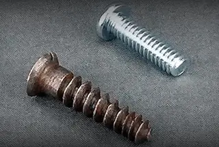
Initially, threading was a labor-intensive process. Nuts, bolts, and screws were individually crafted by skilled artisans using hand tools or basic lathes. This method, while functional, had significant limitations:
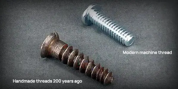
Fig. 2 handmade threads 200 years ago vs modern machine threads
The need for efficiency and consistency drove the development of standardized threading systems. Various countries began establishing their own unified standards, eventually leading to international standardization efforts. This standardization revolutionized manufacturing, enabling mass production and interchangeability of parts across industries and geographical boundaries.
Today, two primary thread measurement standards dominate global manufacturing:
China, aligning with international practices, has fully embraced the metric system. In Chinese manufacturing and engineering, thread measurements and specifications are consistently expressed in metric millimeters (mm). This adoption facilitates seamless integration with global supply chains and adherence to international engineering standards.
The history of threading reflects broader trends in technological advancement, standardization, and global industrial cooperation. From ancient Greek ingenuity to modern precision manufacturing, the evolution of threading continues to play a crucial role in mechanical engineering and industrial progress.
A thread is a continuous helical ridge formed by winding around a cylindrical or conical surface in a spiral pattern. This helical structure enables the conversion of rotational motion into linear motion, facilitating the controlled linear displacement of objects.
Threads can be classified into two main types based on their surface geometry:
Tapered threads: Created on conical surfaces, with a gradually changing diameter.
Straight threads: Formed on cylindrical surfaces, maintaining a constant diameter along their length.
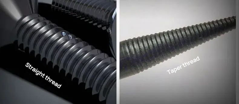
Fig. 3 straight and tapered threads
Threads are further categorized as external or internal:
The mating of external and internal threads enables secure fastening or precise linear actuation through rotational engagement. This interlocking mechanism forms the basis for a wide range of mechanical connections and motion transfer applications in engineering and manufacturing.
A complete description of the thread should include at least five elements, namely:
The tooth profile is the key factor to determine the end use of thread.
Tooth shape refers to the geometry of the thread.
Different tooth shapes determine whether the thread is used for connection or transmission.
Currently, the commonly used tooth types mainly include triangle, trapezoid, sawtooth, and rectangle.
The triangle thread is mainly used for connection, while the other three tooth patterns are used for power transmission.
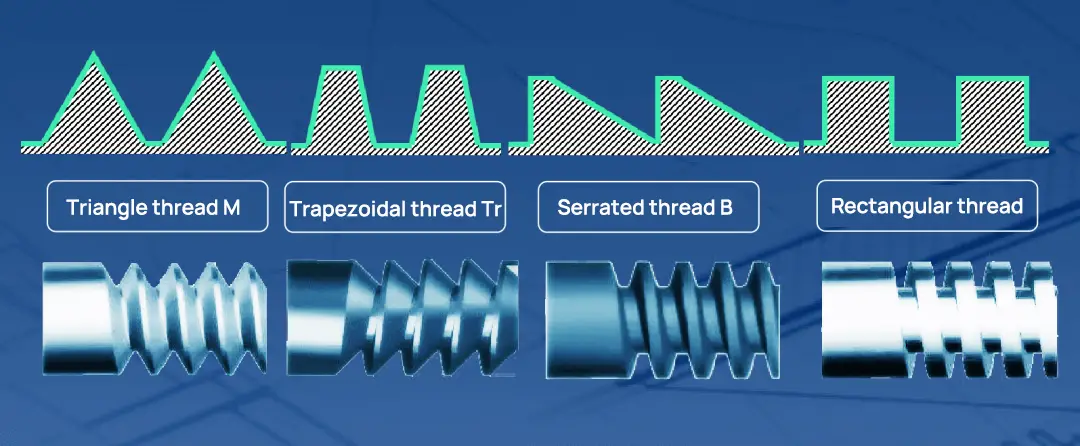
Fig. 4 Comparison of four common thread types
The triangle thread consists of two main types of threads: ordinary thread code M and pipe thread code G.
The M thread is the most commonly used connecting thread, and it is classified into coarse teeth and fine teeth. Fine teeth are usually employed for small or thin-walled parts.
On the other hand, pipe threads are used for connecting water pipes, gas pipes, and other pipelines.
The trapezoidal thread with code Tr is utilized for power transmission in various machine tool lead screws.
The serrated thread with code B is capable of transmitting power in only one direction.
Figure 5 displays the classification of threads according to their use and tooth type.
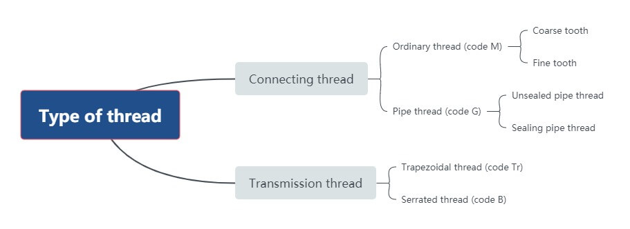
Fig. 5 Classification of threads
The thread size is typically determined by the nominal diameter. However, for pipe threads, the nominal diameter is the inner diameter of the pipe (in inches), while for other threads, it is the major diameter (in metric units).
External threads are denoted by the uppercase letter “D”, while internal threads are denoted by the lowercase letter “d”. The major diameter is the diameter of an imaginary cylinder that is tangent to the crest of an external thread or the root of an internal thread. Conversely, the minor diameter is the diameter of an imaginary cylinder that is tangent to the root of an external thread or the crest of an internal thread.
The pitch diameter is a crucial parameter for achieving thread fit and strength. It is the diameter of an imaginary cylinder whose tooth width on the pitch line is equal to the adjacent tooth width.

Fig. 6 large, medium and small diameter of external thread and internal thread
The number of thread refers to the number of spiral lines when forming threads, which can be divided into single line and multi line.
Single thread refers to the thread formed along one spiral line, and multi thread refers to the thread formed along two or more spiral lines.

Fig. 7 single and double line thread
The axial distance P between the corresponding two points on the pitch diameter line of two adjacent teeth on the thread is called the pitch;
On the same thread, the axial distance Ph between the corresponding two points of two adjacent teeth on the pitch diameter line is called the lead.

Fig. 8 pitch and lead
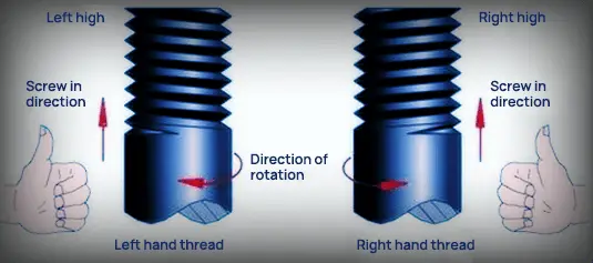
Fig. 9 thread direction
The prevailing standards of threads in various countries are mainly the measurement and identification standards of class 2 threads in metric units and inch units.
The metric screw thread was first adopted in Central France between 1898 to 1908, and then it was widely promoted across various countries.
In China, the GB metric screw thread standard is adopted.
The metric thread code M is applicable for connecting workpieces with a diameter ranging from 0.25mm to 300mm.
The thread angle is 60°, and the top of the tooth is flat, which makes it easy to turn, while the bottom of the tooth is a circular arc that enhances the thread’s strength.
The metric thread can be classified into two categories: coarse thread and fine thread.
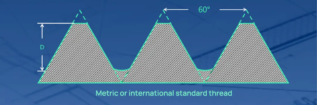
Fig. 10 metric thread standard
Originated in Britain, this thread was invented by British citizen Joseph Whitworth in 1841, hence its name.
The thread angle of this thread is 55 °, and the top and bottom of the thread are circular arc, also known as b.s.w thread.
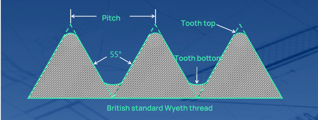
Fig. 11 British standard Wyeth thread standard
The thread shape of this type is similar to that of a B.S.W thread, and the thread angle is also 55°. However, it has a higher number of threads per inch, resulting in a thinner thread thickness and a stronger grip.
This type of thread is commonly used for parts that require strong roots or need to withstand high levels of vibration.
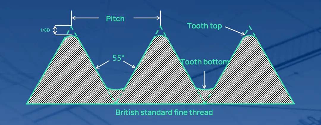
Fig. 12 British standard fine thread standard
The American Standard thread has a flat top and bottom, providing good strength and stress resistance.
The thread angle measures 60° and its specification is expressed in teeth per inch, categorized into three levels: coarse teeth (NC), fine teeth (NF), and super fine teeth (NEF).
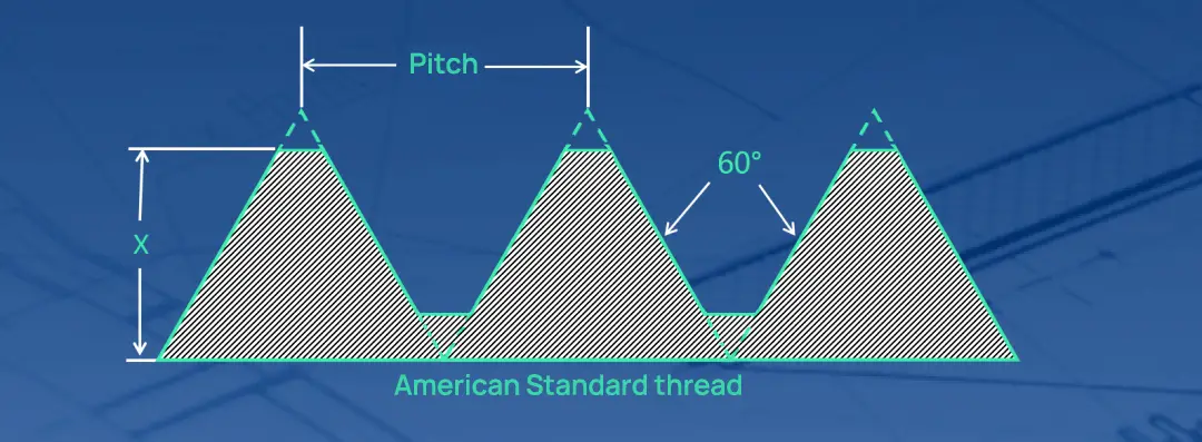
Fig. 13 American Standard thread
The British thread, which is currently commonly used, was developed by the United States, Britain, and Canada.
In contrast to the American Standard thread, the British thread has a thread angle of 60° and its specifications are expressed by the number of teeth per inch. Additionally, it is divided into three levels: coarse tooth (UNC), fine tooth (UNF), and ultra-fine tooth (UNEF).
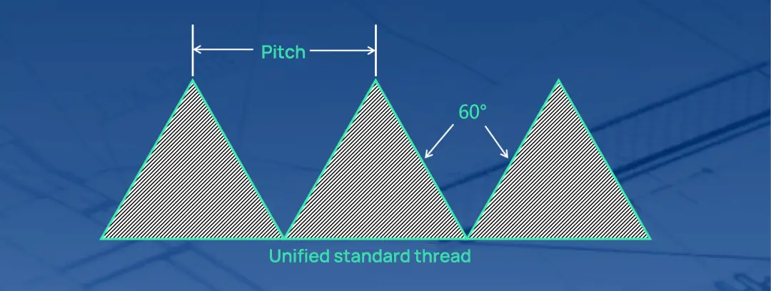
Fig. 14 unified thread standards of the United States, Britain and Canada
It is the standard thread determined by din in Germany.
The thread is round, which is suitable for the connection of bulbs and rubber tubes.
The thread code is Rd.
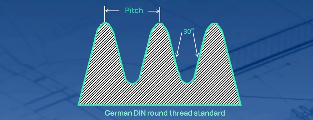
Fig. 15 German DIN round thread standard
Trapezoidal thread, also known as acme thread, is a special transmission thread that can be adjusted by nut after wear.
The thread angle when the metric thread standard is used is 30 °, and the thread angle when the British thread standard is used is 29 °.

Fig. 16 Trapezoidal Tr thread
According to China’s GB standard, the unit of measurement for ordinary thread marking is millimeters. The first letter indicates the thread code, while the second digit represents the nominal diameter, also known as the major diameter of the thread. The remaining symbols represent the tolerance code, screw length code, and screw direction code, respectively.
It is mandatory to mark the fine pitch, while the coarse pitch may be omitted.

Fig. 17 marking contents of 5 parts of ordinary thread
Code notes of each part:
The feature code represents the type of thread, with M representing an ordinary thread. The size code indicates the nominal diameter × pitch. For instance, 8X1 means that the nominal diameter is 8 and the pitch is 1.
The tolerance zone code comprises a tolerance grade (number) and a basic deviation. The external thread is represented by lowercase letters, and the internal thread is represented by uppercase letters.
The Screwing Length code uses L, N, and s to represent long, medium, and short, respectively. When the thread is of medium screwing length, the code N is not marked.
The rotation direction code is marked with LH for left-hand thread and not marked for right-hand thread.
Example interpretation
Example 1: what thread does M20x1.5LH-5g6g-S represent?

Example 2: what kind of thread does B36x14 (P7) -7H-L refer to?

Example 3: how to represent left-hand single thread fine thread ordinary thread with nominal diameter of 20 and pitch of 1.5?

The thread can be customized by three methods: numerical control turning, three-axis linkage milling and tapping and threading.
Method 1 NC turning
NC turning with turning tool is the most commonly used customized processing method for single piece and small batch of threaded workpieces because of its simple structure.
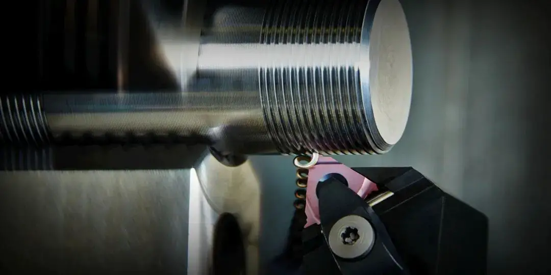
Fig. 18 customized machining of turning thread
Method 2 NC Milling
In general, milling is performed using disc milling cutters or comb milling cutters.
Disc milling cutters are primarily utilized for milling trapezoidal external threads on workpieces like screw rods and worms. On the other hand, comb milling cutters are employed for milling both internal and external ordinary threads or conical threads.
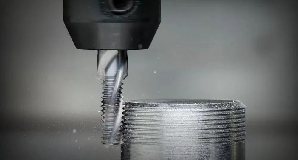
Fig. 19 customized processing of NC milling thread
Method 3 tapping and threading
Tapping is to use a certain torque to screw the tap into the pre drilled bottom hole on the workpiece, so as to process the required internal thread.
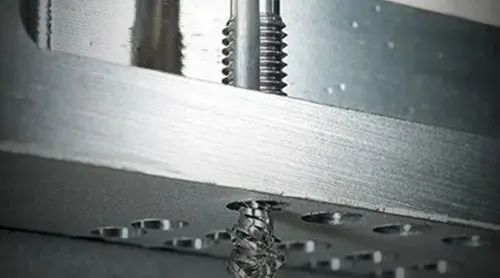
Fig. 20 tapping
Threading is a forming method of cutting external thread on bar workpiece with die.
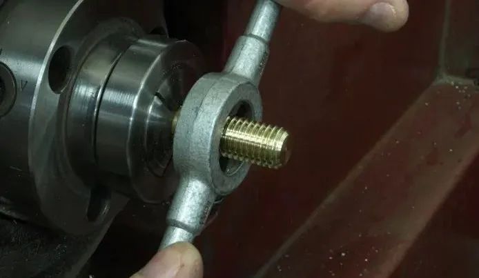
Fig. 21 threading
On one hand, the accuracy of tapping and threading depends on the precision of the tap or die used, while on the other hand, it also relies on the experience of the operator performing the task.
For several non-standard small-diameter internal threads, tapping is the only feasible method of processing.
Tapping and threading can be carried out manually or by utilizing machines such as lathes, drilling machines, tapping machines, or threading machines.

