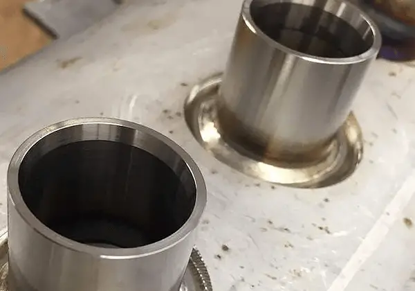
Have you ever wondered how fuel tanks and oil drums are seamlessly welded together? Seam welding, a fascinating technique using roller electrodes, is the key. In this article, you’ll uncover how this method works, its applications, and the benefits it offers in creating strong, sealed joints in various industries. Get ready to explore the intriguing world of seam welding!
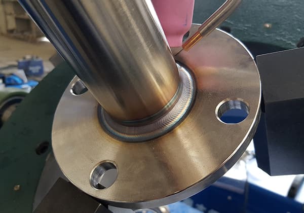
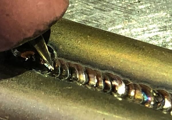
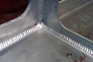
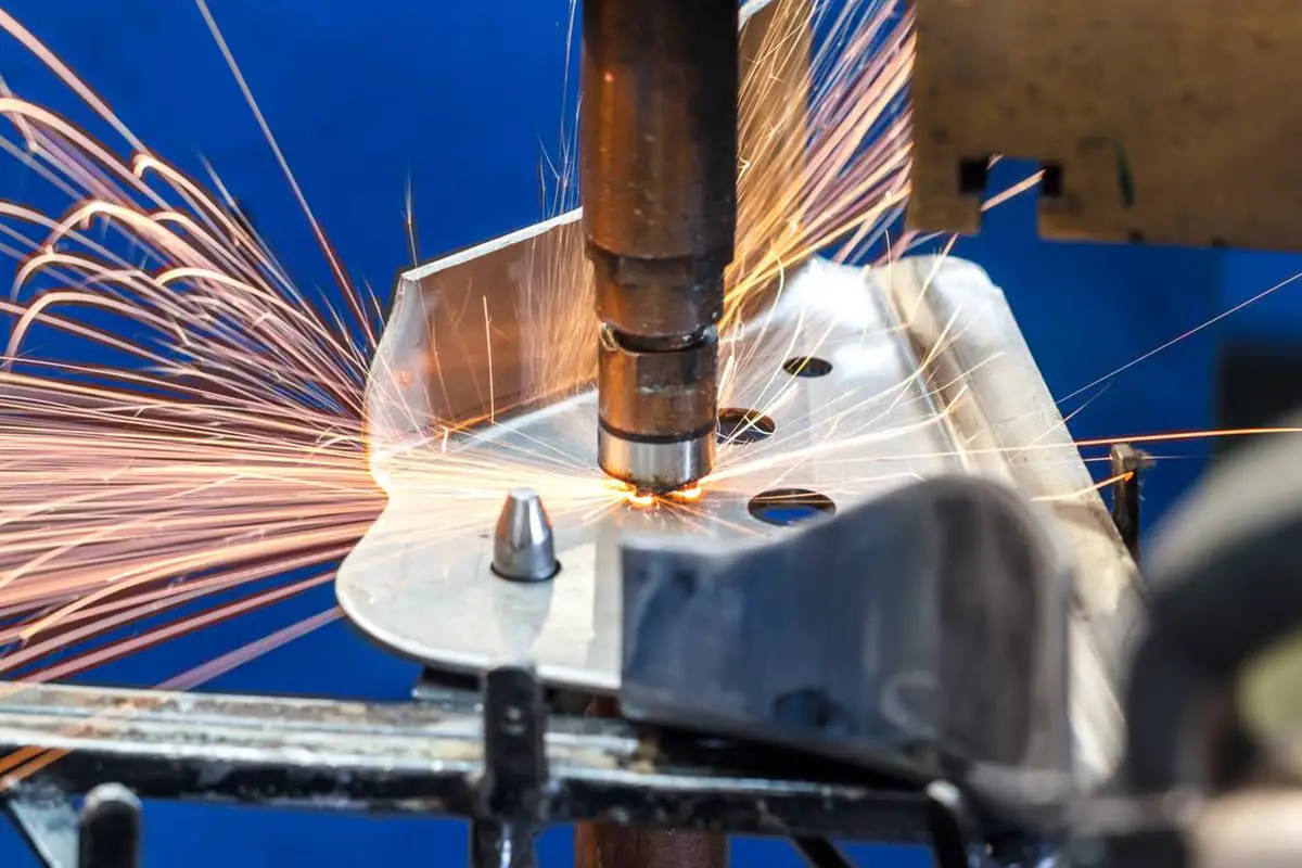
Seam welding is an advanced continuous resistance welding technique that utilizes a pair of rotating wheel-shaped electrodes instead of the stationary cylindrical electrodes employed in spot welding. As the electrodes roll along the workpiece, they generate a series of overlapping weld nuggets, resulting in a hermetically sealed, continuous weld seam.
This process involves the application of both pressure and electric current to create localized heating at the interface of the materials being joined. The heat generated by the electrical resistance of the workpieces causes them to melt and fuse together, while the applied pressure ensures proper contact and helps expel impurities from the weld zone.
Seam welding is particularly effective for joining thin-gauge metals, typically ranging from 0.5 to 3 mm in thickness. It offers several advantages, including high production speeds, excellent leak-tight properties, and minimal distortion of the workpieces. The process can be easily automated and integrated into high-volume manufacturing lines.
This welding method finds widespread application in the fabrication of sealed containers and critical components across various industries. It is commonly used in the production of:
Recent advancements in seam welding technology include the integration of real-time monitoring systems for weld quality control, the development of specialized electrode materials for improved durability and conductivity, and the implementation of adaptive control algorithms to optimize welding parameters on-the-fly.
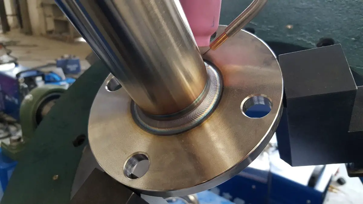
The electrode used in seam welding is a circular roller with a diameter ranging from 50 to 600mm, with 180-250mm being the most common range. The roller thickness typically falls between 10-20mm.
Two primary contact surface geometries are employed: cylindrical and spherical, with conical surfaces occasionally utilized for specialized applications.
Cylindrical rollers can feature either double-sided or single-sided chamfers, the latter being particularly suited for seam welding folded edges. The contact surface width (ω) varies from 3-10mm, correlating with the workpiece thickness. For spherical rollers, the radius of curvature (R) ranges from 25-200mm.
Cylindrical rollers find widespread use in welding various steels and high-temperature alloys due to their versatility. Spherical rollers, on the other hand, are preferred for light alloys owing to their superior heat dissipation characteristics and uniform pressure distribution, which minimizes indentation and reduces the risk of material deformation.
During operation, rollers are typically cooled externally. For non-ferrous metals and stainless steel welding, clean tap water suffices as a coolant. When welding carbon steels, a 5% borax water-soluble solution is commonly employed to prevent oxidation and extend electrode life. In some cases, particularly with aluminum alloy welding machines, internal circulating water cooling systems are implemented for more efficient heat management, although this configuration significantly increases the complexity of the electrode design and overall system.
Based on the rotation and feeding methods of the roller, seam welding can be divided into continuous seam welding, intermittent seam welding, and step seam welding.
In continuous seam welding, the roller continuously rotates and the current continuously passes through the workpiece. This method easily causes overheating of the workpiece surface and severe electrode wear, and therefore is rarely used. However, in high-speed seam welding (4-15m/min), a weld spot is formed every half cycle of the 50Hz AC current, and the zero crossing of the AC current is equivalent to a rest time, which is similar to the following intermittent seam welding. Therefore, it has been applied in the cylinder and barrel manufacturing industry.
In intermittent seam welding, the roller continuously rotates, and the current intermittently passes through the workpiece, forming a seam composed of overlapping fusion cores. Due to the intermittent current, the roller and workpiece can cool down during the rest time, which can improve the roller’s lifespan, reduce the width of the heat-affected zone and workpiece deformation, and achieve better welding quality.
This method has been widely used in seam welding of various steels, high-temperature alloys, and titanium alloys below 1.5mm. However, in intermittent seam welding, the fusion core crystallizes under reduced pressure when the roller leaves the welding area, which can easily cause surface overheating, shrinkage holes, and cracks (such as when welding high-temperature alloys).
Although the melted metal of the latter point can fill the shrinkage hole of the previous point when the overlap amount of the weld spot exceeds 50% of the fusion core length, the shrinkage hole of the last point is difficult to avoid. However, this problem has been solved by domestically developed microcomputer control boxes, which can gradually reduce the welding current at the beginning and end of the weld seam.
In step seam welding, the roller intermittently rotates, and the current passes through the workpiece when it is stationary. Since the melting and crystallization of the metal occur when the roller is stationary, the heat dissipation and compression conditions are improved, which can effectively improve the welding quality and prolong the lifespan of the roller. This method is mostly used for seam welding of aluminum and magnesium alloys.
It can also effectively improve the welding quality of high-temperature alloys, but it has not been applied in China because this type of AC welding machine is rare.
When welding hard aluminum and various metals with a thickness of 4+4mm or more, step seam welding must be used to apply forging pressure to each weld spot like spot welding, or both warm and cold pulses must be used simultaneously. However, the latter case is rarely used.
According to the type of joint, fillet welding can be divided into lap joint welding, pressure flat joint welding, shim joint welding, copper wire electrode joint welding, etc.
Like spot welding, lap joint welding can be welded with a pair of rollers or with a roller and a core electrode. The minimum lap of the joint is the same as that of spot welding.
In addition to the commonly used double-sided seam welding, there are also single-sided single-seam welding, single-sided double-seam welding, and small diameter circumferential seam welding in lap joint welding.
Small diameter circumferential seam welding can be done with
1) rollers electrode that deviates from the pressure axis;
2) a positioning device attached to the transverse seam welding machine;
3) a ring-shaped electrode whose workpiece surface is conical and whose tip must fall on the center of the small diameter circumferential weld to eliminate the sliding of the electrode on the workpiece.
The lap of pressure flat joint welding is much smaller than that of general seam welding, about 1-1.5 times the plate thickness. During welding, the joint is simultaneously flattened and the thickness of the joint after welding is 1.2-1.5 times the plate thickness.
Typically, cylindrical roller faces are used, covering the entire lap portion of the joint. To obtain stable welding quality, the lap must be precisely controlled, and the workpiece must be firmly clamped or pre-fixed with a locating weld. This method can produce welds with a good appearance and is commonly used for welding products such as food containers and freezer liners made of low carbon steel and stainless steel.
Shim joint welding is a method for solving thick plate seam welding. Because when the plate thickness reaches 3mm, if a conventional lap joint welding is used, a slow welding speed, large welding current, and electrode pressure are required, which can cause surface overheating and electrode adhesion, making welding difficult. If shim joint welding is used, these difficulties can be overcome.
The shim joint welding is simply introduced as follows:
First, the edges of the panel parts are joined together, and when the joint passes through the roller, two strips of foil are constantly laid between the roller and the panel. The thickness of the foil is 0.2-0.3mm, and the width is 4-6mm. Since the foil increases the resistance of the welding zone and makes heat dissipation difficult, it is beneficial to the formation of the molten core.
The advantages of this method are:
The disadvantages are: high accuracy requirements for joint; during welding, the foil must be laid between the roller and the workpiece, which increases the difficulty of automation.
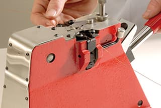
Copper wire electrode joint welding is an effective method to solve the adhesion of the coating to the roller in the seam welding of coated steel plates. During welding, the round copper wire is continuously fed between the roller and the plate.
The copper wire is in a spiral shape and is continuously fed through the roller and then wound onto another spool. The coating only adheres to the copper wire and does not contaminate the roller.
Although the copper wire needs to be scrapped after use, there is no other seam welding method that can replace it for coated steel plates, especially tin-plated steel plates. Since the scrap value of copper wire is similar to that of the copper wire, the welding cost is not high. This method is mainly used for manufacturing food cans.
The formation of a butt weld joint is essentially the same as that of a spot weld, and therefore the factors affecting welding quality are similar. The main factors include welding current, electrode pressure, welding time, pause time, welding speed, and roller diameter.
The heat required to form a molten pool in a butt weld joint is generated by the resistance of the welding area to the flow of current, which is the same as in spot welding. Under given conditions, the welding current determines the fusion penetration and overlap of the molten pool. For welding low-carbon steel, the average fusion penetration of the molten pool is 30-70% of the plate thickness, with 45-50% being optimal. To obtain a gas-tight butt weld, the overlap of the molten pool should be no less than 15-20%.
When the welding current exceeds a certain value, increasing the current will only increase the fusion penetration and overlap of the molten pool without improving the joint strength, which is uneconomical. If the current is too high, it can also cause defects such as excessive indentation and burn-through.
Due to the significant diversion caused by the overlap of molten pools in a butt weld, the welding current is usually increased by 15-40% compared to spot welding.
The effect of electrode pressure on the size of the molten pool in butt welding is the same as in spot welding. Excessive electrode pressure will cause excessive indentation and accelerate the deformation and wear of the roller. Insufficient pressure is prone to porosity and can cause the roller to burn out due to excessive contact resistance, shortening its service life.
In butt welding, the size of the molten pool is mainly controlled by the welding time, and the overlap is controlled by the cooling time. At lower welding speeds, a welding-to-pause time ratio of 1.25:1-2:1 can achieve satisfactory results. When the welding speed increases, the distance between welds increases, so the ratio must be increased to achieve the same overlap. Therefore, at higher welding speeds, the welding-to-pause time ratio is 3:1 or higher.
Welding speed is related to the metal being welded, plate thickness, and the strength and quality requirements of the weld. Lower welding speeds are typically used when welding stainless steel, high-temperature alloys, and non-ferrous metals to avoid spatter and obtain high-density welds. Sometimes, stepwise butt welding is used to perform the entire molten pool formation process while the roller is stationary. The welding speed of this type of butt welding is much lower than that of intermittent butt welding.
Welding speed determines the contact area between the roller and the plate, as well as the contact time between the roller and the heating area, thereby affecting the heating and cooling of the joint. When the welding speed increases, the welding current must be increased to obtain sufficient heat. Excessive welding speed can cause surface burn-out of the plate and electrode adhesion, limiting the welding speed even with external water cooling.
The optimization of seam welding process parameters is critical for achieving high-quality welds and is primarily influenced by the material properties, thickness, quality requirements, and available equipment. While initial parameter selection can be based on recommended data, fine-tuning through experimental trials is essential for optimal results.
Roller size selection follows principles similar to electrode selection in spot welding. Recent trends favor narrow rollers with contact surface widths of 3-5mm, offering several advantages:
The interaction between roller geometry and workpiece characteristics significantly impacts weld quality:
1. Roller diameter and plate curvature:
2. Asymmetric configurations:
When welding dissimilar thicknesses or materials, nugget displacement correction methods are analogous to spot welding techniques. Strategies include:
For seam welding of plates with significant thickness differences:
To optimize seam welding processes:
By carefully selecting and fine-tuning these parameters, manufacturers can achieve high-quality seam welds with optimal strength, appearance, and efficiency across a wide range of applications and material combinations.
The design principles for groove weld butt joints share similarities with those of lap joints and spot welding, with notable exceptions in flattened groove welding and shimmed groove welding techniques. However, a key distinction lies in the tooling: unlike spot welding electrodes, seam welding rolling wheels cannot be customized into specialized shapes. This limitation necessitates careful consideration of rolling wheel accessibility when designing structures for groove welding.
When welding workpieces with small radii of curvature, a significant challenge arises. The minimum achievable radius of the inner rolling wheel is constrained, which can lead to an outward shift of the molten weld pool. In extreme cases, this displacement may result in inadequate fusion of the outer plate, compromising joint integrity.
To mitigate these issues, it is advisable to avoid designs featuring excessively small radii of curvature whenever possible. However, in applications where both flat sections and areas with very small radii of curvature are unavoidable—such as in motorcycle fuel tank fabrication—adaptive welding parameters can be employed. Specifically, increasing the welding current when processing the small-radius sections can help ensure complete fusion and penetration.
This adaptive approach is particularly feasible with modern microcomputer-controlled welding systems, which offer precise, real-time adjustment of welding parameters. These systems can be programmed to automatically modulate current, voltage, and travel speed based on the geometry being welded, ensuring consistent weld quality across varying contours.
Furthermore, for optimal results in groove welding of complex geometries:
By integrating these design considerations and advanced welding technologies, manufacturers can achieve high-quality groove weld butt joints across a wide range of geometries, ensuring both structural integrity and aesthetic quality in the final product.
Low-carbon steel is the best material for seam welding due to its excellent weldability. For lap seam welding of low-carbon steel, high-speed, medium-speed, and low-speed schemes can be adopted depending on the purpose and usage.
The welding conditions for lap seam welding of low-carbon steel are shown in the table below. When manually moving the workpiece, medium speed is often used to facilitate alignment with the predetermined welding position.
When welding automatically, high speed or higher speeds can be used if the welding machine’s capacity is sufficient. If the capacity of the welding machine is not enough and high width and depth of fusion cannot be guaranteed without reducing the speed, then low speed must be used.
Welding conditions for low-carbon steel seam welding
| Plate thickness(mm) | Roller size(mm) | Electrode force(KN) | Minimum overlap(mm) | High speed welding | Medium speed welding | Low speed welding | |||||||||||||
|---|---|---|---|---|---|---|---|---|---|---|---|---|---|---|---|---|---|---|---|
| Minimum b | Standard b | Maximum B | minimum | standard | Minimum b | Standard b | Welding time (week) | Rest time (week) | Welding current (KA) | Welding speed (cm/min) | Welding time (week) | Rest time (week) | Welding current (KA) | Welding speed (cm/min) | Welding time (week) | Rest time (week) | Welding current (KA) | Welding speed (cm/min) | |
| 0.4 0.6 0.8 1.0 1.2 1.6 2.0 2.3 3.2 | 3.7 4.2 4.7 5.1 5.4 6.0 6.6 7.0 8.0 | 5.3 5.9 6.5 7.1 7.7 8.8 10.0 11.0 13.6 | 11 12 13 14 14 16 17 17 20 | 2.0 2.2 2.5 2.8 3.0 3.6 4.1 4.5 5.7 | 2.2 2.8 3.3 4.0 4.7 6.0 7.2 8.0 10 | 7 8 9 10 11 12 13 14 16 | 10 11 12 13 14 16 17 19 20 | 2 2 2 2 2 3 3 4 4 | 1 1 1 2 2 1 1 2 2 | 12.0 13.5 15.5 18.0 19.0 21.0 22.0 23.0 27.5 | 280 270 260 250 240 230 220 210 170 | 2 2 3 3 4 5 5 7 11 | 2 2 2 3 3 4 5 6 7 | 9.5 11.5 13.0 14.5 16.0 18.0 19.0 20.0 22.0 | 200 190 180 180 170 150 140 130 110 | 3 3 2 2 3 4 6 6 6 | 3 3 4 4 4 4 6 6 6 | 8.5 10.0 11.5 13.0 14.0 15.5 16.5 17.0 20.0 | 120 110 110 100 90 80 70 70 60 |
The following two tables show the welding conditions for continuous electric lap welding and backing strip welding of low-carbon steel.
Welding conditions for low-carbon steel seam welding
| Plate thickness(mm) | Overlap(mm) | Electrode force(KN) | Welding current(KA) | Welding speed(cm/min) |
| 0.8 1.2 2.0 | 1.2 1.8 2.5 | 4 7 11 | 13 16 19 | 320 200 140 |
Welding conditions for low-carbon steel backing strip welding
| Plate thickness(mm) | Electrode force(KN) | Welding current(KA) | Welding speed(cm/min) |
| 0.8 1.0 1.2 1.6 2.3 3.2 4.5 | 2.5 2.5 3.0 3.2 3.5 3.9 4.5 | 11.0 11.0 12.0 12.5 12.0 12.5 14.0 | 120 120 120 120 100 70 50 |
When welding quench-hardened alloy steel, a post-weld heat treatment is also required to eliminate quenching structure, which should be performed using a dual-pulse heating method.
During welding and tempering, the workpiece should not move and should be done on a step-seam welding machine. If this equipment is not available and only intermittent seam welding machine is available, it is recommended to use longer welding time and weaker conditions. The following table shows the recommended values for welding quenched alloy steel using these conditions.
Welding Conditions for Low Alloy Steel Seam Welding
| Plate thickness(mm) | Roll disc width(mm) | Electrode force(KN) | Time (week) | Welding current(KA) | Welding speed(cm/min) | |
|---|---|---|---|---|---|---|
| welding | cease | |||||
| 0.8 1.0 1.2 1.5 2.0 2.5 | 5-6 7-8 7-8 7-9 8-9 9-11 | 2.5-3.0 3.0-3.5 3.5-4.0 4.0-5.0 5.5-6.0 6.5-8.0 | 6-7 7-8 8-9 9-10 10-12 12-15 | 3-5 5-7 7-9 8-10 10-13 13-15 | 6-8 10-12 12-15 15-17 17-20 20-24 | 60-80 50-70 50-70 50-60 50-60 50-60 |
Note: The rolling diameter is 150-200mm.
When seam welding galvanized steel plates, attention should be paid to prevent cracking and damaging the air tightness of the weld. The reason for cracking is that the zinc remaining in the fusion zone and diffusing into the heat-affected zone makes the joint brittle, which is then subjected to stress. The method to prevent cracking is to select the correct process parameters.
Tests have shown that the smaller the weld penetration rate (10-26%), the smaller the crack defects. High seam welding speed can lead to poor heat dissipation, overheating of the surface, and greater melting depth, which can easily cause cracking. Generally, under the conditions of ensuring the fusion diameter and joint strength, small current, low welding speed, and strong external water cooling should be selected as much as possible.
Rollers can easily use flower steel wheel transmission to adjust the size and clean the surface of the rollers at any time. The table below shows the welding conditions for galvanized steel plate seam welding.
Welding conditions for various types of galvanized steel plate seam welding
| Type and thickness of coating | board thickness(mm) | Roll disc width(mm) | electrode force(KN) | Time (week) | welding current(KA) | Welding speed(cm/min) | |
|---|---|---|---|---|---|---|---|
| welding | cease | ||||||
| Hot dip galvanized(15-20um) | 0.6 0.8 1.0 1.2 1.6 | 4.5 5.0 5.0 5.5 6.5 | 3.7 4.0 4.3 4.5 5.0 | 3 3 3 4 4 | 2 2 2 2 1 | 16 17 18 19 21 | 250 250 250 230 200 |
| Silver Top(2-3um) | 0.6 0.8 1.0 1.2 1.6 | 4.5 5.0 5.0 5.5 6.5 | 3.5 3.7 4.0 4.3 4.5 | 3 3 3 4 4 | 2 2 2 2 1 | 15 16 17 18 19 | 250 250 250 230 200 |
| Calcium phosphate treated antirust steel plate | 0.6 0.8 1.0 1.2 1.6 | 4.5 5.0 5.0 5.5 6.5 | 3.7 4.0 4.5 5.0 5.5 | 3 3 3 4 4 | 2 2 2 2 1 | 14 15 16 17 18 | 250 250 250 230 200 |
The welding conditions for the first type of galvanized steel plate seam welding are shown in the table below:
Welding conditions for seam welding of aluminum-plated steel plates
| Plate thickness(mm) | Roll disc width(mm) | Electrode force(KN) | Time (week) | Welding current(KA) | Welding speed(cm/min) | ||
|---|---|---|---|---|---|---|---|
| welding | cease | ||||||
| 0.9 1.2 1.6 | 4.8 5.5 6.5 | 3.8 5.0 6.0 | 2 2 3 | 2 2 2 | 20 23 25 | 220 150 130 | |
For the second type of aluminum-plated steel plate, just like spot welding, the current must be increased by 15-20%. Due to the more severe adhesion phenomenon than that of galvanized steel plate, the rollers must be regularly maintained.
Aluminum-plated steel sheets are corrosion-resistant to gasoline, and are therefore often used for automotive fuel tanks. The seam welding of aluminum-plated steel sheets is similar to that of galvanized steel sheets, with the main concern being cracking issues. The process parameters can be referred to in the table below:
Welding Conditions for Galvanized Steel Sheet Seam Welding
| Plate thickness(mm) | Roll disc width(mm) | Electrode force(KN) | Time (week) | Welding current(KA) | Welding speed(cm/min) | ||
|---|---|---|---|---|---|---|---|
| welding | cease | ||||||
| 0.8 | 7 | 3.6-4.5 | 3 5 | 2 2 | 17 18 | 150 250 | |
| 1.0 | 7 | 4.2-5.2 | 2 5 | 1 1 | 17.5 18.5 | 150 250 | |
| 1.2 | 7 | 4.5-5.5 | 2 4 | 1 1 | 18 19 | 150 250 | |
Seam welding of stainless steel is less difficult and is usually done through AC welding. The table below shows the welding conditions for stainless steel seam welding:
Welding Conditions for Stainless Steel (1Cr18Ni9Ti) Seam Welding (HB/Z78-84)
| Plate thickness(mm) | Roll disc width(mm) | Electrode force(KN) | Time (week) | Welding current(KA) | Welding speed(cm/min) | ||
|---|---|---|---|---|---|---|---|
| welding | cease | ||||||
| 0.3 0.5 0.8 1.0 1.2 1.5 2.0 | 3-3.5 4.5-5.5 5.0-6.0 5.5-6.5 6.5-7.5 7.0-8.0 7.5-8.5 | 2.5-3.0 3.4-3.8 4.0-5.0 5.0-6.0 5.5-6.2 6.0-7.2 7.0-8.0 | 1-2 1-3 2-5 4-5 4-6 5-7 7-8 | 1-2 2-3 3-4 3-4 3-5 5-7 6-9 | 4.5-5.5 6.0-7.0 7.0-8.0 8.0-9.0 8.5-10 9.0-12 10-13 | 100-150 80-120 60-80 60-70 50-60 40-60 40-50 | |
During seam welding of high-temperature alloys, due to their high electrical resistivity and the repeated heating of the weld, it is more likely to cause crystal segregation and overheated structures, and even lead to burrs extruding from the workpiece surface.
To prevent this, a very slow welding speed and longer cooling time should be adopted to facilitate heat dissipation. The table below shows the welding conditions for high-temperature alloy seam welding:
Welding Conditions for Seam Welding of High-Temperature Alloys (GH33, GH35, GH39, GH44)
| Plate thickness(mm) | Electrode force(KN) | Time (week) | Welding current(KA) | Welding speed(cm/min) | |
|---|---|---|---|---|---|
| welding | cease | ||||
| 0.3 0.5 0.8 1.0 1.2 1.5 2.0 2.5 3.0 | 4-7 5-8.5 6-10 7-11 8-12 8-13 10-14 11-16 12-17 | 3-5 4-6 5-8 7-9 8-10 10-13 12-16 15-19 18-23 | 2-4 4-7 8-11 12-14 14-16 19-25 24-30 28-34 30-39 | 5-6 5.5-7 6-8.5 6.5-9.5 7-10 8-11.5 9.5-13.5 11-15 12-16 | 60-70 50-70 30-45 30-45 30-40 25-40 20-35 15-30 15-25 |
When seam welding aluminum alloy, due to its high electrical conductivity and serious diversion, the welding current needs to be increased by 15-50% compared to spot welding, and the electrode pressure needs to be increased by 10%.
Moreover, high-power single-phase AC seam welding machines will seriously affect the balance of three-phase loads on the power grid.
Therefore, domestic aluminum alloy seam welding generally uses three-phase direct current pulse or secondary rectifier step-by-step welding machines. The table below shows the welding conditions for welding aluminum alloy using the FJ-400 direct current pulse seam welding machine.
Welding conditions for seam welding of aluminum alloy
| Plate thickness(mm) | Spherical radius of rolling disc (mm) | Step distance (point distance) | LF21、LF3、LF6 | LY12CZ、LC4CS | ||||||
|---|---|---|---|---|---|---|---|---|---|---|
| Electrode force(KN) | Welding time (week) | Welding current (KA) | Points per minute | Electrode pressure (KN) | Welding time (KA) | Welding current (KA) | Points per minute | |||
| 1.0 1.5 2.0 3.0 3.5 | 100 100 150 150 150 | 2.5 2.5 3.8 4.2 4.2 | 3.5 4.2 5.5 7.0 – | 3 5 6 8 – | 49.6 49.6 51.4 60.0 – | 120-150 120-150 100-120 60-80 – | 5.5 8.5 9.0 10 10 | 4 6 6 7 8 | 48 48 51.4 51.4 51.4 | 120-150 100-120 80-100 60-80 60-80 |
In order to enhance heat dissipation, seam welding of aluminum alloy should preferably use a spherical end face roller and must be externally water-cooled.
The exceptional electrical and thermal conductivity of copper and most copper alloys presents significant challenges for seam welding processes. These properties cause rapid heat dissipation, making it difficult to achieve and maintain the necessary temperature for fusion at the weld interface. However, certain copper alloys with reduced electrical conductivity, such as phosphor bronze, silicon bronze, and aluminum bronze, can be successfully seam welded under specific conditions.
When seam welding these amenable copper alloys, process parameters must be carefully adjusted to compensate for their unique material characteristics:
It’s crucial to note that even with these adjustments, the weldability and resulting joint properties may not match those achieved with more readily weldable materials. Therefore, alternative joining methods such as brazing, soldering, or mechanical fastening should be considered for applications involving high-conductivity copper and copper alloys where seam welding proves impractical or yields unsatisfactory results.
Seam welding of titanium and its alloys requires careful consideration of their unique properties, although the process shares some similarities with stainless steel welding. The high strength-to-weight ratio, excellent corrosion resistance, and low thermal conductivity of titanium necessitate specific welding parameters and techniques.
While the general welding conditions are comparable to those used for stainless steel, several key adjustments are essential:
By adhering to these considerations and employing proper techniques, seam welding of titanium and its alloys can produce high-quality, durable welds suitable for demanding aerospace, medical, and industrial applications.

