How do you achieve precise bends in sheet metal? Understanding the molds and techniques behind this process is crucial. This article delves into various bending methods, from free bending to corrective bending, highlighting their applications and advantages. It explains how different molds, such as V-bends and U-bends, influence the accuracy and quality of the final product. By the end, you’ll grasp the essentials of selecting and utilizing bending techniques to enhance manufacturing efficiency and product quality.
The deformation methods for sheet bending can be classified into: free bending, contact bending, and corrective bending, as illustrated in Figure 1.

Free bending (Figure 1a) requires less bending force, and the shape and size of the workpiece are determined by adjusting the die width and the dead center position of the punch.
This method often results in less precision in the shape and size of the processed parts, especially in large-scale production, where the quality of the bent parts can be inconsistent. Therefore, free bending is often used for low volume production of medium-to-large sheet metal components.
In contrast, during contact bending (Figure 1b) and corrective bending (Figure 1c), the shape and size accuracy of the bent parts are guaranteed by the mold, providing higher and more stable quality.
However, these methods require more bending force, longer mold casting cycles, and higher costs. They are typically used for large-scale production of small-to-medium parts and sheet metal components where higher quality is required.
Generally, bending methods can be divided into mold bending (which includes top plate bending and no top plate bending) and press brake bending.
Press brake bending is a special case of mold bending (without top plate bending), typically using a universal bending mold. Both bending methods have their respective principles, characteristics, and applicability.
(1) Mold Bending
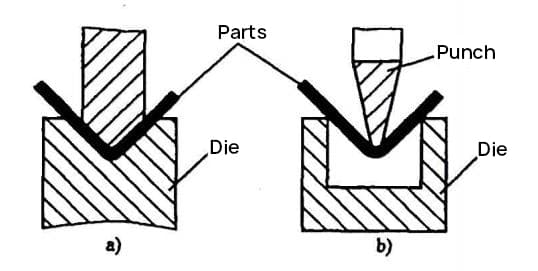
Mold bending is commonly used for sheet metal bending parts that require complex structures, smaller volumes, higher precision, and large-scale processing. The principle of a simple, common bending mold is shown in Figure 2. To extend the life of the mold, the design of the part should use a radius (r>0.5t) at the bending point whenever possible.

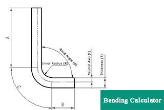
Related: V & U-shaped Bend Force Calculator
(2) Press Bake Bending
Press brake bending is commonly used for the processing of sheet metal bending parts that are larger in size or not produced in large quantities. Press brakes can be divided into ordinary press brake and CNC press brake.
For sheet metal bending parts with relatively high precision requirements and complex shapes, CNC press brakes are generally used for bending processing. The basic principle of bending, such as cold-bent open-section steel and sheet metal bending parts of chassis, cabinets, and electronic products, is to use the bending blade (top punch) and V-shaped groove (lower die) of the press brake to bend the plate, as shown in Figure 3.

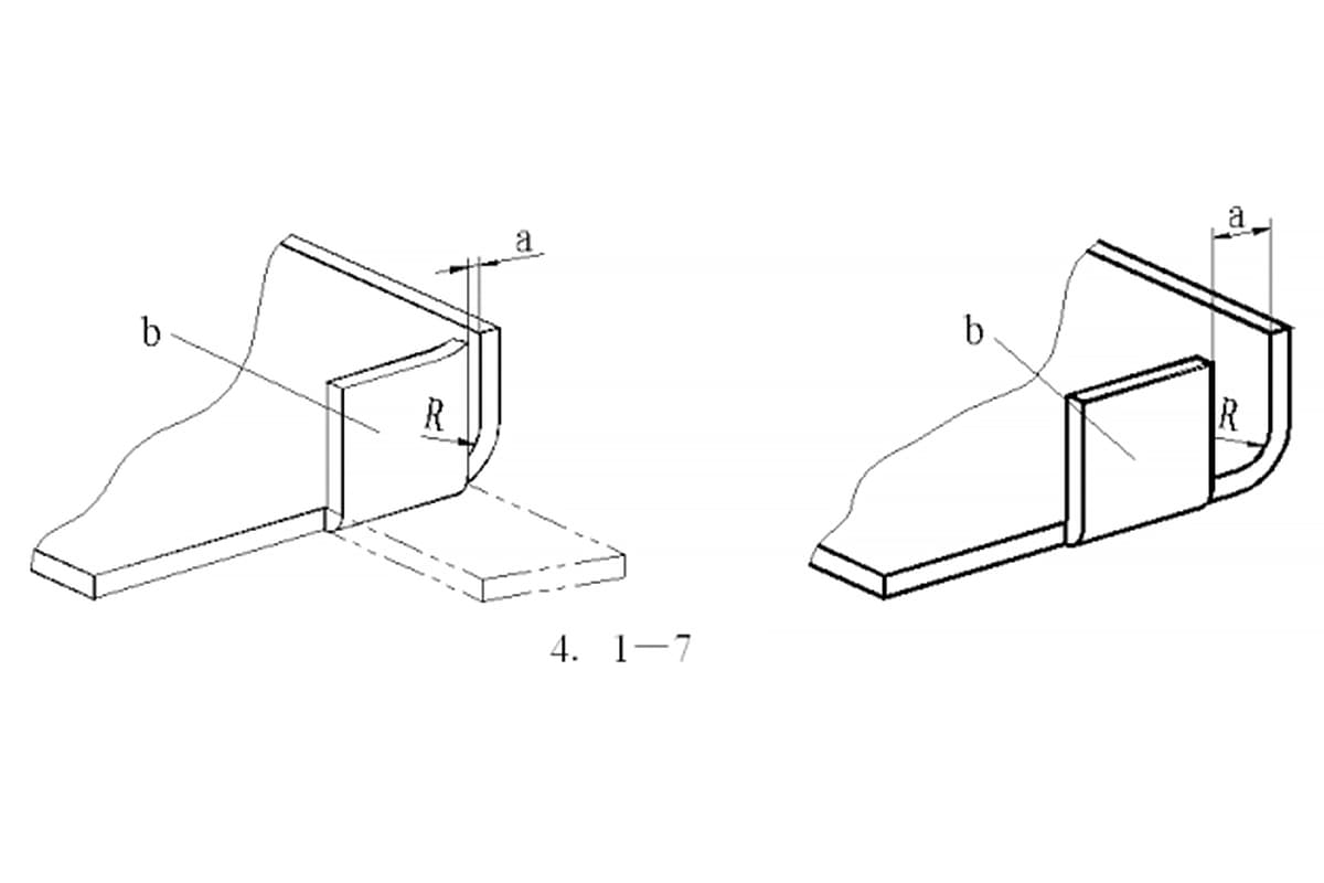
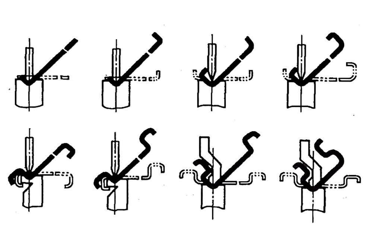
In order to achieve the production processing of bent parts with different bending center angles, there are generally two forms of press brake bending, as shown in Figure 4.
For bent parts with a large structural size, complex cross-sectional shape, or not produced in large quantities, as well as parts produced in single pieces, small batches, and trial production, the method of designing and manufacturing special bending dies is restricted by many unfavorable factors, such as the variety and quantity of parts, the difficulty of die manufacturing, production costs, and delivery deadlines.
Some parts with larger structural sizes and more complex cross-sectional shapes (such as structural parts of chassis and cabinets) are also limited by die structure and enterprise process equipment.
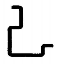
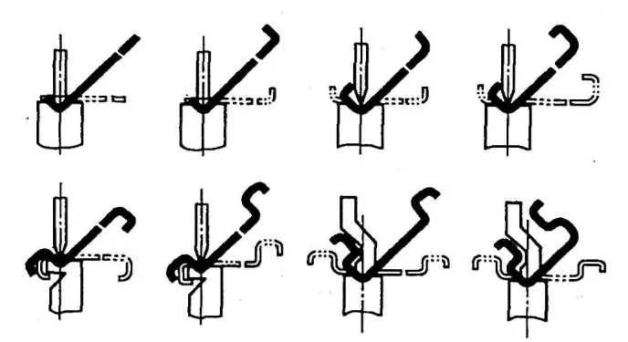
The most effective way to solve these problems is to use the universal bending die for bending. The universal bending die not only can process simple L-shaped, U-shaped, Z-shaped parts, but also can process extremely complex parts by combining convex and concave molds and multiple V-shaped combination bends, as shown in Figures 5 and 6.
(1) Punch (Bending Blade)
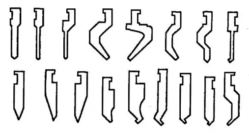
To meet the demand for bending production of various complex bent parts, in recent years, many shapes and specifications of bending blades have been developed, mainly divided into two types: straight-arm and curved-arm bending blades.
They can also be made into integral or combined structures, which can basically meet the bending processing of most complex parts (such as box-shaped, door-shaped, and other special structural parts). Professional die manufacturing factories have standardized and produced the series of bending blades. The common shapes of bending blades are shown in Figure 7.
During processing, the bending blade is chosen based on the shape and size of the bent parts. Usually, sheet metal processing businesses have a large reserve of bending blade shapes and specifications, especially businesses with a high degree of professional specialization in sheet metal production. In order to meet the bending requirements of various complex bent parts, it is necessary to customize many shapes and specifications of bending blades.
(2) Universal Punch
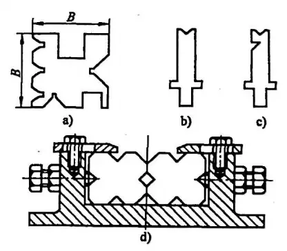
Figure 8 shows the commonly used concave mold cross-sectional shapes for the press brake. The universal concave mold (see Figure 8a) is machined on four sides to bend common sheet metal thicknesses and parts of different shapes and sizes. The groove is selected for bending processing according to the material thickness, shape, and size of the bent parts. Figures 8b and 8c show common concave mold face shapes, which can be made into integral or combined structures (see Figure 8d). They are mainly used for the bending processing of complex parts (such as box-shaped, door-shaped, and other special structural parts).
