Metal sheets are bent and formed using a plate bending machine. The workpiece is placed on the machine and the lifting lever is used to lift the brake block, which allows the workpiece to be positioned. The brake block is then lowered onto the workpiece, and the bending lever is pressed to bend the metal sheet.
The minimum bending radius is determined by the ductility and thickness of the metal being formed. For aluminum sheet metal, the bending radius should be greater than the thickness of the plate.
Due to elasticity, the bending angle of the metal is slightly greater than the required angle.
The bending of metal sheets is typically carried out in a metal processing workshop. Metal sheet processing involves a series of techniques, such as bending, riveting, and welding of metal materials.
The common problems that occur during this process and their corresponding solutions are discussed below.

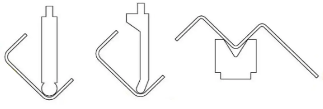
1. Challenges in Bending Groove-Type and Multi-Bend Workpieces
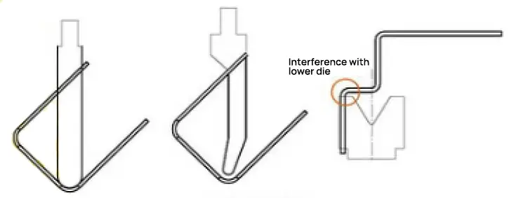
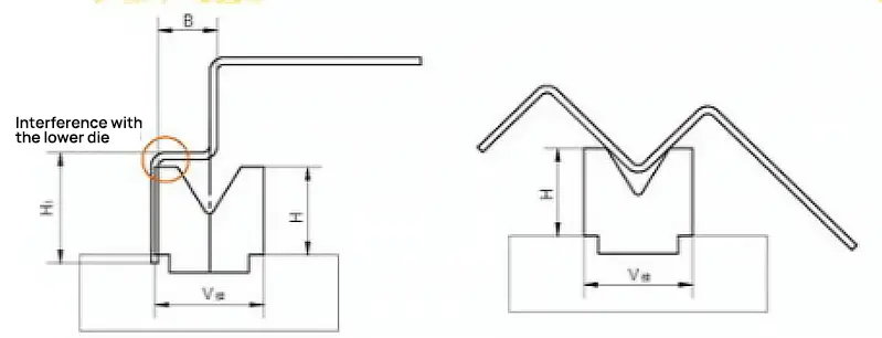
During the bending process of these workpieces, the groove width is larger than the leg height, leading to interference between one end of the workpiece and the upper die or the slider on the press brake. This makes it impossible to guarantee the dimensions of the workpiece, as shown in Figure 2.
Predicting Interference in Sheet Metal Bending
When dealing with high-leg precision sheet metal parts, determining whether bending can be completed requires multiple calculations, with corresponding dimensions indicated in Figure 3.
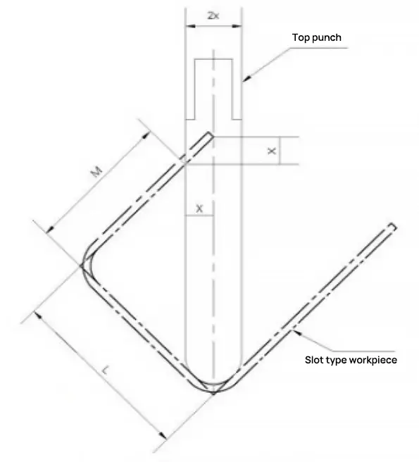
If L-M<1.5x, the workpiece can be bent without interference. If L-M>1.5x, the workpiece cannot be bent as it would cause interference.
Solutions to Interference Problems
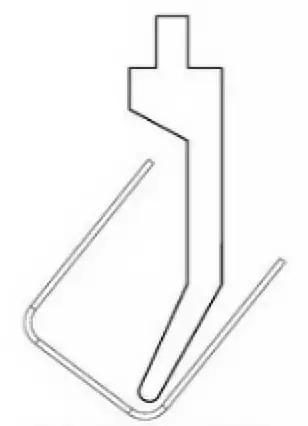
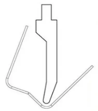
(1) If a groove-type workpiece experiences bending interference, a goose-neck upper die can be selected for bending. This avoids interference between the bending edge of the workpiece and the press brake or upper die, ensuring the bending dimensions of the workpiece, as shown in Figure 4.
(2) If a groove-type workpiece experiences bending interference and there are no suitable goose-neck upper dies available, a reverse pre-bend can be performed in the middle of the bend without affecting usage requirements, as shown in Figure 5. By artificially increasing the bending angle, the workpiece can be bent normally. Then, a flat tire die can be used to spot press the pre-bend area to ensure product quality requirements are met.
(3) When bending multi-bend workpieces, if H1>H or B<V/2, interference can occur between the workpiece and the lower die opening and workbench. The choice of lower die and bending sequence becomes very important, and the following methods can be used:
① Select a high-dimension lower die with H>H1 to ensure normal bending of the workpiece;
② Select a lower die opening with B>V/2 to ensure normal bending of the workpiece;
③ If there is no high-dimension lower die, change the bending sequence. Pre-deform the middle bend to a certain angle, then bend at the short side, form the third bend, and finally repress the middle bend to the required size and angle, ensuring the workpiece’s process size, as shown in Figure 6.
2. Bend Cracking
(1) Analysis of Causes
Bend cracks often occur on the tensile surface of sheet metal parts during bending, damaging the mechanical properties of the workpiece and failing to meet usage requirements, leading to scrapping of the workpiece and economic loss. The main reasons are:
① The sheet metal has a special crystal structure and rolling grain direction, and bending parallel to the grain direction can easily cause fracture;
② The chosen bending radius R is too small;
③ The R angle of the lower die’s V-shaped groove is small;
④ The material’s performance is poor.
(2) Preventive Measures
① When cutting, rotate the sheet metal to cut in the direction perpendicular to the bending (i.e., the material’s bending direction is perpendicular to the grain);
② Increase the upper die R angle;
③ Use a lower die with a large R angle for processing;
④ Choose high-performance materials.
3. The bending edge is not straight and the size is unstable.
Cause Analysis:
- no line pressing or pre-bending.
- inadequate material pressure
- dissymmetric convex-concave die fillet and uneven bending pressure
- low height
Solutions
- design line pressing or pre-bending techniques
- increase jacking force
- even clearance in the convex-concave die and polish fillet
- make the height larger or equal to the minimum size
4. The workpiece is scraped after bending.
Cause Analysis:
- unsmooth material surface
- too small convex die bending radius
- too small bending clearance
Solutions
- improve the smoothness of concave die
- increase convex die bending radius
- adjust bending clearance
5. There are cracks at bending angles
Cause Analysis:
- too small bending radius
- material grain parallel to the bending line
- burr of workblank extending outward
- poor remoldability of metal
Solutions
- increase the bending radius of the convex die
- change blanking layout
- making burrs at the workpiece’s inner fillet
- annealing or using soft material
6. Bending causes hole deformation
Cause Analysis:
When the elastic bending is used to positioning the hole, the outside of the bending arm is pulled by friction on the surface of the concave mold and the outer surface of the workpiece, making the positioning hole deformed.
Solutions
- employing shape bending
- increase coverboard pressure
- add pitting plaid to coverboard to increase friction so as to prevent the workpiece from sliding when bending
7. The bending surface is thinner
Cause Analysis:
- too small convex-concave die fillet
- too small convex-concave die clearance
Solutions
- increase the radius of convex-concave die fillet
- adjust the convex-concave die clearance
8. The workpiece surface is bulging or uneven
Cause Analysis:
Under the tension in the circumferential direction, the outer surface of the material shrinks while the inner surface extends during bending, and forming bulging in the bending direction.
Solutions
- provide adequate pressure to convex-concave die at the final stamping stage
- make concave round angle radius equal to that of the workpiece’s excircle
- optimize techniques
9. The concave part is uneven at the bottom
Cause Analysis:
- uneven material
- small contact area between coverboard and material or inadequate jacking force
- no material support device in concave die
Solutions
- leveling materials
- adjust material support device and increase jacking force
- increase or correct material support device
- increase the shaping processes
10. The axis of holes on two sides are misaligned after bending
Cause Analysis:
The material rebound changes the bending angle, making the central line misaligned.
Solutions
- increase correction process
- improve bending model structure to reduce material rebound
11. The precise hole position cannot be guaranteed after bending
Cause Analysis:
- incorrect unfolding sizes
- material springback
- unstable positioning
Solutions
- calculate the work blank size accurately
- increase correction process or improve bending die structure
- change processing methods or improve positioning
12. The bending line is not parallel to the two-hole center
Cause Analysis:
When the bending height is less than the minimum bending height, the bending part occurs expansion.
Solutions
- increase the height of the workpiece to be bent
- improve bending techniques
13. Deformation occurs in terms of width after bending (the bending part occurs bow deflection in width)
Cause Analysis:
The inconsistent depth and shrinkage in the width of the workpiece cause torsion and deflection.
Solutions
- increase bending pressure
- increase correction process
- ensure a certain angle between materials and bending direction
14. Workpiece with incision occur downward deflection
Cause Analysis:
The incision makes the two straight edges open to the left and right side, forming deflection at the bottom.
Solutions
- improve the workpiece structure
- increase processing allowance at incisions to connect incisions and then cut off the process after bending
15. Slip material during processing
Cause Analysis:
When selecting the bending die, a V-groove width of 4 to 6 times the material thickness (T) is typically chosen. However, if the size of the bend is less than half the width of the selected V-groove, slippage can occur.
Problem: The V-groove selected is too large.
Solutions:
- Centerline deviation method (eccentric machining). When the size of the material to be bent is less than half of 4 to 6 times T, make up as much as possible.
- Padding processing
- Bend with a small V-groove and press with a large V-groove.
- Select a smaller V-groove.
16. The internal bending width is narrower than that of the standard mold
Cause Analysis:
The standard width of the lower die of the bending machine must be at least 10mm. Therefore, the material being bent must be less than 10mm in thickness. If the bend is a 90 degree angle, its length must not be less than √2 (L + V / 2) + T.
To avoid displacement of the mold and any resulting scrap or safety accidents, the mold must be securely fixed on the mold base, with the exception of any upward degree of freedom.
Solutions:
- Increase the size of the bend by negotiating with the customer and making the inner bend wider.
- Special processing of the mold.
- Use grinding tools, though this will increase processing costs.
17. The hole is too close to the bending line. Bending will make the hole pull and turn the material
Cause Analysis:
Suppose the distance of the hole from the bend line is L. If L is less than (4 to 6) times the plate thickness T divided by 2, the material will experience pull-through. This is because during the bending process, tensile force deforms the material, causing pull-through and distortion.
The minimum value of L for different plate thicknesses, based on the standard mold’s groove width, is as follows:
Solutions:
- Increase the size of the bend and trim the hem after forming.
- Expand the hole to the bend line, but only if it does not affect the appearance or function and the customer agrees.
- Use secant or crimping processing.
- Eccentrically process the mold.
- Modify the hole size.
18. The distance L between the drawn edge and the bending line is small, and the drawn edge place is deformed after bending
Cause Analysis:
When L is less than (4 to 6) times the plate thickness T divided by 2, the material will experience deformation during the bending process due to contact between the material and the lower mold.
Solutions:
- Use secant or crimping processing.
- Modify the material size.
- Employ special mold processing.
- Eccentrically process the mold.
19. The long flattening side rises after flattening
Cause Analysis:
The long flattening edge may not adhere tightly during the flattening process, causing it to rise at the ends. This issue is largely dependent on the flattening position, so it is important to pay close attention to the flattening position.
Solutions:
- First bend the upward angle (as shown in the diagram) before bending the dead edge, and then flatten it.
- Flatten in multiple steps.
- Press the end first to bend the dead side down.
- Flatten the root part.
Precautions:
The quality of the flattening process is dependent on the operator’s skills, so it is important to pay close attention to the actual situation during flattening.
20. Large-height draw bridge is easy to break
Cause Analysis:
The material is severely stretched and fractured due to the high height of the draw bridge. Other causes may include:
- Insufficient sharpening or dull special mold corners.
- Poor material toughness or a narrow draw bridge.
Solutions:
- Lengthen the process hole on one side of the fracture.
- Increase the width of the draw bridge.
- Repair the special mold R angle and increase the arc transition.
- Add lubricant to the draw bridge. Note that this method will make the surface of the workpiece dirty and cannot be used for AL parts, etc.
21. During special mold processing, the processing size will change
Cause Analysis:
The workpiece is displaced forward during processing due to a forward pressing force, causing an increase in the small angle L of the front portion.
Solutions:
- Remove any shadows in the picture and try to make it up as much as possible.
- Replace worn self-positioning parts of the mold with back-initiating structures for better positioning.
22. The overall size of the blanking (referring to the expansion) is too small or too large, which is not consistent with the round surface
Cause Analysis:
- Project deployment error.
- Incorrect feeding size.
Solutions:
- Calculate the deviation assigned to each bend based on the total deviation and the number of bends in the deviation direction.
- If the calculated distribution tolerance is within the tolerance range, the workpiece is considered acceptable.
- If the size is too large, use a small V-groove.
- If the size is too small, use a large V-groove.
23. Spalling or loose of the draw-hole after riveting and cause deformation
Cause Analysis:
- Spalling occurs due to a small R angle of the draw-hole or excessive burr on the flange.
- The riveting is loose because the draw holes are not properly aligned.
- Deformation is caused by misaligned holes or incorrect riveting method.
Solutions:
- Use a center punch with a larger R angle and pay attention to the burrs around the draw hole when flanging.
- Increase the pressure, deepen the broaching, and use a center punch with a larger R angle.
- Address the root cause of the misaligned holes and incorrect riveting method.
24. The riveting of the stud is skew or the workpiece is deformed after riveting
Cause Analysis:
- The workpiece is not flattened during processing.
- Uneven force or excessive pressure is applied to the lower surface of the workpiece.
Solutions:
- Flatten the workpiece when pressing the stud.
- Use a support frame.
- Readjust the pressure.
- Increase the stress range on the lower surface and reduce the force range on the upper surface.
25. The two sides are not parallel after offset bending
Cause Analysis:
- The mold is not calibrated correctly.
- The upper and lower die gaskets are not adjusted properly.
- The upper and lower die faces are not identical.
Solutions:
- Recalibrate the mold.
- Adjust the gaskets by increasing or decreasing them.
- Use eccentric processing for the mold.
- Ensure that the upper and lower mold have the same surface.
26. The product surface crease is too deep
Cause Analysis:
- Small V-groove in the lower die.
- Small R angle of the V-groove in the lower die.
- The material is too soft.
Solutions:
- Use a large V-groove for processing.
- Use a mold with a large R angle.
- Use padding bending (with metal or casting polyurethane).
27. The area near the bend deformed after bending
Cause Analysis:
The machine runs too fast during the bending process, causing the upward bending speed during the workpiece deformation to be greater than the speed at which the operator is holding the workpiece by hand.
Solutions:
- Reduce the machine’s running speed.
- Increase the operator’s hand-holding speed.
28. AL parts are prone to cracks when bending
The AL material is prone to breaking along parallel lines during bending due to its special crystal structure.
Solutions:
- When blanking, rotate the AL material so that the bending direction is perpendicular to the texture, then cut.
- Increase the R angle of the upper die.
Related reading: 12 Solutions for Sheet Metal Bending Problems


In the first passage, you write “brake black” in the third line. Maybe it is a small error.
thanks, it has been revised.
I wanted to thank you for explaining some solutions to some sheet metal bending problems. I didn’t know that a scraped workpiece could be fixed by improving the smoothness of concave die. I wouldn’t mind learning how this could be done or how to determine how much smoothness is needed.
We will keep updating the post, so stay turned.
If lh cylinder of 250 ton bending is not working then whats a problem in that cylinder?
Pls refer to this article about press brake troubleshooting:
http://www.machinemfg.com/press-brake-bending-problems-and-solutions/
What is bending clearance? Please explain it deeply…
I have worked in sheet metal fabrication for the past 31 years. Honestly I don’t know where you come up with your list of 12 common bending problems, but I must tell you that you have completely missed the number 1 bending error. It is “parts bent backwards”. If “parts bent backwards” is not your number 1 problem, please explain what you did to drive it further down your list to a point that it doesn’t make your top 12.
Anybody have comments for this?