Imagine turning a flat sheet of metal into a complex, three-dimensional part with precision and efficiency. The art and science of sheet metal fabrication involve a series of meticulous processes, from designing and cutting to bending and welding. This article unpacks the top ten technological processes, guiding you through each step to enhance your understanding and proficiency. Discover how these methods transform raw metal into essential components, and learn the techniques that can boost both productivity and quality in your projects.
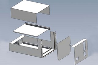
The sheet metal technology process may vary, but it typically does not include more than the ten processes listed below.
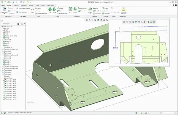
Design and draw drawings of sheet metal parts
Also known as orthographic projection or multiview drawing, its purpose is to accurately represent the three-dimensional structure of sheet metal parts through a set of two-dimensional drawings. Typically, this includes three principal views:
These views are precisely aligned and provide a complete description of the part’s geometry, including its shape, size, and features. For sheet metal parts, special attention is given to:
The drawing should also include:
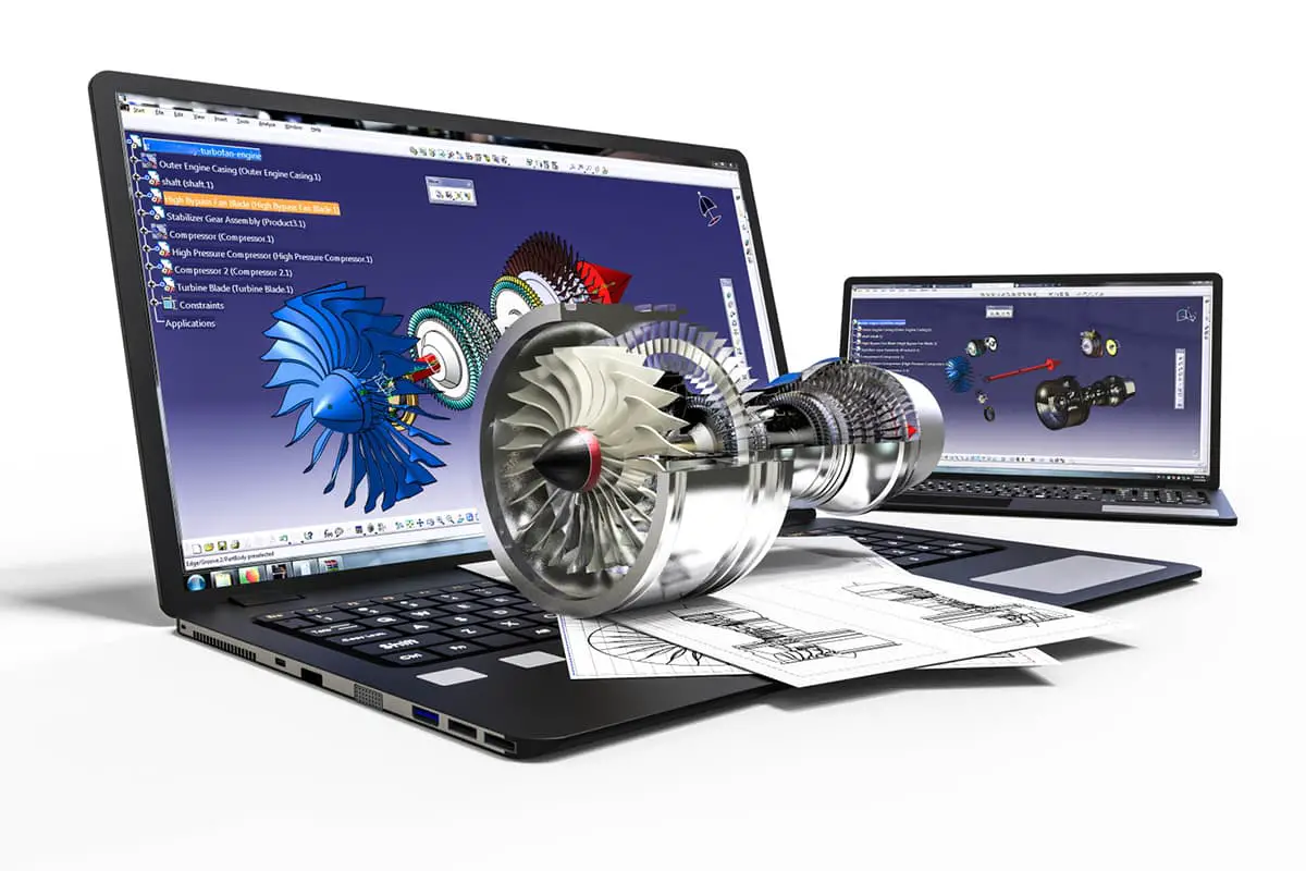
Designers often use CAD software to create these drawings, which allows for easy modification and the generation of 3D models. These detailed drawings are crucial for accurate fabrication, quality control, and communication between design and manufacturing teams in sheet metal work.
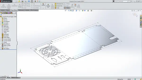
Draw the expansion diagram
The process of drawing an expansion diagram involves transforming complex three-dimensional structures into flattened two-dimensional representations. This technique is crucial in sheet metal fabrication, allowing manufacturers to visualize and plan the precise cuts and bends needed to create the final product. The expansion diagram serves as a blueprint for the unfolded shape of the part, encompassing all surfaces and features in a single plane.
Key steps in creating an expansion diagram include:
Advanced CAD software often automates much of this process, but understanding the underlying principles is essential for optimizing designs and troubleshooting complex parts. Accurate expansion diagrams are fundamental to precision manufacturing, ensuring that the flat blank will form the intended 3D shape when fabricated.
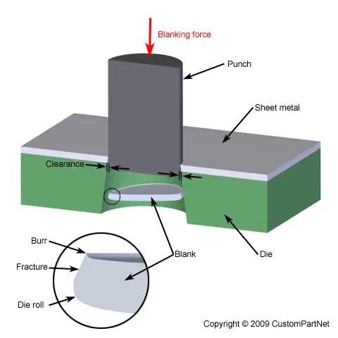
There are several advanced methods for blanking in metal fabrication, each with specific advantages:
A. Shearing Machine Blanking: This method utilizes a cutting machine to produce the required width and length from an expanded metal sheet. For more complex shapes requiring holes or notched corners, a punching machine with specialized dies can be integrated into the process. This method is versatile and cost-effective for simple shapes and medium production runs.
B. Progressive Die Blanking: In this high-efficiency process, parts are formed through a series of stamping operations in a single press setup. The workpiece moves through multiple stations, each performing a specific operation (e.g., piercing, forming, trimming). This method offers significant advantages in terms of speed, efficiency, and cost reduction, making it ideal for high-volume production of complex parts.
C. CNC Blanking: This computer-controlled method begins with CAD/CAM programming to create a digital representation of the expanded part. The program is then translated into machine-readable code for the CNC punch press. The machine precisely punches out the structural shape from flat stock according to the programmed sequence. CNC blanking offers high precision, flexibility for design changes, and is particularly suited for small to medium batch sizes or prototyping.
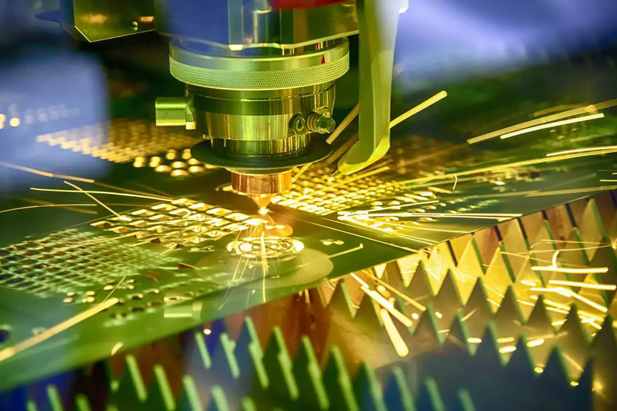
D. Laser Cutting Blanking: This non-contact method employs a high-powered laser beam to cut the structural shape from flat metal sheets. Laser cutting excels in producing intricate designs with tight tolerances and minimal material waste. It’s particularly effective for thin to medium-thickness materials and offers the advantage of no tool wear. The process is highly automated, allowing for quick changeovers between different part designs.
Each blanking method has its optimal applications based on factors such as material properties, part complexity, production volume, and required tolerances. The choice of method often involves a balance between initial tooling costs, production speed, and final part quality.
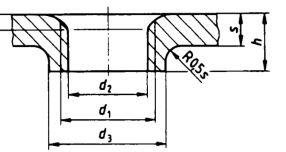
Flange tapping, also known as extruded tapping or flange forming, is a precision metal fabrication process that involves creating an extruded flange around a pre-existing hole and then tapping it to form internal threads. This technique significantly enhances the structural integrity of the threaded connection and provides superior resistance to loosening in thin sheet metal applications.
The process begins with punching or drilling a pilot hole in the sheet metal. Then, a specialized tool is used to extrude the material around the hole, forming a raised collar or flange. This extruded material increases the effective thickness of the sheet at the connection point, allowing for more thread engagement and improved load distribution.
For thin sheet metal (typically less than 2.0mm), flange tapping offers several advantages:
For thicker plates, such as those 2.0mm or 2.5mm and above, direct tapping without flange formation is often sufficient. The inherent material thickness provides adequate thread engagement and strength for most applications.
When selecting between flange tapping and direct tapping, consider factors such as material thickness, load requirements, vibration exposure, and sealing needs. Proper tool selection and process parameters are crucial for achieving optimal results in either method.
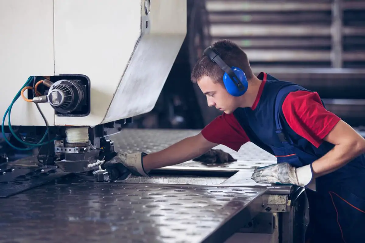
The punching process encompasses a variety of precision operations, each designed to achieve specific metal forming outcomes. These operations include hole punching, corner notching, blanking, embossing, nibbling, and drawing, among others.
Each operation demands a specialized tool or die to ensure optimal results and maintain tight tolerances. For example, embossing requires a male and female die set to create raised or recessed designs, while nibbling utilizes a series of overlapping punches to create complex contours or large openings.
The selection of appropriate tooling is critical to the success of each operation. Factors such as material properties, sheet thickness, desired features, and production volume influence the choice of punch and die configuration. Advanced punch presses often feature turret systems that can hold multiple tools, allowing for rapid changeovers and complex, multi-step fabrication processes.
Modern CNC-controlled punching machines enhance precision and productivity by automating tool selection and positioning. This technology enables the seamless integration of various punching operations within a single setup, significantly reducing production time and improving consistency across parts.
To optimize punching processes, manufacturers often employ nesting software to maximize material utilization and minimize waste. Additionally, the use of lubrication systems and high-quality tool steels can extend die life and improve part quality, especially when working with high-strength or abrasive materials.
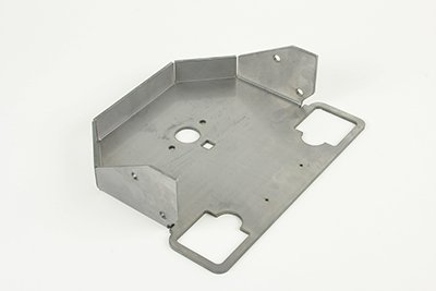

The factory extensively utilizes pressure riveting techniques for fastening sheet metal components, primarily employing riveting studs, nuts, and screws. This precise joining method ensures robust and reliable connections in various metal fabrication applications.
The riveting process is predominantly executed using advanced punching machines or high-capacity hydraulic riveting systems. These sophisticated machines offer precise control over the riveting force and depth, guaranteeing consistent joint quality across large production runs. The choice between punching and hydraulic riveting machines depends on factors such as material thickness, required joint strength, production volume, and specific product requirements.
For optimal results, the riveting process is carefully calibrated to match the specific characteristics of the sheet metal being joined, including material type, thickness, and surface finish. This tailored approach minimizes the risk of material distortion or damage while maximizing joint integrity and longevity.
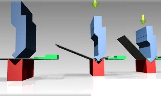
Bending is a fundamental sheet metal forming process that transforms 2D flat parts into 3D components with precise angles and contours. This operation is primarily executed using a press brake in conjunction with specialized bending dies. The process involves applying controlled force to deform the metal along a linear axis, creating permanent bends without compromising material integrity.
Modern press brakes offer various bending techniques, including air bending, bottoming, and coining, each suited to specific material properties and desired outcomes. The selection of appropriate tooling, such as V-dies and punch tips, is crucial for achieving optimal bend quality and accuracy.
A critical aspect of efficient bending is the establishment of a strategic folding sequence. The governing principle is to prioritize bends that do not interfere with subsequent operations, followed by those that may cause tool interference. This approach minimizes the risk of collisions between the workpiece and tooling, ensures dimensional accuracy, and optimizes production efficiency.
Factors such as material thickness, grain direction, bend radius, and springback must be carefully considered when designing and executing bending operations. Advanced press brakes now incorporate CNC systems and offline programming capabilities, allowing for complex multi-bend parts to be produced with high precision and repeatability.
For a comprehensive understanding of press brake technology, including machine specifications, tooling options, and advanced bending techniques, refer to “The Ultimate Guide to Press Brake“. This resource provides in-depth insights into optimizing your bending processes for enhanced productivity and quality.
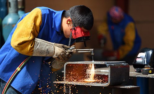
Welding is a critical fabrication process that involves joining multiple components or reinforcing a single part through fusion to enhance structural integrity and achieve desired manufacturing outcomes.
Various welding techniques are employed in modern metalworking, each suited to specific materials and applications:
The selection of an appropriate welding method depends on various factors, including material properties, joint design, production volume, and quality requirements. For instance, GMAW is typically preferred for welding iron or steel plates due to its high deposition rate and good penetration. Conversely, GTAW is the method of choice for aluminum welding, offering superior control and weld quality, particularly for thinner sections.
Robotic welding systems have revolutionized large-scale metalworking operations. By automating the welding process, they significantly reduce labor requirements, improve consistency, and enhance overall productivity. These systems are particularly advantageous for repetitive tasks, long weld seams, and applications requiring high precision, such as in the manufacture of large cabinets or structural components.
Advancements in welding technology, such as adaptive control systems and real-time monitoring, continue to improve weld quality, reduce defects, and optimize process parameters. This ongoing evolution in welding techniques and equipment plays a crucial role in meeting the ever-increasing demands of modern manufacturing for efficiency, quality, and cost-effectiveness.
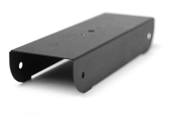
Surface treatment encompasses a range of advanced techniques designed to enhance the properties and performance of metal components. These processes include phosphate conversion coating, colored zinc electroplating, chromate conversion coating, powder coating, and anodizing, among others.
Phosphate conversion coating is primarily applied to cold-rolled steel and electrogalvanized sheets. This process creates a micro-crystalline phosphate layer that significantly improves corrosion resistance, paint adhesion, and lubricity. The resulting phosphate film serves as an excellent base for subsequent painting or coating operations.
Colored zinc electroplating is a versatile surface treatment often employed for cold-rolled steel sheets. This process not only provides a decorative finish but also offers superior corrosion protection. The color options range from bright to pastel shades, allowing for both functional and aesthetic customization.
Chromate conversion coating and anodizing are frequently utilized for treating aluminum plates and profiles. Chromate conversion produces a thin, protective film that enhances corrosion resistance and paint adhesion. Anodizing, an electrolytic process, creates a durable, porous oxide layer that can be dyed in various colors and provides excellent wear and corrosion resistance.
Powder coating, a dry finishing process, is increasingly popular for its durability and environmental benefits. It involves electrostatically charging dry powder particles and spraying them onto the metal surface, followed by curing in an oven to create a uniform, high-quality finish.
The selection of a specific surface treatment is determined by various factors, including the base material, intended application, environmental exposure, aesthetic requirements, and cost considerations. Tailoring the surface treatment to the customer’s precise specifications ensures optimal performance and longevity of the metal components.
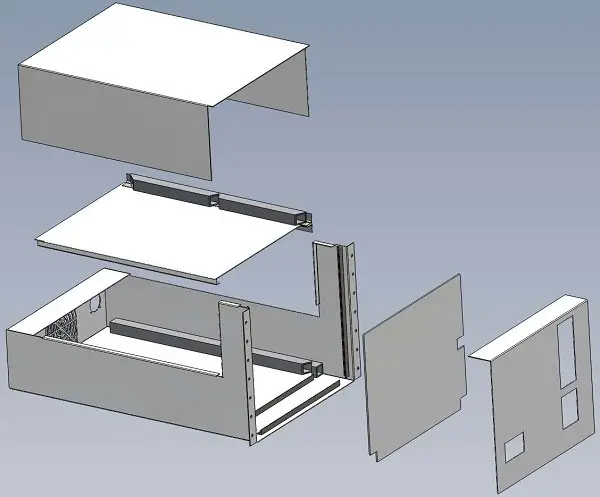
Assembly is the critical final stage in manufacturing where multiple components are precisely combined to create a finished product. This process requires meticulous attention to detail and a comprehensive understanding of the product’s design and functionality.
A crucial factor in assembly is the protection of components from damage, particularly scratches. Even minor surface imperfections can compromise the product’s integrity, aesthetics, and performance. Implementing proper handling techniques and using protective materials (e.g., soft cloths, temporary coatings, or custom fixtures) are essential to maintain component quality throughout the assembly process.
The importance of scratch prevention cannot be overstated. If parts become unusable due to scratches or other damage, it necessitates rework, leading to significant consequences:
To mitigate these risks, manufacturers must implement robust quality assurance protocols and train assembly personnel in proper handling techniques. This may include:
By prioritizing component protection and integrating it into standard operating procedures, manufacturers can ensure higher product quality, reduce waste, and optimize production efficiency in the assembly stage.

