How does one ensure that sheet metal parts remain firmly connected without welding or screws? This article explores the riveting process, a critical technique in metal fabrication. You’ll learn about the various types of riveting, key precautions, and how to select the appropriate method for your specific needs. Whether you’re dealing with high-pressure requirements or specialized materials, this guide will provide essential insights to enhance the quality and efficiency of your riveting operations.
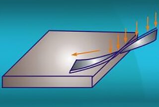
Sheet metal parts and products are ubiquitous in both industry and daily life, and are widely recognized as one of the fundamental processing categories.
There are four primary sheet metal processing techniques: punching (shearing), folding (rolling), welding, and surface treatment.
In addition to these techniques, riveting technology is also an important method for connecting sheet metal parts.
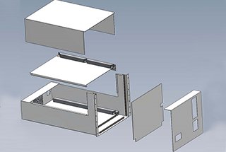
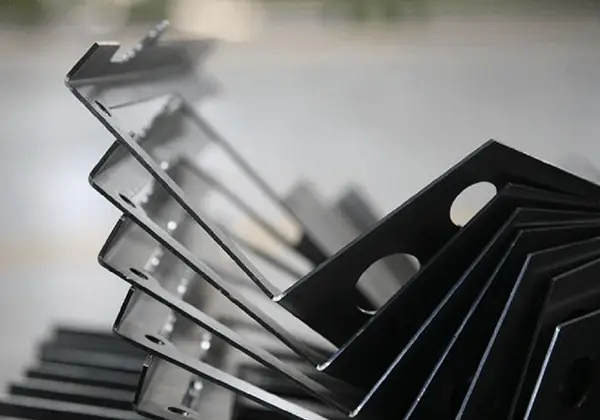
Riveting involves using specialized equipment and tooling dies to apply force and compress or embed the riveted parts into the workpiece, ensuring that it remains secure and vertical. This process is illustrated in Figure 1.
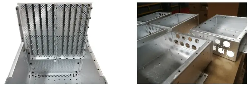
Fig. 1 Riveted parts of communication equipment
Common riveting techniques include radial riveting and rotary riveting. In this section, we will discuss some important precautions and key points for the production control of radial riveting, which is commonly used in our factory (see Fig. 2).
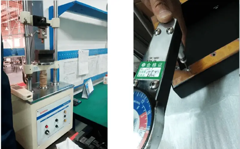
Fig. 2 Radial riveting equipment and riveting process
(1) The size of the riveting bottom hole should be designed in strict accordance with the manuals of general or special equipment, standard parts, and should comprehensively consider the material, thickness, model, and strength requirements of the base material and riveting parts.
When machining the bottom hole, blanking or laser cutting is commonly used as a pre-processing method. Table 1 compares the two processes of die blanking and laser cutting.
Table 1 Two processes of die blanking and laser cutting
| Pre-process | Die blanking | Laser cutting |
| Bottom hole size | Good accuracy and consistency | The stability of the hole shape and size is slightly poor |
| Substrate change | The blanking tear band is not smooth | There are hardness changes on and around the hole wall |
| Other attention | The burr surface is convex and the smooth surface collapses | Lead, splash and other foreign matters |
For parts with high-quality requirements and large production batches, it is recommended to customize the die, consider the riveting direction, and prioritize the stamping process to create the riveting bottom hole.
If the previous process involves bending, it is necessary to consider whether the riveting bottom hole is located on the bending line (upper).
In this situation, a pre-processing step involves creating a small hole, followed by bending and stretching, and then creating the small hole to the designed size through drilling or reaming.
(2) When selecting the riveting process, it is essential to consider the throat depth of the actual equipment, the form of upper and lower supports, and other conditions to confirm whether it can be carried out successfully.
Furthermore, it is generally recommended to arrange the riveting process after the surface treatment process (such as electroplating, chemical oxidation, spraying, etc.).
If riveting is carried out before surface treatment, it can often lead to issues listed in Table 2.
Table 2 possible problems caused by different surface treatments
| Process | May cause problems |
| Carbon steel electroplating | The zinc layer of stainless steel rivets is peeling, the thread is not smooth, the electroplating solution is stored, and the corrosion is slow under working conditions |
| Aluminum chemical oxidation | The hole diameter of the bottom hole becomes larger, the rivets become loose and the strength decreases |
| Surface spraying | Increase the amount of escaping coating, and it is easy to lead to poor threaded rivets |
(3) For certain specialized products, such as base materials with a thickness ≤ 1.5mm or products with high pressure riveting strength requirements, welding reinforcement may be necessary after pressure riveting.
In cases where welding reinforcement is required, it is recommended not to select galvanized parts for pressure riveting, as this can have an adverse impact on the welding reinforcement process.
The general requirements for riveting operations encompass:
In addition to these standard practices, our factory’s production experience has yielded the following operational guidelines:
(1) Operators typically assess rivet integrity through visual inspection, checking for gaps between riveted parts and the substrate, or steps at the riveting position after countersunk riveting. This 100% self-inspection is crucial. Moreover, surface hardness varies among materials, decreasing from galvanized plates to stainless steel and low-carbon steel plates. Consequently, pressure parameters should be pre-adjusted based on the specific riveting materials. For components with potential detachment risks, technical requirements for welding and spot reinforcement should be agreed upon with the client in advance.
(2) Riveting operations must be executed in a single pass to eliminate the need for secondary riveting and minimize repairs of detached parts, particularly for high surface hardness materials. Repeated riveting can damage the clinching teeth and base materials. In cases where repair of original parts is unavoidable, post-riveting welding reinforcement is mandatory.
(3) For post-riveting technical inspection, quality control personnel must possess the capability to perform spot checks on breaking torque and, when feasible, breaking push-off force. First article inspection and technical sampling of the riveting process cannot be substituted by operator self-inspection, making this step indispensable in the quality assurance protocol.
(1) It is important to pay attention to whether the riveting position interferes with adjacent bending edges (lines), outer edges, or weld beads, as this can affect both the quality of the riveting and the appearance of the assembly. Please refer to Table 3 for common riveting interference problems.
Table 3 Common interference problems of riveting
| Type | Example | Proposal |
| Distance from the free edge |
 | L1 value reference manual |
| Distance from bend edge |
 | L1 ≥ bending radius and L1 ≥ riveting head radius of riveter |
| Close to the weld bead | Be sure to check for any interference between the riveting parts and the upper and lower dies. If there is interference, the dies may need to be repaired to prevent any air gaps. |
(2) When there are multiple types of riveting standard parts and similar parts on the same component, it is recommended to avoid operating them all on the same machine to prevent mixing and misuse of the riveting parts. Additionally, when there are many riveting parts of the same specification on a component, the riveting sequence should be standardized to prevent missed rivets.
(3) During the riveting process, if the operator needs to leave their post for any reason, such as for eating or shift handover, the worktable must be cleared to ensure that processed and unprocessed parts are not mixed.
(4) If there is a hole near the riveting position, it is important to confirm whether the hole is extruded or deformed after riveting. For pressure-riveted screws and nuts, a thread gauge should be used to detect the through end and stop end after pressure riveting.
Riveting refers to the process of using rivets to connect two or more workpieces, typically sheet metal pieces or components. Riveting can be classified into rivet riveting, pull riveting, and core striking riveting.
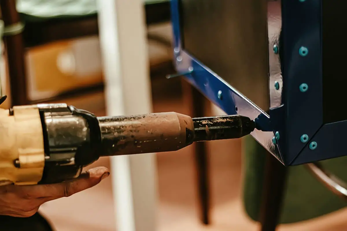
Riveting is a fundamental mechanical fastening technique widely used in metal fabrication and assembly processes. The key component in this method is the rivet, a deformable fastener that creates a permanent connection between two or more parts. Rivets come in various types, each designed for specific applications and material thicknesses:
The riveting process is categorized based on the rivet diameter and application requirements:
The standard riveting process follows these key steps:
For detailed specifications on rivet parameters and riveting requirements, consult industry-standard mechanical design handbooks, which provide comprehensive guidelines for various applications and materials.
Pull riveting is a single-sided fastening technique that utilizes pull rivets to join two or more components with aligned holes. The process involves using a specialized pull rivet gun to draw the mandrel (pull rod) until it fractures, causing the rivet sleeve to expand and form a permanent, non-detachable connection.
1) Pull rivets, also known as blind rivets or pop rivets, are engineered for applications where access is limited to one side of the workpiece. These fasteners require specialized tools such as manual, electric, or pneumatic pull rivet guns for installation. Pull rivets excel in scenarios where conventional riveting methods (requiring access to both sides) are impractical or impossible.
Due to their versatility and ease of use, pull rivets find extensive applications across various industries, including:
The most commonly used types of pull rivets include:
A) Open-type dome head pull rivets: Offer a balance of strength and aesthetics for general-purpose applications.
B) Countersunk pull rivets: Provide a flush finish, ideal for surfaces requiring smooth riveting and aerodynamic profiles.
C) Sealed pull rivets: Feature enhanced load-bearing capacity and sealing properties, suitable for high-stress environments or applications requiring water/air-tight connections.
When selecting and installing pull rivets, consider the following best practices:
A) For flat head (countersunk) pull rivets:
B) For dome head pull rivets:
2) For detailed pull riveting parameters, including rivet sizes, grip ranges, and recommended hole diameters, refer to Table 9-17 in the technical specifications section.
Table 9-17 Pull Riveting Parameters
| Rivet Type | Nominal Rivet Diameter (mm) | Steel Plate Rivet Hole Diameter (mm) | Length (mm) | Riveted Steel Plate Thickness /mm | |
| Umbrella-shaped | Flathead | ||||
| Aluminum Rivet | 2.4 | 2.5 | 5.7 | 1.0-3.2 | 1.6~3.2 |
| 7.3 | 3.2-4.8 | 3.2-4.8 | |||
| 8.9 | 4.8-6.4 | 4.8~6.4 | |||
| 3.0 | 3.1 | 6.3 | 1.0~3.2 | 1.6~3.2 | |
| 8.0 | 3.2~4.8 | 3.2-4.8 | |||
| 9.8 | 4.8~6.4 | 4.8~6.4 | |||
| 3.2 | 3.3 | 6.3 | 1.6-3.2 | 1.6-3.2 | |
| 8.0 | 3.2-4.8 | 3.2-4.8 | |||
| 9.8 | 4.8~6.4 | 4.8-6.4 | |||
| 4.0 | 4.1 | 6.9 | 1.6~3.2 | 1.6-3.2 | |
| 8.6 | 3.2-4.8 | 3.2-4.8 | |||
| 10.4 | 4.8-6.4 | 4.8-6.4 | |||
| 4.8 | 4.9 | 7.5 | 1.6-3.2 | 2.3~3.2 | |
| 9.3 | 3.2-4.8 | 3.2-4.8 | |||
| 11.1 | 4.8~6.4 | 4.8~6.4 | |||
| Steel Rivet | 3.2 | 3.3 | 6.4 | 1.0~3.2 | |
| 9.5 | 3.2~6.4 | ||||
| 4.0 | 4.1 | 10.2 | 3.2~6.4 | ||
| 4.8 | 4.9 | 10.8 | 3.2-6.4 | ||
Note:
1. Generally, the through-hole of a part is 0.1~0.2mm larger than the nominal diameter of the blind rivet.
2. Blind rivets can be blackened or otherwise treated to meet product requirements, allowing them to match the color of the workpiece.
3. The center distance of the blind rivet hole from the edge of the base plate should be more than twice the diameter of the blind rivet hole. At this distance, the riveting strength is optimal. If the distance is less, the strength greatly decreases.
Strike-core rivets, also known as drive-pin rivets, are an innovative type of single-sided fastener designed for efficient and versatile assembly applications. During installation, the rivet head is struck with a hammer or pneumatic tool, causing the core pin to expand and lock into place, resulting in a flush finish with the rivet head’s end face. This unique mechanism ensures a secure and aesthetically pleasing connection.
These rivets offer exceptional convenience in assembly processes, particularly in scenarios where traditional two-sided riveting is impractical or blind rivets are unsuitable due to equipment limitations. Their design allows for rapid installation without specialized tools, making them ideal for field repairs, maintenance operations, and assembly lines with space constraints.
Strike-core rivets are available in various configurations to suit different application requirements:
Material options typically include aluminum, steel, and stainless steel, allowing for compatibility with a wide range of base materials and environmental conditions. The selection of rivet material and coating should consider factors such as corrosion resistance, structural integrity, and galvanic compatibility with the joined materials.
When specifying strike-core rivets, engineers should consider factors such as grip range, shear and tensile strength requirements, and the substrate material properties to ensure optimal performance and longevity of the fastened joint.
Drawn arc stud welding is an advanced and efficient method for joining metal components, particularly effective for connecting sheet metal parts. This process is widely utilized in various industries, especially for attaching studs to coated steel plates, stainless steel sheets, and other metal surfaces.
In this technique, a specially designed stud is positioned against the workpiece. When the welding process is initiated, an electric arc is drawn between the stud and the base material. This arc melts both the end of the stud and a small area of the base metal. As the molten pool is formed, the stud is then rapidly plunged into the liquefied metal, creating a full-fusion weld upon solidification.
The process typically involves the following steps:
Drawn arc stud welding offers several advantages:
This method is particularly beneficial for applications requiring high-strength fastening points on sheet metal, such as in automotive body construction, shipbuilding, and structural steel fabrication.
The process of drawn arc stud welding is illustrated in Figure 9-7, which demonstrates the key stages of the welding sequence.

(1) Advantages of Pull-hole Riveting
The flange and countersink hole combination inherently possess a positioning function. The riveting strength is also high due to the usage of a riveting die, resulting in a higher production efficiency.
(2) Disadvantages of Pull-hole Riveting
It’s a one-time connection and can’t be disassembled.
1) Principle of shell matching:
H=t+t’+(0.3~0.4)
When the thickness ‘t’ is greater than or equal to 0.8mm, the flanging hole wall thickness is set at 0.4t.
When ‘t’ is less than 0.8mm, the flanging hole wall thickness is typically set at 0.3mm.
The height ‘h’ is generally chosen to be 0.46±0.12mm.
For the parameters of the drawn hole riveting, refer to Table 9-18.
Table 9-18 presents the drawn hole riveting parameters (in mm).
| Parameter Number | Material Thickness t /mm | Bending Height H /mm | Flange Outer Diameter D/mm | |||||||||||
| 3.0 | 3.8 | 4.0 | 4.8 | 5.0 | 6.0 | |||||||||
| Corresponding to the inner diameter ‘d’ of the straight hole and the bottom hole ‘do‘ of the pre-flanged edge. | ||||||||||||||
| d | d0 | d | d0 | d | d0 | d | d0 | d | d0 | d | d0 | |||
| 1 | 0.5 | 1.2 | 2.4 | 1.5 | 3.2 | 2.4 | 3.4 | 2.6 | 4.2 | 3.4 | ||||
| 2 | 0.8 | 2.0 | 2.3 | 0.7 | 3.1 | 1.8 | 3.3 | 2.1 | 4.1 | 2.9 | 4.3 | 3.2 | ||
| 3 | 1.0 | 2.4 | 3.2 | 1.8 | 4.0 | 2.7 | 4.2 | 2.9 | 5.2 | 4.0 | ||||
| 4 | 1.2 | 2.7 | 3.0 | 1.2 | 3.8 | 2.3 | 4.0 | 2.5 | 5.0 | 3.6 | ||||
| 5 | 1.5 | 3.2 | 2.8 | 1.0 | 3.6 | 1.7 | 3.8 | 2.0 | 4.8 | 3.2 | ||||
The above content summarizes the experience gained from handling common issues and operations during the riveting process in sheet metal production and processing.
It is worth noting that some factories have partially achieved the automation of automatic feeding mechanisms and riveting. This automation solution is beneficial in avoiding human errors to a great extent. However, the degree of automation implemented varies due to factors such as cost, technology, product variety, type, and batch size.
Whether you opt for manual operation, semi-automatic or fully automatic production scheme, the information presented above can be useful in your production process.

