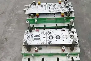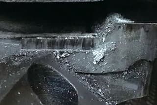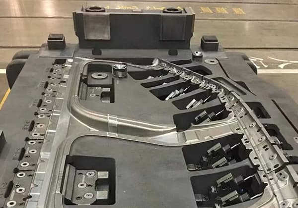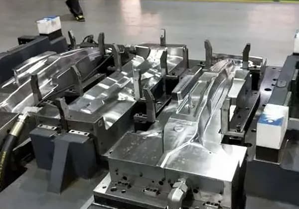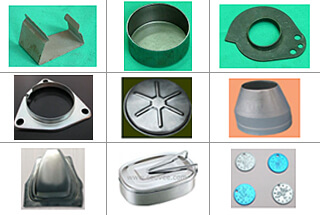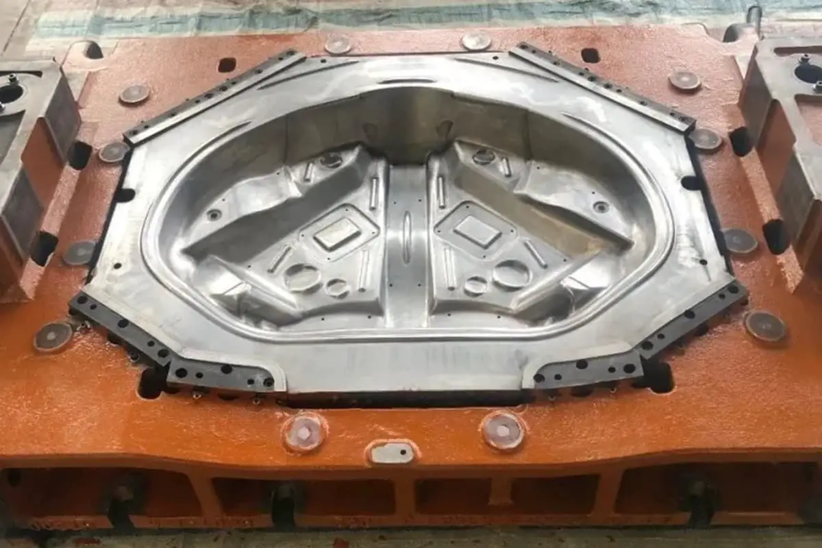
Have you ever wondered what makes a punch design critical for stamping dies? This article breaks down the essential principles behind punch structures, from circular and non-circular shapes to the methods of fixing punches. By exploring these concepts, you’ll understand how to optimize mold quality and performance, ensuring your stamping processes run smoothly. Dive in to uncover practical insights and precise guidelines that will elevate your engineering projects to the next level.
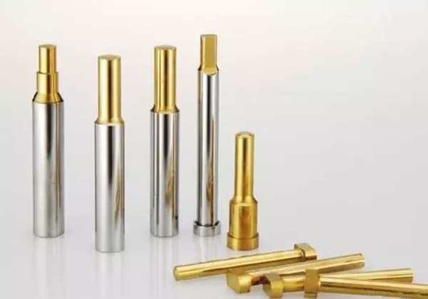
The quality of the mold product is directly affected by the quality of the punch. So, how important is the punch? Let us share it with you below.
Punch Structure Theory
There are various forms of punches in the mold. The structure of non-circular section punches should be determined according to the process of the strip and the state of the mold products.
As for circular section punches, there are corresponding national standards.
The most common circular punch structures are as follows:
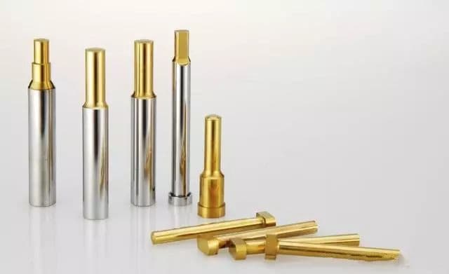
We can understand circular punches as A-punches and T-punches. Punches are divided into first-order, second-order, and third-order. This is their difference.
A-punches are used in smaller punch positions, while T-punches are used in larger punch positions.
In another situation, when the thickness of the stamping material and the aperture are similar to the structure of the small hole punch, a protective cover structure is used to improve its longitudinal bending resistance, as shown in the figure.

The figure below shows the structural style used to ensure convenient installation and self-strength when there is space in the punching or when the mold parts are large.

We need to use technology to shape non-circular punches, but we can understand them as two categories: circular and square. When the workpiece is circular, we can make the fixed part of the punch cylindrical. Similarly, we can make the fixed part of the punch square.
Usually, using saddle nails to deal with the rotation persuasion of the convex machine can reduce the complexity of making the punch, as shown in the figure below.
However, when using cylindrical fixed non-cylindrical punches, attention should be paid to the shift of the punch.

Generally, we use a clamping plate to fix the punch and use clearance fit to deal with the gap between the punch and the clamping plate.
The gap can be appropriately adjusted based on the thickness of the material and the precision of the mold, generally at 0.01mm on one side.
In the case of a larger diameter, the punch can be made in the form of an assembly step. Multi-head punching molds and other small and medium-sized convex molds are usually fixed in the form of rivets, especially when the distance between them is relatively small.
If the multi-head punching mold is designed with a stepped structure, they will interfere with each other, and the rivet structure will be more compact in this case.

For the fixation of large stamped workpieces, it is a good idea to fix the upper die base and the punch, and to make the punch a detachable fitting. For some punches that are easily worn and some small punches, the solution is to use a replaceable punch fixing form.
This structural form has the advantages of reducing mold repair time, faster replacement, and no need to disassemble the upper die as a whole. There is also a method of fixing with adhesive that is not commonly used now, which will not be described in detail. See the figure below for details:

The length of the punch is generally determined by the structure of the mold and theoretically determined by the thickness of the upper mold plate.

Generally, the shorter the time to meet the requirements of structure and use, the better. The length of the punch can be calculated by the following formula:
L = h1 + h2 + h3 + (10-20) (mm)
Where h1 is the thickness of the guide ruler (mm), h2 is the thickness of the discharge plate (mm), h3 is the thickness of the convex mold fixing plate (mm).
The length of the punch is mostly determined by the structure of the punching mold.
In concept, it is determined by the thickness of the upper mold plate. Generally, the shorter the better when the structure and use requirements are reasonable. The above formula can be used to calculate the length of the convex mold.
The formula of 10-20 millimeters includes the depth of the punch entry, the punch repair amount, and the distance between the discharge plate of the punch and the clamping plate of the punch in the closed state.
The length of the punch should be modified according to the structure and requirements of the punching mold. It is only necessary to verify when the punch section is very small and the thickness and hardness of the punched material are large.
Otherwise, in general situations, it is not necessary to calculate the hardness of the punch.
Based on the analysis above, it is clear that punches are important. Therefore, designers should pay more attention to them in their designs.

