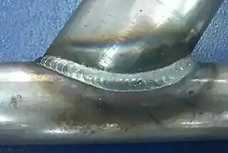
Welding steel structures demands precision and expertise. What common pitfalls could compromise your welding projects? In this article, we explore essential tips for successful steel structure welding. Learn how to handle welding stress, reduce deformations, and understand the best welding methods for different scenarios. By mastering these techniques, you can ensure your welds are strong, reliable, and meet the highest standards. Discover the key strategies to elevate your welding skills and enhance the integrity of your steel structures.
Advantages of welding connection:
Simple structure, no weakening of component section, simple processing, various welding methods, automatic operation, saving steel, high efficiency, large stiffness, good integrity, and good sealing performance.
Disadvantages of welding connection:
The heat-affected area of steel undergoes changes in its metallographic structure, causing local materials to become brittle.
Welding results in residual stress and deformation, which decrease the bearing capacity of compression members.
Welded structures are highly susceptible to cracking. If local cracks occur, they are prone to extensive propagation, and low-temperature cold brittleness is more pronounced.
Steel’s weldability refers to the ease with which materials can be welded while meeting the required structural performance under appropriate design and working conditions. The weldability of steel is often influenced by its chemical composition, rolling method, and plate thickness.
To evaluate the impact of chemical composition on weldability, it is generally expressed as carbon equivalent (Ceq). The weldability of steel is better when the Ceq is smaller because it indicates a lower hardening tendency of the material. Conversely, when the Ceq is larger, the weldability of steel is worse due to its greater hardening tendency.
The carbon equivalent value of Ceq (percentage) can be calculated using the following formula:

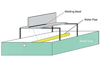
The welding process of a steel structure involves uneven heating and cooling. During welding, the temperature of the weld and its surrounding area is very high, while the metal at a distance remains unheated. As a result, the expansion and contraction of the main metal is uneven.
Upon cooling, the weld seam will experience varying degrees of shrinkage and internal stress (both longitudinal and transverse), leading to different deformations in the welding structure.
To reduce welding stress and deformation, two aspects can be addressed: design and processing technology.
Design measures:
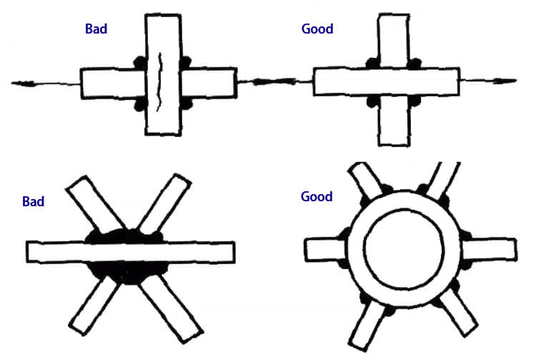
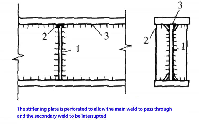
The weld position should be reasonably arranged.
The selection of weld size should be made based on reasonability.
The number of welds should be kept to a minimum and should not be overly concentrated. Additionally, it’s essential to avoid creating a three-dimensional crisscross of welds.
It’s important to avoid shrinkage stress in the thickness direction of the base metal as much as possible.
Process measures:
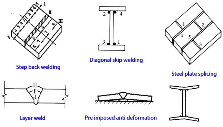
Arrange welding sequence reasonably;
Adopt reverse deformation;
Preheating before welding and tempering after welding.
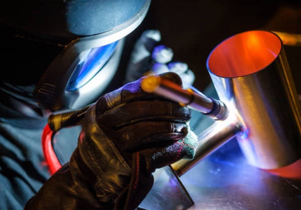
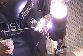
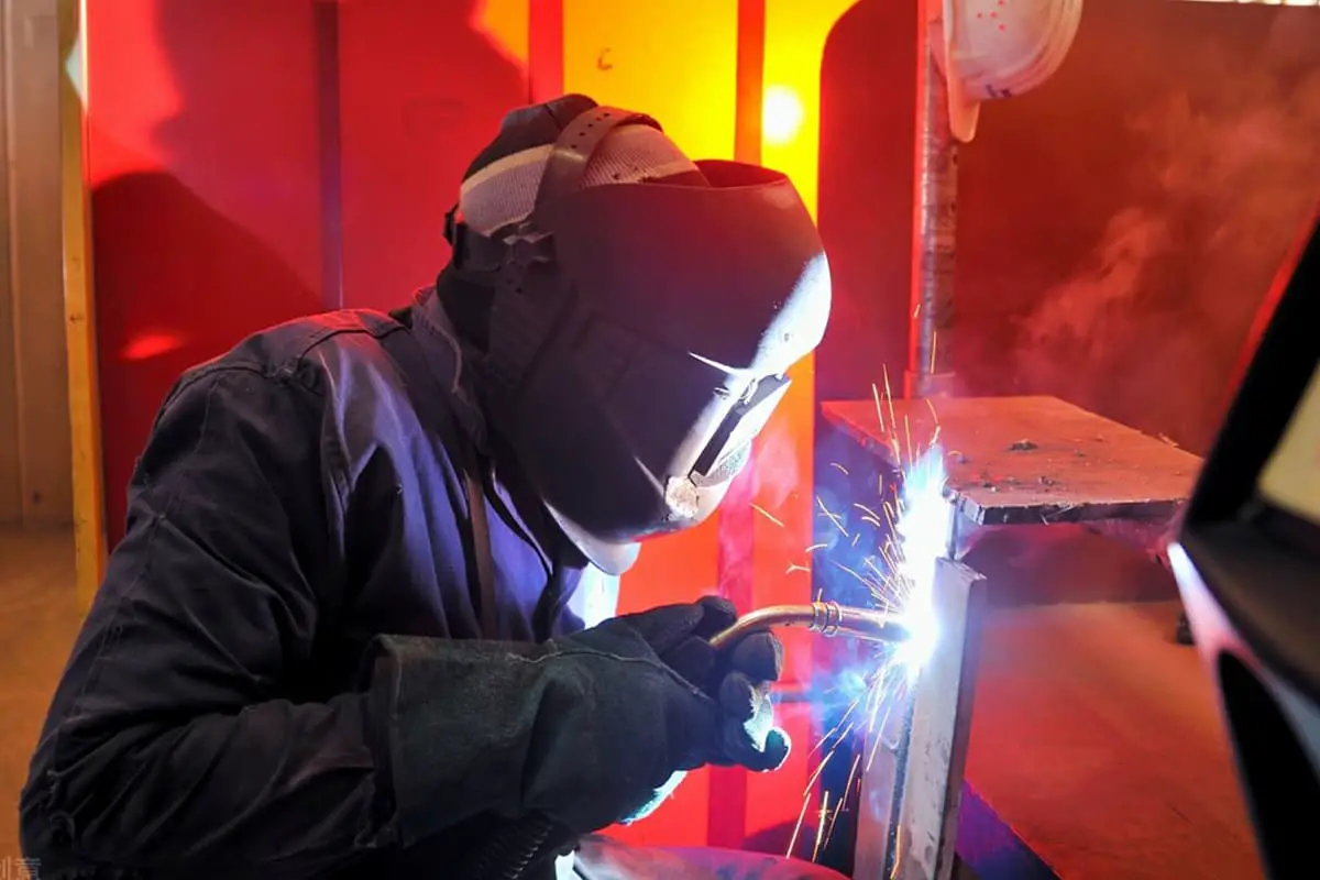
The commonly used welding methods for steel structures include manual arc welding, automatic (or semi-automatic) submerged arc welding and gas shielded welding.
Related reading: Manual Arc Welding vs CO2 Gas Shielded Welding
Manual arc welding:
After being electrified, an electric arc is generated to melt the welding wire in the electrode and drop it into the small groove molten pool blown by the electric arc on the weldment.
The slag and gas formed by the electrode coating cover the molten pool to prevent the air from contacting the molten liquid metal and the formation of brittle and crack prone compounds.

Submerged arc welding:
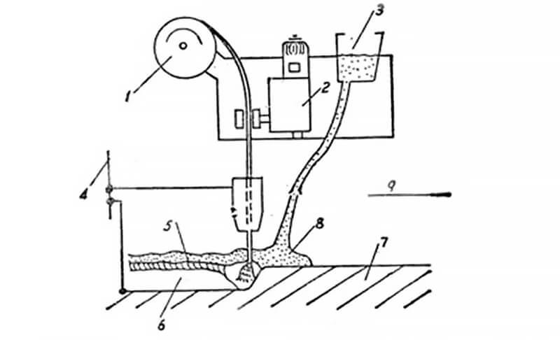
This welding method utilizes an arc that burns beneath a layer of flux. Unlike traditional methods, the welding wire is not coated with any additional material. Instead, the welding end is covered by granular flux, which flows automatically from the flux leakage head.
As a result, the arc is completely buried in the flux, which causes the heat to concentrate and penetrate deeply. This makes it an ideal method for welding thick plates with high productivity while maintaining good welding quality and minimal deformation of the weldment.
Gas shielded welding:
This is an arc fusion welding method that employs carbon dioxide or other inert gases as a protective medium. The shielding gas forms a local protective layer around the arc, which helps prevent the invasion of harmful gases and ensures the stability of the welding process.
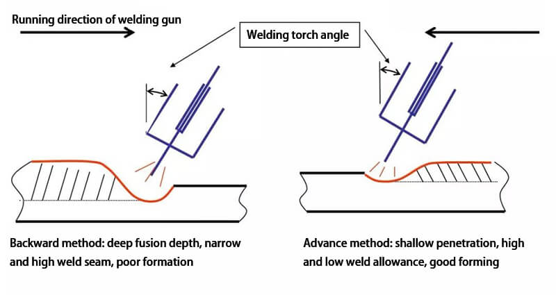
Compared to manual arc welding, this method produces welds with higher strength, excellent plasticity, and corrosion resistance. It is suitable for all position welding, including both forward and backward methods.
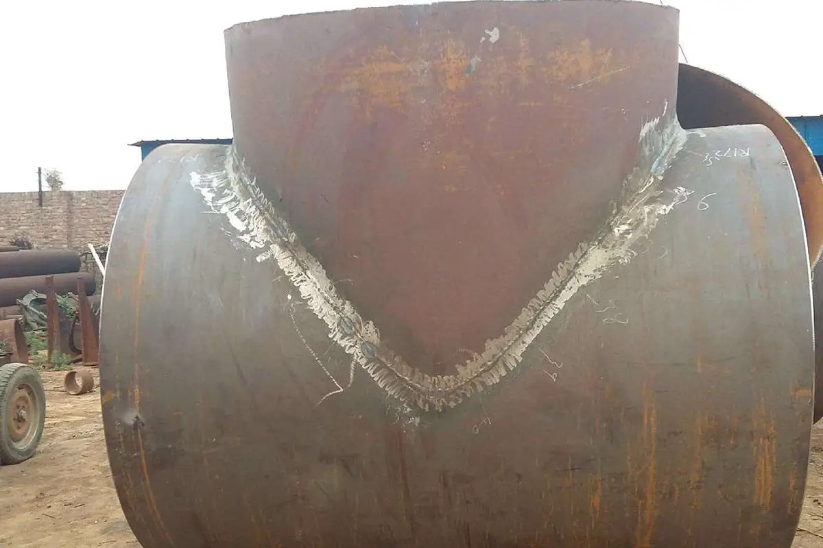
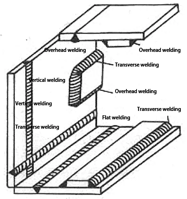
Common welding positions, joint forms, groove forms, weld types and pipe structure node form codes are shown as follows:
| Code | Welding position |
| F | downward welding |
| H | Horizontal position welding |
| V | Vertical welding |
| O | Overhead position welding |
Related reading: What Does 1G, 2G, 3G, 4G, 5G and 6G Mean in Welding?
Joint type and groove shape code
| Type of joint | Groove shape | ||||
| Code | Name | Code | Name | ||
| I | I-groove | ||||
| Plate joint | B | Butt joint | V | V-groove | |
| T | T-joint | X | X-groove | ||
| X | pipe cross | L | Single side V-groove | ||
| C | fillet joint | K | K-groove | ||
| F | Lap joint | U1 | U-groove | ||
| Pipe joint | T | T-joint | J1 | Single side U-groove | |
| K | K-joint | Note: 1. When the thickness of steel plate is ≥ 50mm, U-shaped or J-shaped groove can be used | |||
| Y | Y-joint | ||||
The weld defects are divided into six categories: cracks, cavities, solid inclusions, incomplete fusion, incomplete penetration, and shape defects.
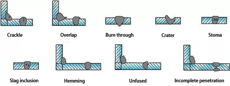
Crackle:
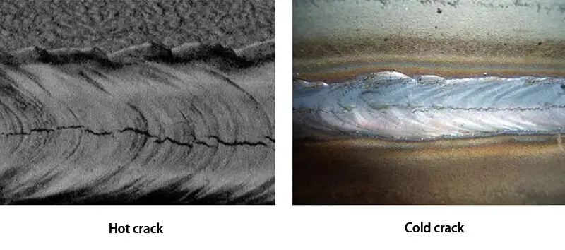
Hot cracks and cold cracks are two common types of welding defects.
Hot cracks are mainly caused by poor crack resistance of the base metal, low-quality welding materials, improper selection of welding process parameters, and excessive welding internal stress.
On the other hand, cold cracks are often the result of an unreasonable design of the welding structure, improper arrangement of welding seams, and inadequate welding process measures, such as lack of preheating before welding and rapid cooling after welding.
To treat these types of cracks, one method is to drill crack stop holes at both ends of the crack or remove the weld metal at the crack for repair welding.
Cavity:
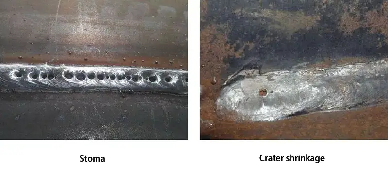
The defects in welding are generally divided into two types: air holes and crater shrinkage.
Air holes are primarily caused by several factors, including serious damage to the electrode coating, failure to bake the electrode and flux, oil stains or rust and oxide on the base metal, insufficient welding current, excessively long arc length, and fast welding speed.
The treatment for air holes is to remove the defective weld metal at the site of the air hole and then perform a repair welding procedure.
Crater shrinkage, on the other hand, is mainly caused by excessive welding current, high welding speed, rapid arc quenching, and insufficient filler metal addition to repeatedly quench the arc.
The treatment for crater shrinkage is to perform a repair welding operation at the location of the crater.
Solid inclusion:
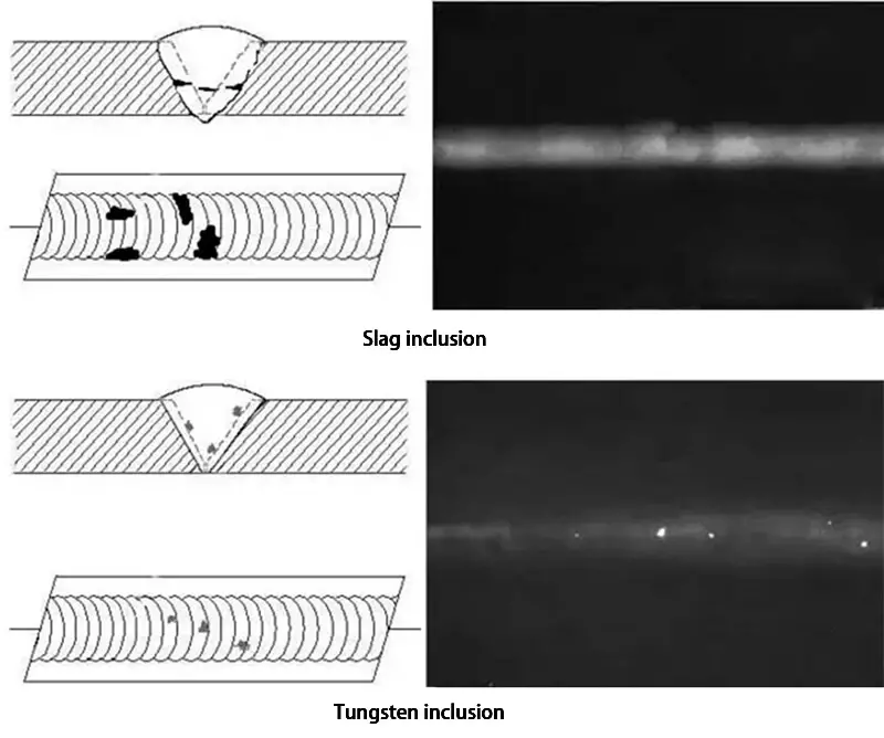
There are two types of defects that can occur during welding: slag inclusion and tungsten inclusion.
The main causes of slag inclusion are the poor quality of welding materials, welding with too low current, welding at too fast of a speed, high slag density that blocks the slag’s floating ability, and the failure to clean up slag during multi-layer welding.
To remedy slag inclusion, the weld metal around the affected area must be removed, and then the welding process can continue.
Tungsten inclusion is typically caused when the tungsten electrode comes into contact with the molten pool metal during argon arc welding.
To repair this defect, the defective metal at the tungsten inclusion must be dug out, and the welding process can then be resumed.
Incomplete fusion and penetration:
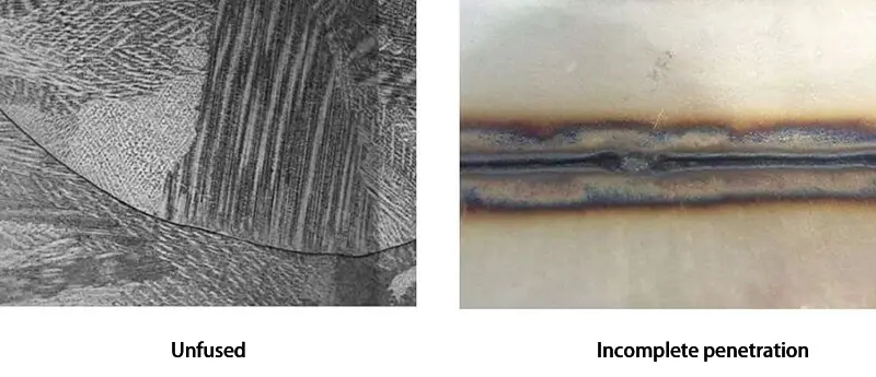
There are several main reasons for incomplete welding, including welding current that is too small, welding speed that is too fast, groove angle gap that is too small, and poor operating technology.
The treatment method for non-fusion is to remove the weld metal at the non-fusion position, and then repair the weld.
To treat incomplete penetration, the method is to repair the incomplete penetration on one side of the structure with good openness directly at the back of the weld.
For important weldments that cannot be repaired directly by welding, the incomplete weld metal must be removed, and the welding must be redone.
Shape defect:
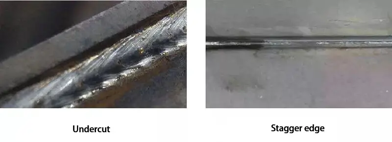
Including undercut, overlap, sagging, root shrinkage, misalignment, angle deviation, weld superelevation, surface irregularity, etc.
For T-shaped, cross-shaped, and corner joints, when the thickness of the flange plate is not less than 20mm, in order to avoid or reduce large welding shrinkage stress in the direction of the base metal plate thickness, the following joint structure design should be adopted:
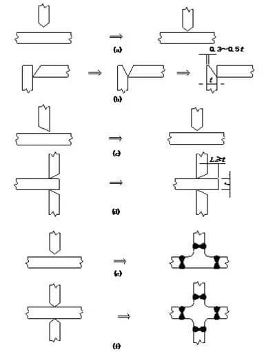
Change the stress direction of the thick plate joint to reduce the stress in the thickness direction;
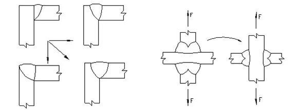
For nodes subject to static load, under the condition of meeting the requirements of joint strength calculation, the fully penetrated groove weld shall be replaced by the partially penetrated butt and fillet weld.

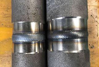
After the completion of welding and weld inspection, the first step of inspection shall be appearance inspection. Visual inspection or magnifying glass should be used to observe for any defects such as undercut, burn through, incomplete penetration, cracks, staggered edges, staying, and to check whether the overall dimensions of the weld meet the requirements.
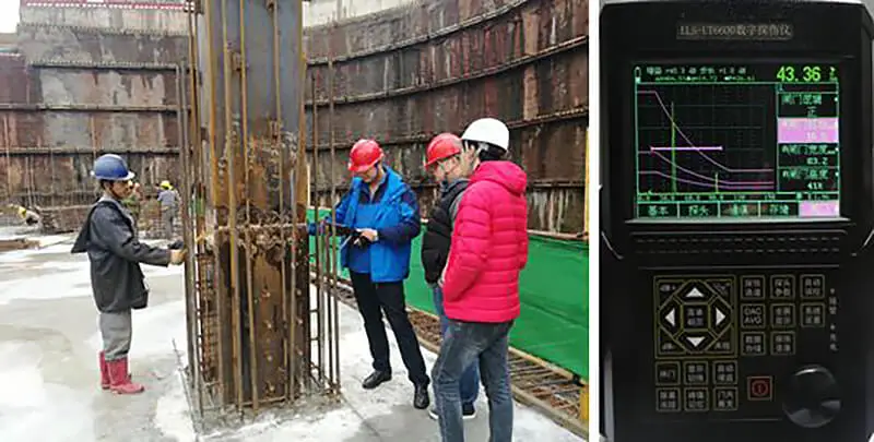
Defects inside the weld are usually detected by ultrasonic waves. This method is based on the principle that ultrasonic waves can spread inside the metal and reflect and refract when encountering the interface of two mediums, which helps in inspecting the flaws inside the weld. The waveform can be used to determine the presence and location of the flaw.
Since there is a reflective surface between the probe and the test piece, during ultrasonic inspection, the coupling agent should be coated on the surface of the weldment. However, the ultrasonic method cannot determine the type and size of the defects.
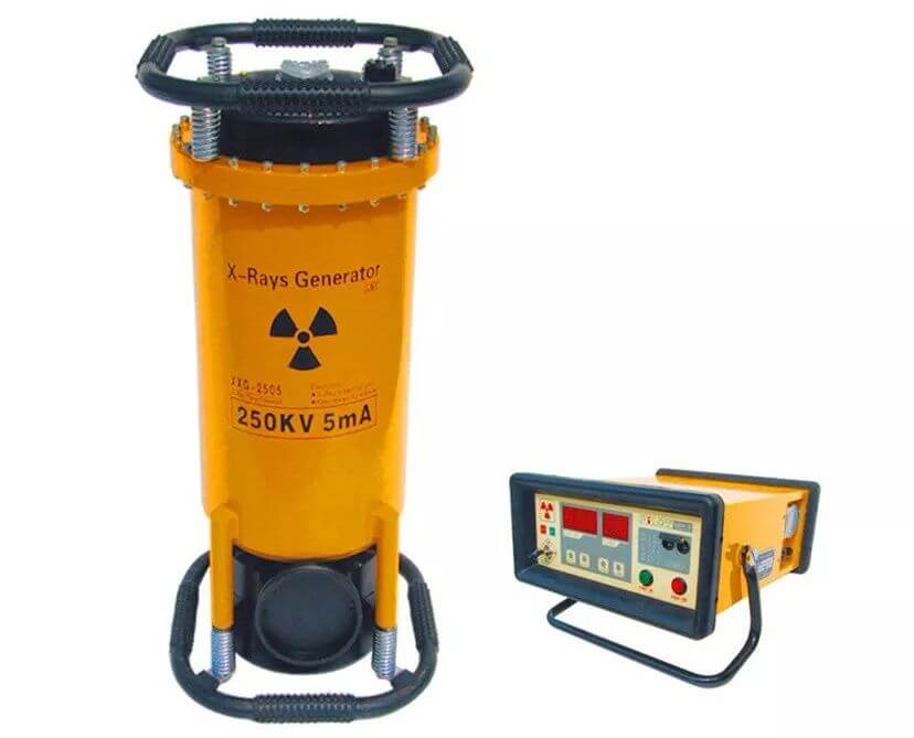
Radiographic inspection is sometimes used in nondestructive testing to detect defects in welds. There are two types of radiographic inspection: X-ray and γ-ray inspection. The principle is that when the ray passes through the inspected weld, any defects will result in less attenuation of the ray passing through that area.
As a result, the negative film on the back of the weld is highly sensitive to light, and black spots or stripes will appear at the location of the defect after the film is washed.
X-ray inspection has a short exposure time, high speed, and strong penetration capacity, but the equipment is complex, costly, and suitable for testing weldments with a thickness of less than 30mm. In contrast, γ-ray inspection equipment is portable, easy to operate, and has strong penetration capacity.
Batch acceptance criteria for welds:
Additional inspection criteria:
Apart from the exemptions listed in the national steel structure welding code, any combination of steel, welding materials, welding methods, joint forms, welding positions, post-welding heat treatment systems, welding process parameters, preheating and post-heating measures, and other parameters used by the construction unit for the first time, shall be subject to welding process assessment before fabricating and installing steel structure members.

