Ever wondered how gears are made? The process involves multiple intricate steps to achieve precision and efficiency. This article breaks down the 11 essential stages of gear processing, from ordinary turning to final measurement. You’ll discover how each step, like gear hobbing, shaping, and honing, contributes to producing high-quality gears. By the end, you’ll understand the critical role of various machining techniques and tools in gear manufacturing. Prepare to delve into the fascinating world of gear production and learn what makes this engineering feat possible.
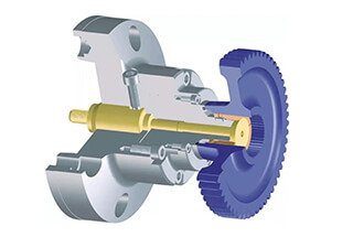
Gear machining is a highly intricate process and requires the use of the right technology to achieve efficient production. Each stage of the production must be precise in terms of dimension.
The gear machining cycle includes:
ordinary turning → gear hobbing → shaping → shaving → hard turning → gear-grinding machining → honing → drilling → bore grinding → welding → measurement
It is crucial to utilize the appropriate clamping system during the gear machining process. In this text, we will introduce the gear clamping system for each step of the process.

During conventional turning, the gear blank is typically secured on a vertical or horizontal turning machine. Automatic clamping fixtures, in most cases, do not necessitate an additional stabilizer on the opposite side of the spindle.


Gear hobbing is an economical cutting process that is commonly used to produce external and cylindrical gears. This process is not only popular in the automotive industry but also in the manufacturing of large industrial transmissions, provided that it is not limited by the outer shape of the workpiece.


Shaping is a gear machining process that is employed primarily when hobbing is not feasible. This method is mainly utilized for internal gears and some external gears that have complex structures.


Shaving is a finishing technique for gears in which the cutting is done using a cutter that resembles the tooth shape of the gear. This process has gained widespread use in the industry due to its high efficiency and cost-effectiveness.


Hard turning enables the replacement of costly grinding procedures. For proper functioning, the various components of the system must be properly connected to the machined part. The selection of the appropriate machine tool, fixture, and cutting tools is critical in determining the success of the hard turning process.

6. Gear-grinding machining

To achieve the level of precision demanded in modern gear production, hard finishing of the tooth flanks is often a necessity. This method is a cost-effective and efficient solution for mass production. On the other hand, grinding offers greater flexibility, especially when adjustable grinding tools are used, similar to individual machining.

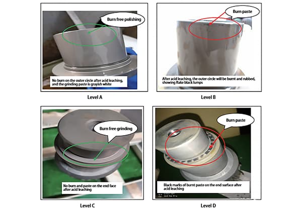
Honing is the final finishing process for hard gears, achieved by using a cutting angle that is not well-defined. This process not only offers cost-efficiency but also results in smooth surfaces with low noise levels in the machined gears. Honing has a low cutting speed, ranging from 0.5 to 10 m/s, compared to grinding, which eliminates the heat-related damage to the gear machining.
Additionally, the internal stresses generated on the machined tooth surface have a positive impact on the equipment’s load capacity.

Examples of honing with flanged fixtures:

Drilling is a rotary cutting technique. The axis of the cutting tool and the center of the drilled hole are aligned in the axial direction, and the feed direction is the same as the cutting tool’s axial direction. The spindle that powers the cutting motion should be aligned with the cutting tool, regardless of the feed motion direction.

Example of drilling with the SG clamping system:

Bore grinding is a machining process that uses a cutting angle that is not well-defined. Compared to other cutting techniques, grinding offers advantages such as high dimensional and form accuracy, high dimensional precision (IT 5-6), and excellent surface accuracy (Rz = 1-3μm) with minimal chatter marks on hard metals.

Example of bore grinding with the film clamping SM system:

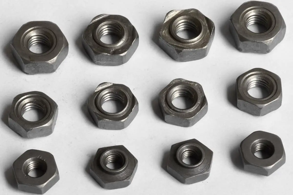
Capacitive discharge welding is a type of resistance welding process. This method involves a rapid increase in current, a brief welding time, and a high welding current. As a result, capacitive discharge welding offers many advantages, including economic and efficient operation, which are particularly relevant due to rising energy costs.

Example of capacitive discharge welding using a welding fixture system:

The testing of gears is comprehensive and must be tailored to the various forms of gears. In the evaluation of gears, the key parameters of the gear are determined by measuring its length, angles, and specific gearing techniques.

Examples of measurements with flanged SP clamping systems:


