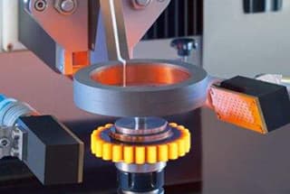
Have you ever considered how gears endure intense pressures without wearing out quickly? Surface hardening is the key! This process involves methods like flame and induction quenching to create a durable outer layer, enhancing both the gear’s fatigue strength and wear resistance. In this article, you’ll discover various surface hardening techniques and their benefits, ensuring your gears perform efficiently and last longer. Dive in to learn how to maximize the lifespan and reliability of your gears through effective surface hardening strategies.
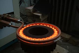
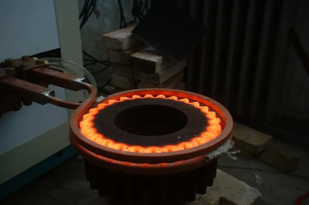
The common surface quenching methods for gears include flame quenching, induction quenching, contact resistance heating quenching, and advanced laser quenching.
By performing surface heating and quenching, a hardening layer can be created on the surface while maintaining the original microstructure and properties of the gear core. This enhances the fatigue strength and wear resistance while preserving the core’s excellent toughness. Additionally, this process is energy-efficient and reduces distortion during gear quenching.
See Table 1.
Table 1 Classification of surface hardening
| Classification | Technology | |
| Rough separation | Subdivision | |
| Heating method for heating | – | Induction quenching, flame quenching, salt bath heating quenching, electrolyte quenching, contact resistance heating quenching, laser quenching, electron beam quenching, ion beam quenching, high-frequency pulse current induction quenching, solar heating quenching, etc. |
| energy density | Lower energy density heating | Induction quenching, flame quenching, salt bath heating quenching, electrolyte quenching, etc. |
| High energy density heating | Laser quenching, electron beam quenching, ion beam quenching, contact resistance heating quenching, solar heating quenching, etc. | |
| energy source | Internal heat source heating | Induction fire, pulse current induction quenching, etc. |
| External heat source heating | Flame quenching, salt bath heating quenching, electrolyte quenching, contact resistance heating quenching, laser quenching, electron beam quenching, ion beam quenching, solar heating quenching, etc. | |
1) See Table 2 for the technical requirements of surface hardened gears.
Table 2 technical requirements for surface hardened gears
| Project | Pinion | Big gear wheel | Instruction |
| Depth of hardened layer / mm | (0.2-0.4)m① | Effective hardened layer depth, as per GB / T5617-2005 | |
| Tooth surface hardness (HRC) | 50~55 | 45~50 or 300~400HW | If the transmission ratio is 1:1, the tooth surface hardness of large and small gears can be equal. |
| Surface organization | Fine needle martensite | Ferrite is not allowed on the teeth | |
| Heart hardness (HBW) | Quenching and tempering:Carbon steel 265 ~ 280Alloy steel 270 ~ 300 | For some gears with low requirements, normalizing can be used as preliminary heat treatment. | |
① m is the gear module (mm).
2) Distribution form, strengthening effect and application range of hardened layer on gear surface

Process method:
Rotary heating quenching method.
Enhancement effect:
The wear resistance of the tooth surface is improved;
The bending fatigue strength has little influence, and the allowable bending stress is lower than the level of the steel after tempering.
| High frequency (including ultra audio frequency) quenching | Medium frequency (2.5KHz, 8kHz) quenching | Flame quenching |
| The diameter of induction processing gear is determined by the equipment power;Gear width 10 ~ 100mm;m≤5mm。 | The diameter of the processing gear is determined by the equipment power, and the gear width is 35 ~ 150mm;Individually up to 400mm;m≤10m | The gear diameter can reach 450mm;Special quenching machine;m ≤ 6mm, m ≤ 12mm in some cases |
Note: m – gear module (mm)

Process method:
Rotary heating quenching method.
Enhancement effect:
The surface wear resistance of the teeth and the bending fatigue strength of the tooth roots are improved. The allowed bending stress is 30% to 50% higher compared to a quenched and tempered state. This process can partially substitute for carburized gears.
| High frequency (including ultra audio frequency) quenching | Medium frequency (2.5KHz, 8kHz) quenching | Flame quenching |
| The diameter of induction processing gear is determined by the equipment power;Gear width 10 ~ 100mm;m≤5mm. | The diameter of the processing gear is determined by the equipment power, and the gear width is 35 ~ 150mm;Individually up to 400mm;m≤10m | The gear diameter can reach 450mm;Special quenching machine;m ≤ 6mm, m ≤ 10mm in some cases |

Process method:
Single tooth continuous heating quenching method.
Enhancement effect:
The wear resistance of the tooth surface is improved, but the bending fatigue strength may be impacted to some extent (generally, the hardening layer ends 2 to 3mm from the tooth root). The allowed bending stress is lower than that of the steel after tempering.
| High frequency (including ultra audio frequency) quenching | Medium frequency (2.5KHz, 8kHz) quenching | Flame quenching |
| Gear diameter is not limited, m ≥ 5mm | Gear diameter is not limited, m ≥ 8mm | Gear diameter is not limited, m ≥ 6mm |

Process method:
Continuous heating and quenching along the tooth groove.
Enhancement effect:
The surface wear resistance of the teeth and the bending fatigue strength of the tooth roots are improved. The allowed bending stress is 30% to 50% higher compared to a quenched and tempered state. This process can partially substitute for carburized gears.
| High frequency (including ultra audio frequency) quenching | Medium frequency (2.5KHz, 8kHz) quenching | Flame quenching |
| Gear diameter is not limited, m ≥ 5mm | Gear diameter is not limited, m ≥ 8mm | Gear diameter is not limited, m ≥ 10mm |
3) Typical machining process of surface hardened gears: blank → normalizing (or annealing) of forging stock → mechanical rough machining → quenching and tempering → mechanical semi finishing (blank making) and gear making → surface quenching → low temperature tempering → mechanical finishing → finished products.

