Ever wondered why your laser-cut metal pieces aren’t as precise as they used to be? This article uncovers the secrets behind laser cutting kerf, exploring how factors like beam quality, material thickness, and cutting speed impact your results. Learn how to maintain top-notch performance and achieve perfect cuts every time!
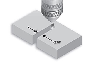
As a common piece of equipment for sheet metal processing, a laser cutting machine plays a vital role.
Efficient and high-precision cutting are deeply ingrained in people’s minds.
However, after long-term use, the equipment’s performance may decline, and even the cutting plate may have large kerfs, which can affect cutting quality.
This issue needs to be resolved promptly. Let’s take a closer look below.
The cutting performance of an optical fiber laser cutting machine decreases due to machine wear and tear after long-term use, as well as due to insufficient maintenance during machine operation.
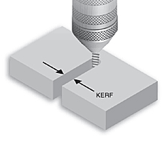
The kerf width in laser cutting varies depending on several factors, including material type, thickness, laser power, and cutting parameters. Different cutting methods and equipment produce varying kerfs and accuracies.
For instance, when cutting a 10mm thick plate:
(1) Fiber laser cutting typically achieves a cutting accuracy of ±0.025mm and a kerf width ranging from 0.2 to 1mm. The precise kerf depends on the laser power, cutting speed, and assist gas used.
(2) Plasma cutting, while less precise, produces a cutting accuracy of approximately ±0.3mm and a kerf width between 0.5 and 1.2mm. This method is often preferred for thicker materials or when speed is prioritized over precision.
(3) Manual oxy-fuel (acetylene) cutting, though less common in modern manufacturing, yields a cutting accuracy of about ±1mm and a kerf width of 1.0 to 1.5mm. This method is primarily used for very thick plates or in field operations.
For thin materials (less than 3.0mm), laser cutting typically produces kerfs within the range of 0.3 to 0.5mm. High-precision fiber lasers can achieve even narrower kerfs, sometimes as small as 0.1mm for very thin sheets.
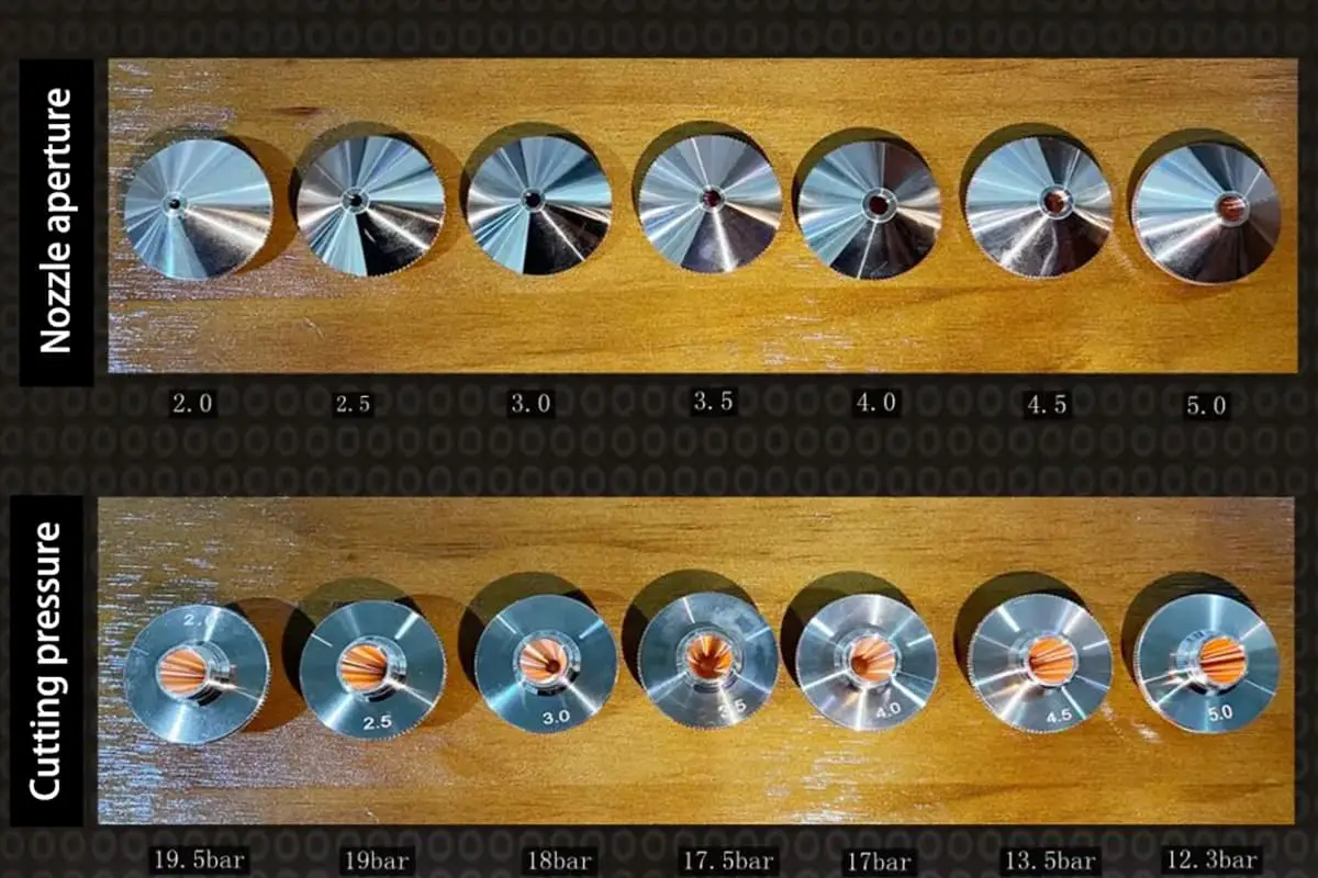
The kerf width generally increases with material thickness due to the need for higher laser power and longer dwell time. Additionally, the choice of cutting nozzle, assist gas pressure, and focal point position significantly influence the kerf width. Modern CNC laser cutting systems allow for precise control of these parameters to optimize kerf width and cut quality for specific applications.
It’s worth noting that advancements in laser technology, such as the implementation of beam shaping and ultra-short pulse lasers, are continually pushing the boundaries of achievable kerf widths and cut qualities across various materials and thicknesses.
Laser cutting machines have been in development for many years and have gradually become the mainstream processing equipment for metal processing.
However, there are always some issues with cutting, such as producing a cutting kerf that is too wide.
So, what are the factors that affect the kerf width of a laser cutting machine?
There are four main factors:
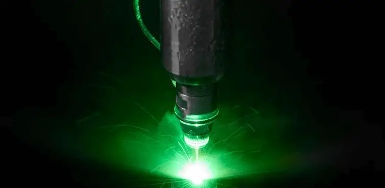
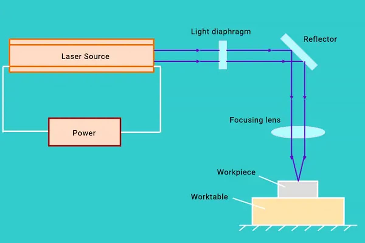
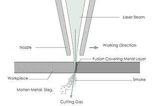
The laser beam generated by a laser is not emitted vertically, but at a scattering angle.
Therefore, when using a laser cutting machine to cut a workpiece, a certain taper will be formed. Thus, the quality of the laser beam is also critical for cutting.
Generally, the focus should not be adjusted arbitrarily after adjustment. It should only be adjusted when there are noticeable issues in the cutting effect.
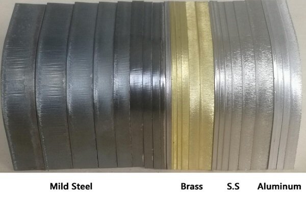
The actual cutting effect varies depending on the material being cut.
In laser cutting, a smaller spot from the laser beam produces a better cutting effect.
In addition to the quality of the laser beam affecting the spot, the workpiece material also affects the size of the spot.
For example, copper is highly reflective, which makes it challenging to form light spots. Therefore, the requirements of a copper laser cutting machine are higher compared to ordinary metals.
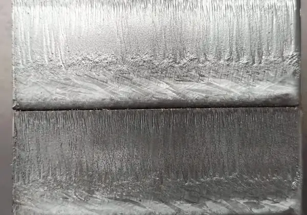
Under the same material and power cutting conditions, the thicker the material, the more likely it is to have burrs and unevenness on the cross-section.
To achieve the exact same section as the sheet material, the laser’s power needs to be increased.
The reason why the laser cutting machine is widely accepted is due to its fast cutting speed.
When other conditions remain constant, the cutting speed of a laser cutting machine must be appropriately adjusted to achieve the best cutting effect.
If the speed is too slow, the kerf’s roughness may be very large. If the speed is too fast, the kerf’s roughness may be reduced.
However, if the speed is too fast, it may not be able to penetrate the material, so it is essential to control the speed and not blindly pursue high-speed cutting.
In laser cutting processes, the relationship between cutting speed and kerf width is complex and influenced by multiple factors. When laser power and assist gas pressure remain constant, cutting speed exhibits a nonlinear inverse relationship with kerf width.
As cutting speed increases, the kerf width generally decreases. This occurs because the laser beam interacts with the material for a shorter duration, reducing the heat-affected zone (HAZ) and resulting in a narrower cut. Conversely, when cutting speed decreases, the kerf width tends to increase due to prolonged laser-material interaction and increased heat input.
The surface roughness of the cut edge demonstrates a parabolic relationship with cutting speed. At lower speeds, excessive heat input can cause irregular melting and increased dross formation, leading to higher surface roughness. As cutting speed increases, surface roughness typically improves due to more controlled material removal. However, an optimal cutting speed exists where surface roughness reaches its minimum value.
It’s crucial to note that if the cutting speed exceeds a critical threshold, the laser energy density becomes insufficient to fully penetrate the material, resulting in incomplete cuts or no cutting at all. This phenomenon is often referred to as the “speed limit” in laser cutting.
The interplay between cutting speed, kerf width, and surface quality is further influenced by factors such as material properties, thickness, laser wavelength, and beam characteristics. For instance, highly reflective materials like aluminum or copper may require different speed-power relationships compared to steel.
In practice, manufacturers often develop cutting speed charts or utilize advanced process monitoring systems to optimize these parameters for specific materials and thicknesses, ensuring high-quality cuts while maximizing productivity.
The most significant factor that affects the processing quality and capacity of a laser cutting machine is the focus position, and its specific relationship with processing is as follows.
The focus position is defined as the position after the laser beam is focused relative to the surface of the processed material.
The focus position affects nearly all processing parameters, such as the width, slope, roughness of the cutting surface, adhesion state of slag, and cutting speed.
This is because changing the focus position causes a change in the beam diameter on the surface of the processed material and the incident angle into the processing material.
Consequently, it affects the kerf’s formation state and the multiple reflections of the beam in the kerf, which affects the flow state of auxiliary gas and molten metal in the kerf.
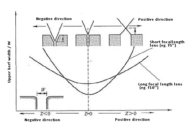
The figure shows the relationship between the focus position Z of a laser cutting machine and the kerf width W of the processed material surface.
The focus state on the processed material surface is set to Z = 0 “zero,” the focus position is represented by “+” when moving upward, “-” when moving downward, and the movement amount is in mm.
When the focus is at the focus position Z = 0, the upper kerf width W is the minimum.
Whether the focus position moves up or down, the upper kerf width W becomes wider.
This tendency is the same when processing lenses with different focal lengths.
The smaller the beam diameter at the focus position and the shorter the focal depth of the lens, the greater the variation of the upper kerf width with the focus position’s change.
| Focus position | Features | Application |
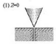 | The kerf is the narrowest and can be processed with high precision | Processing requiring slope reduction; Processing with high requirements for surface roughness; High speed cutting; Reduce the processing of heat affected zone; Micro machining |
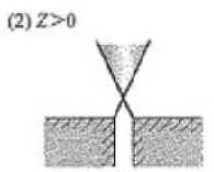
| Widening below the kerf, can improve the flow of gas and the fluidity of melt | CW and high frequency pulse processing of thick plate; Acrylic plate processing; Tool die processing; Ceramic tile processing |
 | Widening above the kerf, can improve the flow of gas and the fluidity of melt | Air cutting of aluminum; Nitrogen cutting of aluminum; Air cutting of stainless steel; Nitrogen cutting of stainless steel; Air cutting of galvanized steel sheet |
The figure above shows the best focus position of the metal laser cutting machine when processing various processing materials.
(1) The minimum beam diameter Z = 0 can be obtained at the material surface.
At this point, the maximum energy density can be obtained on the processed material surface, and the melting range is relatively narrow, which determines the processing characteristics.
(2) The focus position is on the “+” side (Z > 0).
At this point, the irradiation range of the laser beam on the processed material surface becomes wider, and the beam in the kerf has a diffusion angle, which increases the kerf width.
(3) The focus position is on the “-” side (Z < 0).
At this point, the range of the laser beam irradiated on the processed material surface becomes wider.
The closer the focus position is to the plate thickness direction, the higher the melting capacity, and then a reverse slope occurs.
Usually, during laser cutting machine processing, there are instances where a large cutting kerf occurs. This situation results in low cutting accuracy, which does not meet our requirements.
What is the reason for this situation? Is there a way to solve it?
After continuous observation and analysis, the technical engineer has devised three solutions:
The optical fiber focal length adjustment can be in manual or automatic form.
Manual focusing is prone to be forgotten by technicians, especially after lens replacement or cleaning; thus, the focal length should be readjusted.
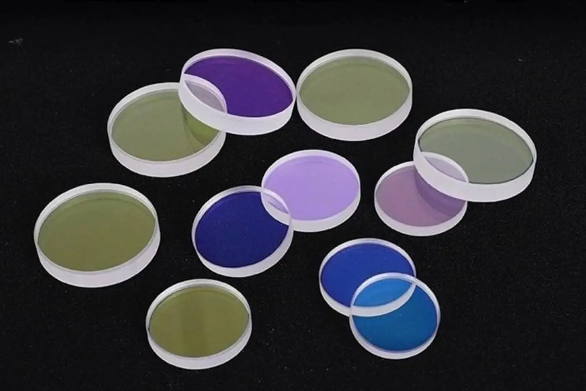
Check if the lens is damaged or dirty since this can cause laser scattering and beam thickening. Replacing or cleaning the lens is the only solution.
Check the quality of the laser spot.
If there are two points or the light spot is not round, the laser tube’s support point may require adjustment.
This reason is often neglected, but it still demands attention.
Large laser cutting seams are not a significant issue, but the equipment must undergo maintenance after production and processing for a certain period.
In fact, some minor irregularities may occur during use, which necessitates proper maintenance to ensure efficient and long-term laser cutting machine operation, and create the maximum value for users.
The factors influencing laser cutting kerf quality are multifaceted and intricate. As previously discussed, beyond the workpiece material properties, numerous parameters significantly impact kerf width and overall cut quality. These include laser beam characteristics (wavelength, mode, polarization), power output, cutting speed, nozzle geometry and standoff distance, focal position, assist gas type and pressure, and more.
To optimize cutting quality when operating a laser cutting machine, consider the following best practices:
1. Focal point optimization: Maintaining precise focal position is crucial for achieving high-quality kerfs. Proper focus minimizes burr formation, reduces edge burning, and prevents plate explosions. While focus typically remains stable once set, adjustments may be necessary when:
2. Regular maintenance: Implement a proactive maintenance schedule, including daily visual inspections and weekly lens cleaning/maintenance. This helps preserve optimal beam quality and prevents degradation of cut performance over time.
3. Trial cuts: Before processing production parts, always perform test cuts on scrap material of the same type and thickness. This allows for fine-tuning of parameters and ensures consistent quality throughout the production run.
4. Parameter optimization: Develop and maintain a database of optimized cutting parameters for different materials and thicknesses. Consider factors such as:
5. Material considerations: Ensure consistent material quality and proper storage/handling to minimize variations in cutting performance. Consider factors like surface condition, flatness, and potential contaminants.
6. Beam delivery system maintenance: Regularly check and clean all optical components in the beam path, including mirrors, lenses, and protective windows. Misalignment or contamination can significantly impact kerf quality.
7. Cutting head alignment: Periodically verify and adjust the cutting head’s perpendicularity to the workpiece surface, especially for bevel-sensitive applications.
8. Process monitoring: Implement real-time monitoring systems to detect variations in cut quality, allowing for rapid adjustments and minimizing scrap rates.
9. Operator training: Ensure that machine operators are well-trained in recognizing cut quality issues and making appropriate adjustments to maintain optimal performance.
See also:

