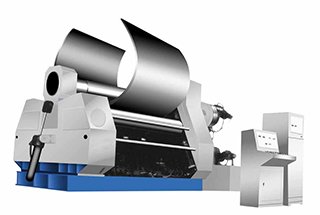
Have you ever wondered how metal sheets are bent into precise cylindrical shapes? This guide delves into the operation of the three-roller roll bending machine, a crucial tool in various industries such as construction, shipbuilding, and machinery. By understanding its structure, operation, and maintenance, you will gain insights into the mechanics behind creating perfectly rounded metal components. This article promises to equip you with the knowledge to operate this machine safely and efficiently, enhancing your metalworking skills.
In this article, our focus is on the three-roller asymmetric rolling machine.
This machine is primarily utilized in the cold working process to bend sheets into cylindrical tubes of varying diameters.
The plate roll bending machine is widely used in various industries, including the boiler, chemical, mining, construction, shipbuilding, and machinery industries.
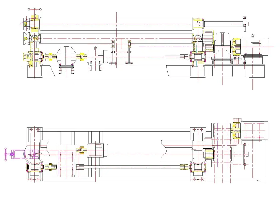
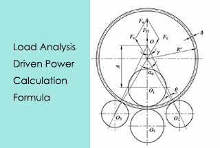
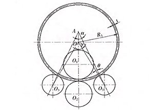
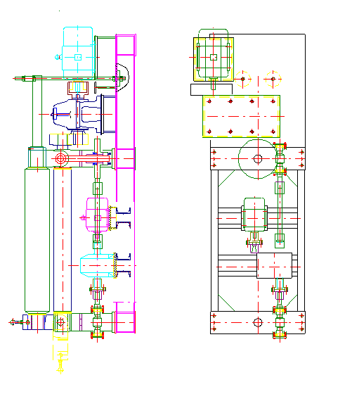
Here are the drawings:
Plate roll bending machine specifications
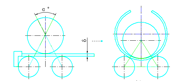
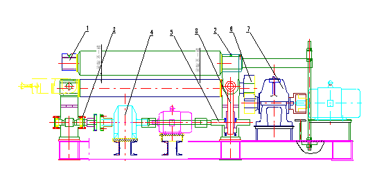
3-1. This is a symmetric roll-bending machine.
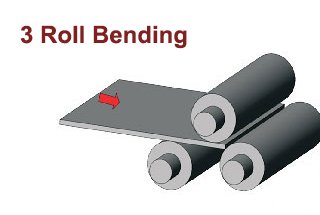
The cylinder rolling is accomplished through the upper roller pressing against the lower roller, with both rollers participating in the rolling process. This is depicted in Drawing 3-1.
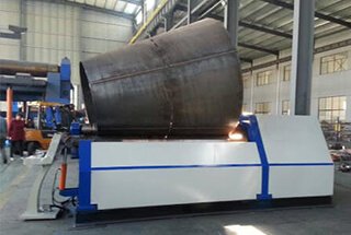
3-2. The machine consists of two parts: the operating section and the transmission section, which are welded together on a single bottom pallet.
The operating section includes the left and right bearing housing, one upper roller, two lower rollers, lifting gears, and additional accessories. The lower roller is the primary roller, while the height of the upper roller can be adjusted. The transmission section consists of the main motor, the speed-reducing motor, and other accessories.
3-3. The lower roller is driven by the main motor through the main reduction gearbox. The output shaft of the main gearbox transmits to the two lower rollers through a set of gears. The direction of the roller’s rotation is controlled by the main motor.
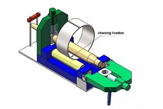
3-4. The elevation movement of the upper roller is achieved by the auxiliary motor through the auxiliary gearbox, which drives the worm and worm wheel located under the left and right roller bearing. This movement is automatically controlled and completed by the rotation of the steel wire nut, which is fixed to the worm wheel, and the up and down movement of the ball bearing screws, as shown in Drawing 3-4.
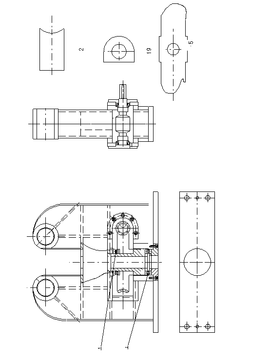
( 3-4) Bracket Assembly Graphics
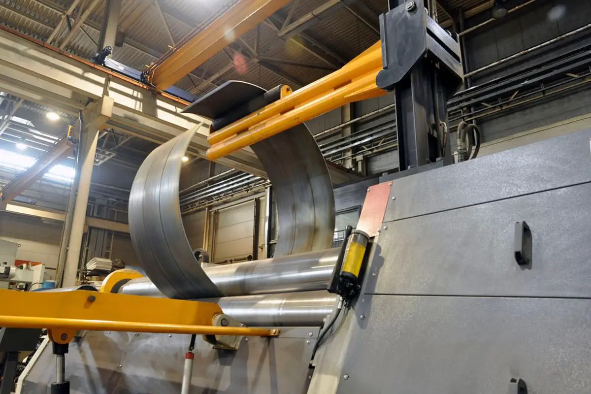
3-5. The unloading device is used once the cylindrical rolling is complete.
The upper roller is raised to the standard height, and it is stopped in place using a balance pull rod located at the bottom of the upper roller. The pin shaft on the tilting bearing seat is then removed, causing the tilting bearing seat to overturn, allowing the coiled product to be removed from one end of the upper roller.
3-6. The key components of the rolling machine include three 45 steel forged rollers with a hardness of 35-45 HRC, a welded support frame, a lower pallet that is also a welded part, ball bearing screws, and worm gears that are 45 steel forged components.
3-7. The electrical parts are of high quality and well-known brands, with reliable and consistent performance, durability, and safety. They are also easy to operate.
Lubricating oil is necessary for every area where friction occurs to ensure normal operation and increase the lifespan of the machinery.
The lubricating oil used in the speed-reducing case is typically mechanical oil HJ-40. It is important to regularly add lubricating grease to the gear wheel and refill the oil in the oil refilling cup, as shown in Drawing 4-1.
The upper roller overturning bushings need to have oil refilled every shift.
The oil in the upper roller orientation seat should be refilled once per shift.
The worm bearing requires oil refilling every 1,500 hours, depending on usage conditions.
The JZQ gearbox should have its oil replaced after the first three months of use and then every six months thereafter (using 2kg gear oil).
The oil in the worm wheel should be refilled as needed, typically every 1,500 hours.
The transmission gear wheel should have its oil refilled as needed, typically every 100 hours.
The ZSY224 gearbox should have its oil replaced after the first three months of use and then every six months thereafter (using 20kg gear oil).
The oil in the lifting ball bearing screw should be refilled as needed, typically every 800 hours.
The roller holes under the bracket should have oil refilled every shift.
1). Electrical Parameters
2). The Installation Connection
Connect the motor and control wires and ensure that the grounding is securely connected. Then verify that the insulation resistance is within safe limits. The machine cannot be operated without load until it has been confirmed to be in good condition.
Note: (Ensure that the motor wiring is properly connected and that the forward and reverse rotation of the motor is correct. Also confirm that the movement of the lower rollers and upper roller is correct).
The ground plane and slope level in any direction must not exceed 2 mm/m.
Before installation, inspect the machine to ensure it is in good working condition and prepare thoroughly.
Use the lower roller surface as the reference, check the horizontal gradient and parallel alignment between the upper and lower roller, and adjust as necessary to meet requirements.
After installation and successful inspection, tighten all bolts.
Ensure that the equipment has free movement after installation.
Before starting operation, inspect all joints for stability, check and adjust the clearance of all operating parts and joints.
Verify that all switches are in good working order.
After running a test for approximately 10 minutes, stop and inspect all components to ensure they are functioning properly before beginning operation.
Procedures for Treating All Types of Head.
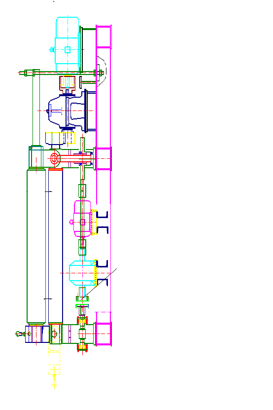
The equipment is designed for easy and convenient operation, while ensuring safety and reliability. To achieve different directions of turning and rise & fall, press the “Rotate” button (lower roller rotates), “Reverse” button (lower roller reverses), “Up” button (upper roller rises), or “Down” button (upper roller falls). The operator should adhere to the following principles:
8-1. Notice for lifting and moving the machine:
8-2. Avoid lifting the machine in a lopsided manner to prevent damage.
8-3. During lifting, do not allow any collisions with the components’ surface.
8-4. To prevent damage to the machine, ensure it is securely fastened and take measures for waterproofing and anti-rust.
8-5. Notice for machine maintenance:
When the machine is not in use for an extended period, lower the upper roller to touch the lower roller, switch off the power, and clean the machine. Take measures for moisture-proofing, anti-rust, and dust-proofing to prevent damage.
8-6. Before using the machine, open the machine cover and inject reducer oil.
Here are the drawings:
Groundwork Installation Drawings
Here are the drawings:

