Are you an aspiring mechanical engineer looking to excel in your field? In this blog post, we’ll explore the top 10 must-know mechanical engineering design software that can elevate your skills and boost your career. Discover the powerful tools used by industry experts and learn how they can help you tackle complex design challenges with ease. Get ready to take your mechanical engineering prowess to new heights!
If you aspire to become a specialist in manufacturing, it is imperative to have knowledge of at least three engineering design software.
Mechanical design is a crucial stage in the production process, and it plays a pivotal role in determining the performance of mechanical systems.
In order to achieve high standards of performance in mechanical products, computer technology is extensively utilized in mechanical design to support design processes and conduct system analysis.
Here are the top ten most widely used mechanical engineering design software globally:
As a mechanical expert, are you familiar with using these tools?
Autodesk Moldflow Adviser is a part of Autodesk’s digital prototyping solution, providing a user-friendly tool for simulating and evaluating design plans, enabling optimization before manufacturing.
This tool assists in minimizing potential design flaws, reducing product development cycles, and lowering development costs.
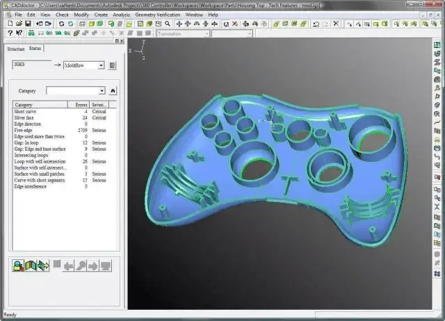
In the field of product design and manufacturing, Moldflow offers two significant simulation analysis software programs: Moldflow Plastic Parts Consultant (AMA) and Moldflow Advanced Molding Analysis Expert (AMI).
AMA is user-friendly and provides prompt responses to designers’ analysis needs and modifications, making it primarily aimed at injection product design engineers, project engineers, and die design engineers.
It allows them to quickly verify the feasibility of their products during the early stages of development.
AMA provides quick answers to fundamental manufacturing feasibility inquiries, such as “Can the product be filled?”
With this innovative design approach, both experienced experts and beginners can experience the dependability and practicality of injection molding simulation through AMA.
Moldflow overall solution
With the rapid growth of the plastics industry and related industries, competition within the industry has become increasingly intense.
Raw material costs and labor expenses are continuing to escalate, while product prices are declining. At the same time, the demands for product quality, functionality, and a shorter delivery timeline are persisting.
AutoCAD is an automated computer-aided design software developed by Autodesk that can be used for drafting, 2D drafting, and basic 3D design.
It enables automatic drawing without the need for programming knowledge, making it widely used globally.
AutoCAD can be applied in various fields, including civil construction, decoration, industrial drafting, engineering drafting, electronics, clothing processing, and many others.

Although AutoCAD boasts impressive graphic capabilities, its table processing functions are relatively weak.
In professional work, the need to create various tables in AutoCAD, such as engineering quantity tables, arises frequently. Hence, the question of how to efficiently create tables becomes a practical concern.
AutoCAD has several methods for creating basic graphic objects, such as straight lines, circles, ellipses, polygons, and splines.
Drawing aids.
AutoCAD provides several drawing aids, including orthogonal lines, object snaps, polar tracking, and object snap tracking.
The orthogonal function allows users to effortlessly draw horizontal and vertical straight lines.
Object snaps assist in selecting specific points on geometric objects, and tracking makes it easier to draw diagonal lines and locate points in varying directions.
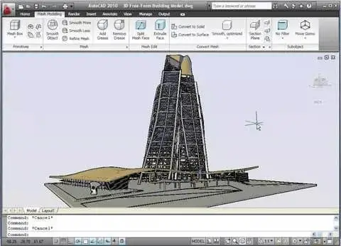
Since AutoCAD 2000, the system has introduced many powerful features.
These include the AutoCAD Design Center (ADC), Multi-Document Environment (MDE), internet drive, improved object snap functions, advanced annotation capabilities, and partial open and partial load functions.
Pro/Engineer is an integrated 3D CAD/CAM/CAE software developed by PTC, a US-based company.
It is well-known for its parametric capabilities and was one of the first software to introduce parametric technology. Pro/Engineer holds a significant position in the current 3D modeling software landscape.
Today, Pro/Engineer is widely acknowledged and promoted in the industry as a new standard in the field of mechanical CAD/CAE/CAM. It is considered one of the leading CAD/CAM/CAE software, particularly in the field of product design in China.
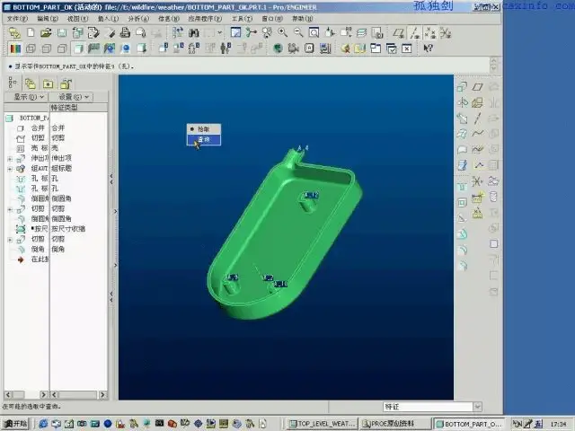
Pro/Engineer operates on a unified base database, which is different from traditional CAD/CAM systems that are built on multiple databases.
This single database ensures that all project materials come from the same source, allowing each user, regardless of department, to work on the same product model.
As a result, changes made in any stage of the design process are reflected throughout the entire design process, providing greater efficiency and consistency.
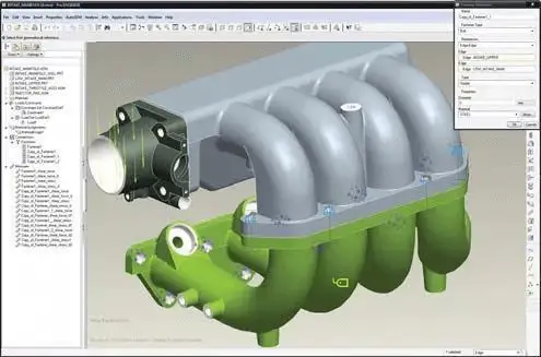
In the Pro/Engineer software version, in addition to using major versions like proe2001, Wildfire, WildFire2.0, WildFire3.0, WildFire4.0, and WildFire5.0, there are also minor version differences in date codes within each major version.
These different date codes represent the order of the release date of the major version.
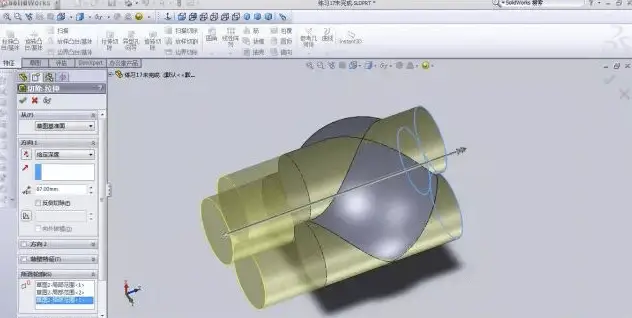
SolidWorks is a 3D design software originally built on the Windows system.
With its user-friendly interface and ease of use, SolidWorks can automatically capture design intent and guide design changes throughout the entire product design process.
In SolidWorks assembly design, new parts can be generated directly by referencing existing parts.
Regardless of whether the design process uses a “top-down” or “bottom-up” approach, SolidWorks operations make it easier to improve design efficiency.

Users are not only using SolidWorks software to address general part design issues but are also increasingly turning to it to tackle large-scale assembly designs at a system-level.
Due to the growing demand from users, the R&D department of SolidWorks has significantly improved the upload speed of large assemblies through various means, such as distributed data processing and the implementation of graphics compression technology.
This has resulted in a tenfold improvement in the performance of large assemblies.
UG, also known as UnigraphicsNX, is a product engineering solution developed by Siemens PLM Software. It offers digital modeling and verification tools for product design and manufacturing.
UnigraphicsNX is a reliable solution for virtual product design and process design needs of users.
Although UG can be commonly used as an abbreviation for the user guide and Universal Grammar, it is primarily associated with UnigraphicsNX in the context of product engineering software.
Additionally, in the game DOTA, it is referred to as Spectre.
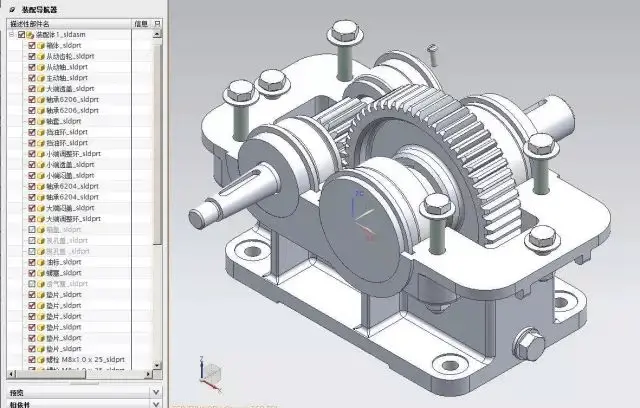
The development of UG (UnigraphicsNX) began in 1969 and was built using the C language.
It is a flexible numerical software tool for solving partial differential equations, which uses adaptive multigrid methods on two- and three-dimensional unstructured grids.
UG is an interactive CAD/CAM (computer-aided design and computer-aided manufacturing) system with strong functions that allow for easy construction of various complex entities and shapes.
Initially, it was mainly used on workstations. However, with the advancement of PC hardware and the increasing number of individual users, its application on PCs has rapidly grown, and it has become a mainstream 3D design solution in the die industry.
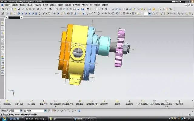
By using NX for modeling, industrial designers can quickly create and improve complex product shapes. They can also use advanced rendering and visualization tools to maximize the aesthetic requirements of the design concept.
Cimatron is a product from the well-known Israeli software company, Cimatron.
In China, Cimatron’s subsidiary is Simetron (Beijing) Technology Co., Ltd. The company is now owned by 3D Systems in the United States.
Over the years, Cimatron’s CAD/CAM solutions have proven to be an indispensable tool for enterprises of all sizes, from small die manufacturing plants to large manufacturing departments worldwide.
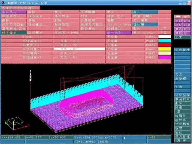
Since its founding in 1982, Cimatron’s innovative technology and strategic direction have made it a recognized leader in the CAD/CAM field.
As a leader in CAD/CAM integrated solutions for manufacturing, Cimatron promises to provide comprehensive and cost-effective software solutions for die, tool, and other manufacturers.
These solutions can streamline the manufacturing cycle, strengthen manufacturers and external sales, as well as improve supplier collaboration to greatly shorten product delivery time.
Whether designing for manufacturing or generating safe, efficient, and high-quality NC tool paths for 2.5-5 axis milling, Cimatron’s manufacturing-oriented CAD/CAM solutions provide customers with the ability to handle complex parts and manufacturing cycles.
Cimatron guarantees that every product manufactured is the product you designed.
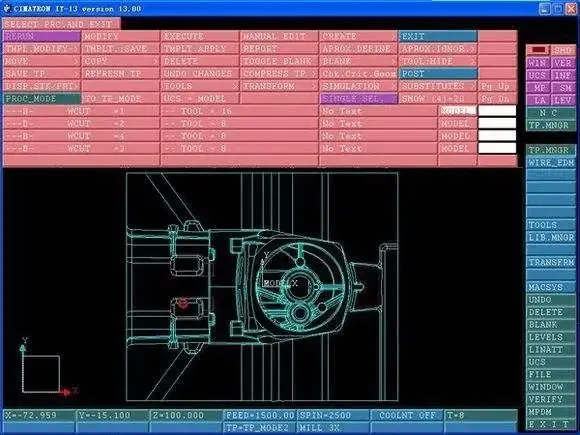
Cimatron has launched the new Chinese version, CimatronE10.0.
Its CAD/CAM software solution includes a set of tools for easy 3D design, allowing users to conveniently process the acquired data model or carry out product conceptual design.
Version 10.0 has made significant improvements in design and data interface.
Today, over 4,000 customers worldwide are using Cimatron’s CAD/CAM solutions to manufacture products for various industries, including automotive, aerospace, computer, electronics, consumer goods, medicine, military, optical instruments, communications, and toy industries.
Mastercam is a CAD/CAM software platform developed by CNC Software Inc. in the United States for use on personal computers. It offers a range of functions, such as 2D drawing, 3D solid modeling, surface design, voxel stitching, numerical control programming, tool path simulation, and realistic simulation.
The software has a user-friendly interface for geometric modeling and provides an ideal environment for designing parts, including complex curved shapes. Its robust and stable modeling capabilities make it widely used in both industrial and educational settings.
Additionally, Mastercam 9.0 and above versions include support for the Chinese language, making it a popular and cost-effective choice for small and medium-sized enterprises.
It is an economical and effective all-around software system, commonly used in both industry and educational institutions.

Mastercam not only offers powerful and stable modeling functions for designing complex curves and surface parts but also provides robust surface roughing and flexible surface finishing capabilities.
Its reliable tool path verification function allows Mastercam to simulate the entire part processing process.
The simulation not only displays the tools and fixtures but also checks for interference and collisions between the tools, fixtures, and processed parts, which accurately reflects the actual processing situation.
Mastercam is an excellent CAD/CAM software due to its comprehensive features and capabilities.
Furthermore, it has relatively low system requirements, enabling users to achieve optimal results in processing operations such as modeling design, CNC milling machines, CNC lathes, or CNC wire cutting.
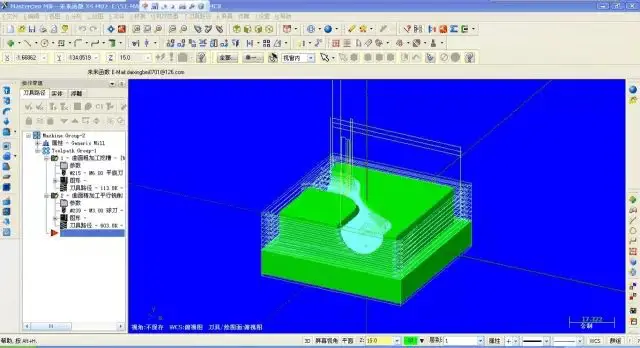
Mastercam offers powerful surface roughing and flexible surface finishing functions. It provides a range of advanced roughing technologies to improve the efficiency and quality of parts processing.
Mastercam also has various curved surface finish machining functions, allowing users to choose the best method to process even the most complex parts. Its multi-axis machining function provides more flexibility for parts processing.
Mastercam’s ease of use is a significant advantage in CNC machining. The generated NC programs are simple and efficient.
Main competitors of Mastercam include UGNX, Edgecam, WorkNC, Cimtron, Delcam (Powermill), PTC (Pro/NC), Space-e, CAMWORKS, and HyperMILL, etc.
Compared to these software, Mastercam has an overwhelming advantage in 2D processing. It also has an advantage in simple rule-based surfaces.
For multi-axis surfaces, the introduction of third-party 5-axis multi-surface machining in X3 keeps it as the king of general CNC machining.
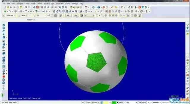
Mastercam software is extensively used in the design and NC processing of general machinery, aviation, shipbuilding, military industries, and others.
Since the late 1980s, China has introduced this well-known CAD/CAM software, which has made significant contributions to the rapid growth of the manufacturing industry in China.
CATIA is Dassault’s flagship solution for product development in France.
It is a crucial component of the PLM collaborative solution, helping manufacturers design their future products and supporting the entire industrial design process, from pre-project planning to specific design, analysis, simulation, assembly, and maintenance.
Its digital prototyping process has gained widespread adoption in the market since 1999, making it the most widely used product development system globally.
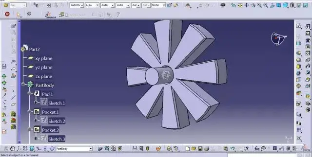
The modular CATIA series offers product style and appearance design, mechanical design, equipment and system engineering, management of digital prototypes, mechanical processing, analysis, and simulation.
CATIA products are based on an open and scalable V5 architecture. With CATIA’s intelligent tree structure, users can quickly and easily modify products repeatedly, even in the final stages of design or when updating the original scheme.
CATIA provides complete design capabilities from the conceptual design of a product to the formation of the final product.
Its accurate and reliable solutions provide a complete 2D, 3D, parametric hybrid modeling, and data management capabilities from the design of a single part to the establishment of the final electronic prototype.
As a fully integrated software system, CATIA combines mechanical design, engineering analysis and simulation, CNC machining, and CATweb network application solutions to provide users with a strict paperless working environment, especially in the special modules for the automobile and motorcycle industries.
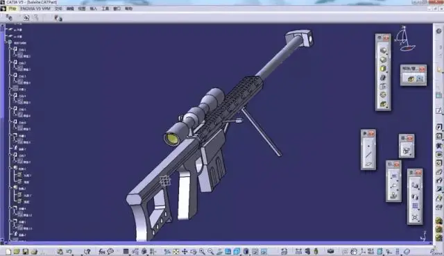
CATIA offers convenient solutions to meet the needs of large, medium, and small enterprises in all industrial fields, including products ranging from large Boeing 747 aircraft and rocket engines to cosmetic packaging boxes, covering almost all manufacturing products.
The CATIA series provides 3D design and simulation solutions in eight areas: automotive, aerospace, shipbuilding, plant design, construction, power and electronics, consumer goods, and general machinery manufacturing.
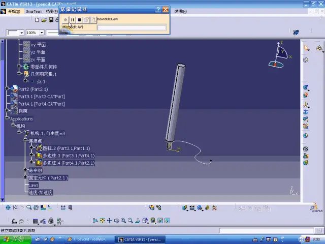
CATIA’s competitors include UGNX, Pro/E, Topsolid, and Cimatron. NX, Pro/E, and CATIA individually occupy about one-third of the global market share.
CATIA currently holds the largest market share in design and engineering software, thanks to its strong customer base and military background.
Compared to its competitors, CATIA’s advantage lies in its user-friendly interface, powerful features, strong functional support in special industries like automobiles, aerospace, shipbuilding, etc., and global sales cooperation with IT giant IBM.
Delcam is a well-known professional CAD/CAM software company based in Birmingham, United Kingdom. It is publicly listed on the London Stock Exchange and started its software development at Cambridge University, a globally recognized institution.
With over 40 years of development, Delcam’s software covers a wide range of applications, including product design, die design, product processing, mold processing, reverse engineering, art design, engraving processing, quality inspection, and collaboration management.
Delcam’s ongoing software research and development takes place in both the United Kingdom and the United States. It has a global customer base of over 40,000 spread across 80 countries and regions worldwide.

Delcam is a CAD/CAM software company that has been in the industry for over 40 years. It integrates design, manufacturing, measurement, and management and focuses on research, development, and technical services. Delcam believes that everything is for the sake of users, which is the key to its success.
Delcam not only provides users with leading software solutions but also offers the highest level of technical support through over 350 technical support branches in more than 80 countries and regions worldwide. This ensures that Delcam can solve any user problems with the fastest response time.
Delcam is the only CAD/CAM software company with a large CNC machining workshop globally.
All Delcam software products have undergone rigorous testing in actual production environments. This enables Delcam to best understand the problems and needs of users and provide a complete set of products from design, manufacturing, testing, to management.
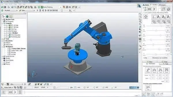
The Delcam CAD/CAM series software is widely used in industries such as aerospace, automobiles, ships, household appliances, light industrial products, and mold manufacturing.
Well-known companies like Airbus, Boeing/McDonnell Douglas, Hafei, XAC, Chengfei, Toyota, Honda, Ford, Volkswagen, MercedesBenz, Pratt&Whitney, Siemens, Mitsubishi, Canon, LG, Nike, Clarks, FAW Group, Dongfeng Motor Group, and Zhuhai Gree are all Delcam users.
Edgecam is an automated CNC programming software developed by Planit in the United Kingdom. It seamlessly integrates with commonly used CAD software, allowing for seamless data transmission.
Edgecam leverages the relationship between entity and tool path, automatically reflecting modifications made to the geometric features of the entity in the tool path, such as height, depth, and diameter, without requiring additional editing.
Edgecam provides comprehensive solutions for milling, turning, and combined mill-turn processing methods.
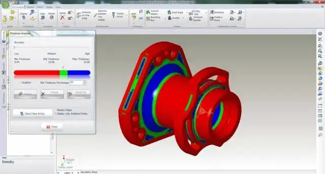
EdgeCAM is a powerful, versatile, easy-to-learn, and user-friendly intelligent CNC programming system that adopts a modular design to meet the needs of different users.
Users can choose modules with different functions to create a customized CAM solution for CNC machining programming that fits their programming needs.
The R&D and promotion of EdgeCAM products focus on meeting the needs of global processing and manufacturing users, providing them with the latest CNC programming functions at the fastest speed to meet the different requirements of different users.
After more than 20 years of product development and application, EdgeCAM has over 40,000 authorized users worldwide.
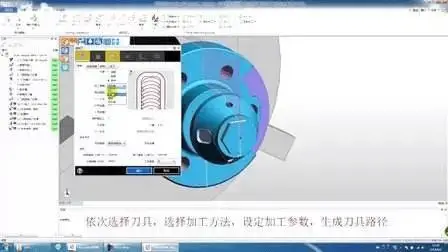
Planit Group is the leading global manufacturer in terms of installed CAM software. With 84,000 units installed, it surpasses its competitors in the same industry by 24,000 units and exceeded its own sales in 2005 by nearly 30,000 units.
Planit Group’s portfolio includes EdgeCAM, AlphaCAM, Radan, and other CAM software, providing a diverse range of products that secure and strengthen its position in the manufacturing industry.
Edgecam specifically caters to the die industry, offering various processing methods to meet different processing needs, including optimized processing for various product processing methods, mold manufacturing, turning, composite processing, and high-speed processing.
When comparing mechanical engineering software options, several key factors must be considered to ensure the best fit for specific needs and workflows. These factors include the software’s complexity, scalability, industry preferences, and integration capabilities.
AutoCAD is known for its user-friendly interface, making it accessible for beginners while still powerful enough for advanced users. It can handle both simple and complex projects, making it suitable for a wide range of applications from basic drafting to intricate 3D modeling.
AutoCAD is widely used in the architecture, automotive, and aerospace industries due to its precision and versatility in creating detailed technical drawings. For instance, an architectural firm might use AutoCAD to create floor plans, elevations, and sectional views, ensuring high accuracy and detail.
AutoCAD’s interoperability with other design software streamlines the engineering workflow, allowing for seamless integration with various CAD, CAM, and CAE tools. This facilitates a smooth transition from design to manufacturing.
SolidWorks offers a robust set of features for parametric modeling, making it ideal for users with some experience in CAD software. It excels in managing complex assemblies and large-scale projects, particularly in the automotive and aerospace industries.
SolidWorks is favored in the automotive and aerospace sectors for its parametric modeling and assembly creation capabilities. It is also popular in the consumer electronics industry for designing complex internal components. For example, an aerospace company might use SolidWorks to design and simulate the aerodynamics of an aircraft wing.
SolidWorks integrates well with other engineering software, enhancing its capabilities in parametric modeling, simulation, and manufacturing processes. This integration supports a comprehensive design-to-production workflow.
Inventor provides advanced modeling options and simulation tools, which may require a steeper learning curve. It is designed to handle large projects, such as electrical engineering and transmission structures, making it suitable for extensive and detailed work.
Inventor is commonly used in mechanical engineering and industrial equipment sectors, benefiting companies working on large-scale and complex projects. For instance, an engineering firm might use Inventor to design and test the structural integrity of a new piece of heavy machinery.
Inventor offers robust integration with other Autodesk products, providing a cohesive environment for design, simulation, and visualization. This integration helps streamline complex project workflows.
CATIA is known for its advanced capabilities, including surface modeling and FEA, which can be complex for new users. It is highly scalable and used for large-scale projects in the aerospace and automotive industries, supporting intricate and precise modeling.
CATIA is extensively used in the aerospace and automotive industries for its advanced modeling and simulation capabilities, enabling the design of intricate components and systems. For example, an automotive company might use CATIA to design the complex geometry of a car’s exterior body.
CATIA’s integration with Dassault Systèmes’ PLM solutions ensures efficient management of product lifecycle and collaboration across different engineering teams. This integration supports comprehensive project management from conception to production.
Siemens NX offers a comprehensive toolset that includes CAD, CAM, and CAE, which can be complex but provides a complete solution for engineering needs. It is particularly useful for managing highly complex projects, integrating conception, simulation, and manufacturing processes.
Siemens NX is preferred in the heavy machinery and shipbuilding industries, where managing large and complex assemblies is crucial. For instance, a shipbuilding company might use Siemens NX to design and simulate the structural components of a new vessel.
Siemens NX provides a complete solution by integrating CAD, CAM, and CAE functionalities, streamlining the entire design-to-manufacturing workflow. This integration supports efficient project execution and reduces time to market.
By considering these factors, mechanical engineers can select the most appropriate software to enhance their design, analysis, and manufacturing processes, ensuring optimal performance and efficiency in their projects.
Mechanical engineering software preferences vary significantly across different industries due to the unique requirements and complexities of each sector. This chapter provides a comprehensive overview of the most preferred software tools in key industries, with specific examples and detailed explanations of their applications.
The automotive industry demands software that excels in both design and simulation to ensure safety, efficiency, and innovation.
CATIA
CATIA is widely used for its advanced surface modeling and parametric capabilities, essential for designing complex automotive components and systems. For instance, CATIA was pivotal in the development of the aerodynamic design of the Tesla Model S, where engineers used its robust simulation tools to optimize vehicle aerodynamics and structural integrity.
SOLIDWORKS
SOLIDWORKS is favored for its comprehensive design and simulation features. It allows engineers to create detailed models and perform stress analysis on various vehicle parts. Ford Motor Company has utilized SOLIDWORKS to streamline the design process for engine components, ensuring durability and performance under various operating conditions.
Siemens NX
Siemens NX is known for managing large assemblies and integrating CAD, CAM, and CAE functionalities, making it ideal for complex automotive projects. BMW employs Siemens NX for the entire product development cycle, from concept to manufacturing, to enhance efficiency and reduce time-to-market.
Aerospace engineering requires precise and reliable software for designing and analyzing highly complex systems.
CATIA
CATIA’s advanced capabilities in surface modeling and finite element analysis (FEA) make it indispensable for aerospace projects. Airbus used CATIA to design the A380’s wing structure, performing aerodynamic simulations to ensure compliance with stringent industry standards.
ANSYS
ANSYS is renowned for its powerful simulation tools, extensively used in the aerospace sector for FEA and computational fluid dynamics (CFD). NASA utilized ANSYS to predict the behavior of spacecraft components under various stress conditions, significantly reducing the need for physical prototypes.
Siemens NX
Siemens NX provides comprehensive tools for design, simulation, and manufacturing. Boeing uses Siemens NX to handle large, complex assemblies and integrate with other engineering tools, ensuring efficient project execution for aircraft development.
In general manufacturing, versatility and integration capabilities are key.
AutoCAD
AutoCAD is widely used for creating detailed 2D and 3D designs, essential for drafting and modeling in various manufacturing applications. General Electric (GE) relies on AutoCAD for the precise design of industrial machinery components, enhancing productivity with its extensive library of symbols and templates.
Inventor
Inventor offers robust tools for design, simulation, and visualization. It supports parametric and rule-based design, making it ideal for automating repetitive tasks. Siemens uses Inventor to ensure design accuracy and streamline the production process of electrical equipment.
Fusion 360
Fusion 360 combines CAD, CAM, and CAE capabilities, making it suitable for collaborative projects in manufacturing. Dyson utilizes Fusion 360 for rapid prototyping and testing of vacuum cleaner components, facilitating efficient design iterations.
The healthcare industry requires precision and compliance with regulatory standards.
SOLIDWORKS
SOLIDWORKS is widely used in the design of medical devices, allowing for precise control over dimensions and materials. Johnson & Johnson employs SOLIDWORKS to develop surgical instruments, ensuring they meet safety and performance criteria.
Creo
Creo offers robust parametric modeling and simulation tools, ideal for designing complex medical devices. Medtronic uses Creo for rapid prototyping and end-use product production, ensuring the reliability and functionality of medical implants.
The energy sector requires software that can handle complex engineering challenges and ensure safety and efficiency.
Solid Edge
Solid Edge offers powerful simulation capabilities, making it suitable for complex engineering projects in the energy industry. Siemens Energy uses Solid Edge’s synchronous technology to combine direct modeling with parametric design, enhancing flexibility and precision in the development of power generation equipment.
ANSYS
ANSYS is extensively used for simulating and analyzing energy systems. Shell employs ANSYS to optimize the design of oil and gas extraction equipment, ensuring efficiency and safety under various environmental conditions.
In the consumer products and electronics industry, innovation and rapid prototyping are critical.
Fusion 360
Fusion 360’s cloud-based platform supports collaborative design and prototyping. Apple uses Fusion 360 for the design and testing of new electronic devices, streamlining the product development process with its integrated CAD, CAM, and CAE capabilities.
SOLIDWORKS
SOLIDWORKS is widely used in designing intricate electronic components and consumer products. Sony leverages SOLIDWORKS to create detailed models and perform comprehensive simulations, ensuring product reliability and performance.
Each industry has specific needs and challenges, influencing the choice of mechanical engineering software. By selecting the most appropriate tools, engineers can enhance their design, analysis, and manufacturing processes, ensuring optimal performance and innovation.
Emerging technologies like AI and machine learning are set to revolutionize collaboration tools in mechanical engineering. These technologies can automate routine tasks, provide predictive analytics for project management, and enhance real-time collaboration through advanced simulations and virtual reality environments. Adopting these trends will further streamline workflows and improve project outcomes.
| Tool | Key Features | Benefits |
|---|---|---|
| GrabCAD Workbench | Viewer, markup tools, real-time updates | Reduced revision time by 30% |
| Onshape | Cloud-based, real-time collaboration, revision control | Design cycle reduction by 40% |
| Fusion 360 | Integrated CAD, CAM, CAE, PCB capabilities | 25% increase in productivity |
| Fellow.app | Meeting agendas, notes, action items, integrations | Improved meeting efficiency by 20% |
| Plaky | Task management, customizable templates, notifications | 15% reduction in project delays |
| Jira | Agile project management, real-time tracking, reporting | 30% improvement in project delivery times |
| CoLab | Design review, collaboration, integration with CAD/PLM | 25% reduction in design review cycle |
| Valispace | Real-time requirements, system model integration | 30% reduction in design errors |
These tools, when effectively implemented, can significantly enhance the collaboration and efficiency of mechanical engineering teams, leading to more successful project outcomes.
Choosing the right mechanical engineering software is crucial for enhancing design capabilities, streamlining workflows, and delivering high-quality results. In modern engineering practices, the right software can significantly impact the efficiency and success of projects. This guide outlines key factors to consider when making this decision.
Below are answers to some frequently asked questions:
When selecting the best CAD software for mechanical engineers, several top contenders stand out based on their unique strengths and applications. SOLIDWORKS, developed by Dassault Systèmes, is widely regarded for its comprehensive design and simulation tools, including 2D and 3D modeling, stress analysis, and detailed manufacturing drawings. Its user-friendly interface and extensive community support make it a favorite among mechanical engineers.
Fusion 360 by Autodesk is another excellent choice, particularly noted for its cloud-based capabilities that integrate CAD, CAM, and CAE functions. It excels in collaborative features, making it ideal for remote teams, and offers advanced simulation and manufacturing tools.
CATIA, also from Dassault Systèmes, is highly valued in the automotive and aerospace industries due to its advanced tools for designing complex mechanical parts and systems, including surface and parametric modeling and finite element analysis (FEA).
Siemens NX provides a robust CAD/CAM/CAE solution with advanced capabilities for complex mechanical design and integrated simulation and manufacturing functionalities. Its high level of customization and multi-format support make it suitable for large-scale industrial projects.
PTC’s Creo is known for its robust functionality and ease of use, offering parametric and assembly modeling and simulation, making it a strong option for product development and manufacturing.
Autodesk’s Inventor offers a comprehensive set of tools for design, simulation, and visualization, supporting parametric and rule-based design, and integrating well with other Autodesk products.
For those needing versatility, KeyCreator by Kubotek3D provides powerful tools for mechanical design, modeling, and analysis, with features like direct editing and hybrid modeling.
AutoCAD, while primarily known for its 2D capabilities, also offers robust 3D modeling tools and is widely used for precise and detailed designs in the mechanical engineering field.
Ultimately, the best CAD software depends on the specific needs of the project, including the complexity of the designs, the need for collaboration, ease of use, and available simulation and analysis tools. Each of these software options provides distinct advantages that cater to different aspects of mechanical engineering tasks.
FEA (Finite Element Analysis) and simulation software offer significant benefits to mechanical engineers, making them vital tools in the design and analysis process. These software tools enable engineers to predict the behavior of complex systems and structures under various conditions, such as stress, strain, thermal stress, and vibrations. By providing accurate predictions and allowing for virtual testing, they help in validating designs, reducing the need for physical prototypes, and minimizing associated risks, costs, and time.
One of the primary advantages of FEA software is design optimization. Engineers can analyze and compare multiple design options quickly, facilitating the creation of efficient, safe, and compliant designs. This iterative process helps in making informed decisions based on simulation results. Additionally, FEA reduces development time and costs by identifying design flaws early in the design process, which minimizes material waste and speeds up the development cycle.
Safety is another critical benefit of FEA software. It allows engineers to design structures that meet safety requirements by predicting performance under different loading conditions and identifying potential failure modes. This capability ensures that the final structures are both safe and reliable.
FEA software also supports multidisciplinary simulations, enabling the modeling of various physical phenomena such as structural mechanics, heat transfer, fluid dynamics, and electromagnetics. This versatility allows for the analysis of complex interactions between different components and systems, which is essential for comprehensive design evaluations.
Moreover, modern FEA software enhances collaboration among design teams and stakeholders by providing a shared platform for design and analysis. This facilitates information sharing, communication of design changes, and collective problem-solving to achieve project goals.
FEA is widely applicable across various engineering disciplines, including mechanical, civil, aerospace, and biomedical engineering. It is particularly valuable in industries where physical testing is impractical or impossible, such as in the design of aircraft components, automotive systems, and large civil structures like bridges and dams.
In summary, FEA and simulation software benefit mechanical engineers by offering accurate predictions, enabling design optimization, reducing development time and costs, improving safety, supporting multidisciplinary simulations, enhancing collaborative workflows, and being applicable across a broad range of industries. These tools are essential for ensuring the reliability, efficiency, and safety of engineering designs.
In the aerospace industry, several specialized software tools are commonly used to handle the complex engineering, design, and operational tasks involved. Among the most prominent are:
These software tools are integral to the aerospace industry, enabling engineers and manufacturers to efficiently and safely design, develop, produce, and manage aerospace equipment.
To learn mechanical engineering software effectively, several educational resources are available that cater to different learning preferences and needs. For CAD software like AutoCAD, CATIA, SOLIDWORKS, and Fusion 360, official tutorials and documentation provided by the software developers are some of the best starting points. Websites like Autodesk and Dassault Systèmes offer comprehensive learning hubs, including video tutorials, webinars, and certification programs. Online platforms such as Udemy, Coursera, and edX provide structured courses that often include hands-on projects and certificates upon completion.
For FEA and simulation software like ANSYS and ABAQUS, the respective official websites offer extensive training programs, webinars, and certification courses. These platforms also host learning hubs with tutorials, case studies, and user forums that are very helpful. YouTube channels like Engineering Gone Wild and Rand Simulation provide practical video tutorials and project examples.
Community forums and user groups are invaluable for problem-solving and sharing insights. Active forums like the SOLIDWORKS forum and the CATIA community forum are excellent for getting tips and solutions to common issues. Books and textbooks such as “Shigley’s Mechanical Engineering Design” and “Machinery’s Handbook” can provide foundational knowledge in mechanical engineering principles, which is crucial for effectively using design and analysis software.
For specialized tools like Mathcad and MATLAB, the official websites offer tutorials, webinars, and user forums that can help users master these tools. Additionally, platforms like Valispace provide specific resources such as tutorials and case studies to help users understand integrated system design and requirements management.
By leveraging these resources, mechanical engineers can build a comprehensive understanding of the software tools necessary for their profession, enhancing their skills and improving their productivity.
Choosing the right software for your mechanical engineering needs involves evaluating several key factors to ensure the software aligns with your specific requirements and enhances your workflow. First, identify the primary tasks you need the software to perform, such as 3D modeling, finite element analysis (FEA), simulation, or documentation. This will help you narrow down your options to software that excels in those areas.
Next, consider the functionality and features of the software. For instance, if you require advanced simulation capabilities, tools like ANSYS or ABAQUS might be more suitable. For 3D modeling and design, AutoCAD, SolidWorks, or Fusion 360 are popular choices, each offering a unique set of tools and capabilities. Evaluate the user interface and ease of use, as an intuitive interface can significantly improve your productivity. Software like SolidWorks and Fusion 360 are known for their user-friendly interfaces and extensive community support, making them ideal for both beginners and experienced users.
Collaboration and accessibility are also important factors. Cloud-based solutions like Onshape and Fusion 360 offer collaborative features and remote accessibility, which are beneficial for teams working in different locations. Additionally, consider the integration capabilities of the software with other tools you use. For example, Valispace’s ability to link requirements and system models in real-time can enhance project management and traceability.
Cost and licensing are crucial considerations as well. Some software, like Fusion 360, provides flexible pricing models and offers student and hobbyist versions, which can be more affordable options. Finally, ensure the software is compatible with industry standards and the file formats you commonly work with. Software like CATIA is widely adopted in the automotive and aerospace sectors and may be necessary if you work in these industries.
To make an informed decision, take advantage of free trials or student versions offered by many software providers. This allows you to gain hands-on experience and determine if the software meets your needs before making a financial commitment. Additionally, choose software with strong community support and extensive resources, such as tutorials, forums, and customer support, to help you troubleshoot and learn efficiently.
By thoroughly evaluating these factors, you can select the right mechanical engineering software that fits your specific needs, enhances your capabilities, and helps you stay competitive in your field.


