Pipe Bender Introduction
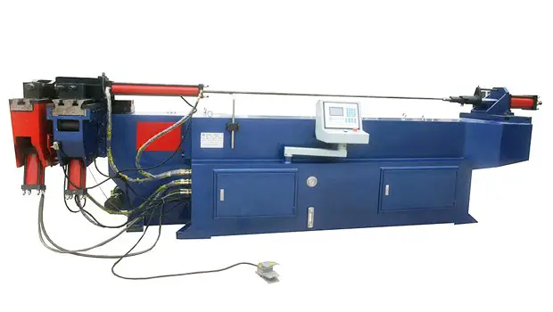
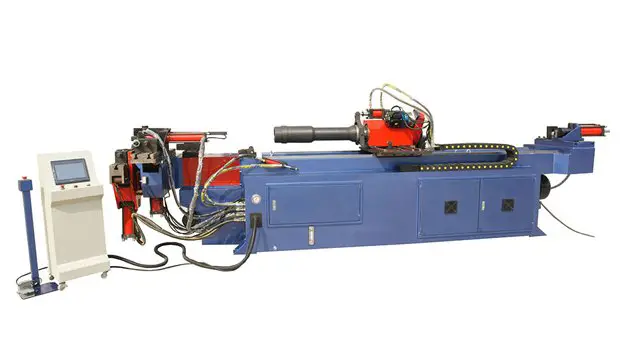
A pipe bender refers to a machine used for bending pipes, which can be classified into numerical control and hydraulic types. These machines are widely used in various industries such as power construction, railway and highway construction, bridges, ships, and more.
Unlike plate bending machines, pipe benders are mainly utilized for bending steel pipes. They are commonly used in power construction, railway construction, boilers, bridges, ships, furniture and decoration, and other pipeline laying and building applications.
Pipe benders are also considered as an important equipment in the tubing machinery industry. They offer multiple functions, have a well-designed structure, and are easy to operate.
What is Pipe Bending Machine?
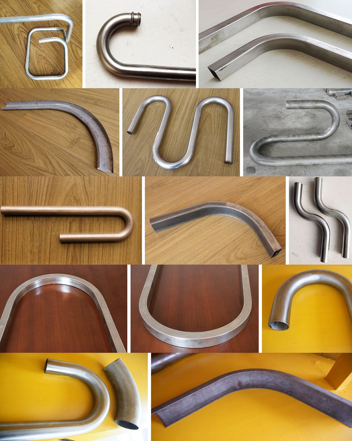
Pipe bender is a machine designed for bending pipes. It is typically used for bending hollow or solid pipes made from hard materials into various shapes, including angles and curves. This includes bending of iron pipes, steel pipes, aluminum alloy pipes, and more.
Pipe benders can be categorized into two types: CNC pipe benders and hydraulic pipe benders. They are widely used in the construction of power plants, highways and railways, pipeline laying and repair in boilers, bridges, ships, furniture, decoration and other industries.
The pipe bender has several advantages, including multiple functions, a reasonable structure, and simple operation.
Types of Pipe Benders
The pipe bender is a machine used to bend pipes into various shapes, such as I-beams, channel steels, angle irons, wires, and more. It can also form coils, “U” shaped pipes, half pipes, and coil pipes. The categories of pipe benders include hydraulic electric bending machines, horizontal hydraulic pipe benders, and multi-functional rolling pipe benders.
The electric pipe bender is powered by electricity and driven by a motor, speed changer, and gear chain transmission. On the other hand, the hydraulic pipe bender decomposes the bending operation into driving clamping to retract with hydraulic pressure, bending the pipe back, auxiliary movement forward and backward, feeding and retracting the core.
The hydraulic pipe bender is a common plane winding automatic bending machine and has the advantages of multiple functions, reasonable structure, simple operation, convenient movement, and fast installation. It is used in electric power construction, highway and railway construction, boilers, bridges, ships, furniture, decoration, and more.
The CNC pipe bender, on the other hand, uses a servo motor instead of hydraulic power and is able to control feeding and retracting, rotation of the tilting angle, pipe bending and retracting, auxiliary movement forward and backward, and head lift. The difference between the CNC pipe bender and the hydraulic pipe bender lies in the continuous production, processing precision, and three-dimensional forming of pipe fittings.
The numerical control pipe bender can perform winding bending with one or two bending radii for pipes in a cold state and is widely used in the bending of various pipe fittings and wires in industries such as automobiles and air conditioning.
There are two bending methods of the pipe bender:
1. Cold bending, including hydraulic pipe bender, electric pipe bender and three roll bending machine;
2. Hot bending, the representative model is the medium frequency pipe bender.
Working Principle of Pipe Bending Machine
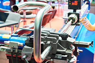
According to the method of pipe bending, it can be divided into push bending, roll bending, press bending, and circle bending. Of these, circle bending is relatively easy to automate, so currently, bending machines are mostly designed for this method. The bending process principle is illustrated in a diagram.
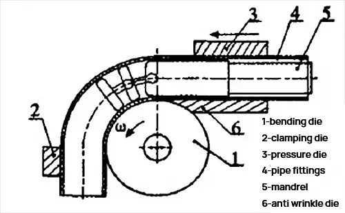
The bending process is performed using a bending die, clamping die, and pressure die. The bending die is mounted on the spindle, while the clamping die secures the pipe fittings to prevent any axial movement. The pressure die consists of a guide die and a follow-up die. During the bending process, the guide die applies the appropriate pressure on the anti-wrinkle die to the pipe fittings, and the follow-up die moves along with the pipe fittings. A mandrel is also used to fill the inner cavity of the workpiece and prevent any wrinkles, flattening, thinning or other failures during bending.
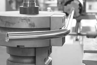
The spindle rotates and the tube is formed by being wound around the bending die. The process also involves feeding the workpiece, preparing the space for the next bend, and so on. The bending radius is determined by the radius of the bending die, and different bending radii can be achieved by simply replacing the bending die with one of a different radius.
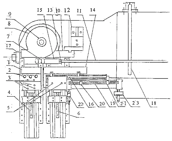
Structure and working principle of automatic pipe bender and electro-hydraulic pipe bender:
The hydraulic system of a pipe bender is composed of an electric oil pump, high-pressure oil pipes, quick connectors, working cylinder, and plunger. The elbow part of the machine includes an upper flower plate, lower flower plate, die head, and roller. The electric oil pump outputs high-pressure oil, which is sent to the working cylinder through high-pressure oil pipes. The high-pressure oil drives the plunger in the working cylinder to generate thrust, resulting in bending through the elbow component.
Features of Pipe Bender
The Pipe Bender uses a touchscreen to add a numerical control module and features a dialogue-type operation for easy program setting. Its structure is stable and not easily deformed.
Each file can store 16 bending angles, and 16 sets of files can be stored in memory. The slow-speed positioning function and stable bending angle ensure a repetition accuracy of ±0.1°.
In case of error, the message will be displayed on the screen to help the operator eliminate the issue immediately. The device also comes with research and development software for converting pipe processing values into coordinates, which can be purchased and installed on a desktop computer for editing and calculation.
Advantages & Disadvantages of Pipe Bending Machine
When using the Pipe Bender, high-pressure oil from the electric oil pump is sent into the working oil cylinder through a high-pressure oil pipe. This high-pressure oil pushes the plunger in the working oil cylinder to generate thrust, and the pipe is bent through the bending parts.
The Pipe Bender has several advantages:
- It uses a touch screen and numerical control module with a dialogue operation, making program setting simple and easy.
- The bed structure is stable and not prone to deformation.
- The mobile foot switch has three functions: automatic start, emergency stop, and emergency stop, providing high safety.
- There is the option to choose manual, semi-automatic, and full cycle functions.
- The machine head and elbow are elegantly designed, providing ideal elbow space.
- The large capacity cooling circulation system ensures stable machine operation.
- The mold is easy to replace, allowing for flexible production.
During processing, the screen of the mobile controller displays the current processing value of the elbow, and it is possible to set single step action, half cycle operation, and full cycle operation.
The pipe bender is primarily utilized for bending pipes.
This equipment is commonly employed in industries such as road construction, automobile processing, and shipbuilding.
The pipe bender boasts high stability, user-friendly operation and maintenance, low operational noise, and improved safety and environmental protection.
Parts & Functions of Pipe Bending Machine
The pipe bender is widely used in our daily lives, but many of us are unaware of its components.
Now, I will introduce you to the key components of a pipe bender.
- Fully Automatic Bed:
The bed features a channel steel welded spindle frame, with the upper and lower bearing support plates of the spindle mounted on a 15mm thick steel plate frame.
- System Component:
The hydraulic system component can utilize either commercial accessories or aircraft hydraulic accessories.
- Transmission Component:
The transmission component comprises an oil cylinder, rack, gear, and transmission shaft.
- Mold Component:
The mold component is a supportive tool made from bearing steel or coil steel, depending on the surface diameter, and is heat-treated to achieve a hardness of HRC48~52.
- Clamping Component:
The hydraulic clamping component consists of a sliding plate, rocker arm, and hydraulic cylinder. The expansion and contraction of the cylinder drives the movement of the rocker arm.
- Electrical Components.
Pipe Bender Technology
The pipe bender is comparable to sheet bending machines.
When a pipe is subjected to pure bending under external torque M, the outer wall of the neutral layer experiences tensile stress σ1 and becomes thinner, while the inner wall of the neutral layer experiences compressive stress σ1 and becomes thicker.
As a result of the combined forces F1 and F2, the cross-sectional shape of the pipe becomes approximately elliptical. If the deformation is excessive, cracks may form on the outer wall and wrinkles may appear on the inner wall.
The degree of deformation of the pipe depends on the relative bending radius (R/D) and the relative thickness (T/D) value; the smaller the R/D and T/D values, the greater the degree of deformation.
In order to maintain the quality of pipe fittings during the forming process, it is important to control the degree of deformation within acceptable limits. The bending capacity of a pipe depends not only on the material’s mechanical properties and bending method, but also on the requirements of the pipe fittings.
Forming limit of Pipe Bender
The forming limits of pipe fittings should encompass the following considerations:
The maximum elongation deformation in the lateral tensile deformation zone of the neutral layer should not exceed the plastic allowable value of the material, so as to avoid rupture.
In the inner compression deformation zone of the neutral layer, the thin-walled structure subjected to tangential compressive stress should not exceed the instability threshold, so as to prevent wrinkling.
If the fitting requires a specific degree of ellipticity, the forming limit should be controlled to produce the desired distortion.
If the pipe fittings have strength requirements for bearing internal pressure, the forming limit should be controlled to prevent excessive thinning of the wall thickness.
Pipe Bender Parts
The rocker arm serves to ensure that the bending radius of the pipe meets the required specifications, while the clamping seat limits the rebound of the steel pipe during the bending process.
The pump station is divided into two parts: high pressure and low pressure, which provide power for the operation of the guiding roller, rocker arm clamp seat, oil cylinder, push device, trolley card plate, and straightening roller.
The Guide Roller Device consists of two sets of guiding rollers, a frame, and a clamping transmission system. The opening and closing of the guide rollers is powered by hydraulic force and its purpose is to ensure the horizontal bending direction of the steel pipe in conjunction with the rocker arm.
The Driving Device provides the power source for the push device.
The Straightening Roller prevents vertical deformation during the bending process, and the use of a floating anti-ellipse fixture ensures that the steel pipe ellipse meets the required specifications after bending.
The Push Device (comprised of a car, bed, transmission shaft, and traction chain, etc.) advances the steel pipe forward, allowing it to bend under the influence of the rocker arm and guide roller.
Precautions of Pipe Bender
(1) Refer to the electric pump manual.
(2) First, screw the working cylinder into the inner thread of the square block so that the rear end of the cylinder is mounted on the support wheel.
(3) Select the die head based on the diameter of the pipe, set it in the plunger, align the two rollers with the corresponding groove toward the die head, place the appropriate size of the flower board in the hole, cover it with the upper flower board, insert the pipe into the groove, and then pull back the quick joint active end of the high-pressure tubing and set it on the work cylinder connector. Finally, tighten the oil release screws on the electric oil pump to begin the bending process.
Upon completion of the bending, loosen the oil release screw, and the plunger will automatically reset.
Remarks:
(1) Refer to the electric pump manual.
(2) Do not remove the quick connector during loading.
(3) The machine uses oil as the medium, so it is important to perform thorough cleaning and maintenance work on the oil and pipe benders to prevent blockages or leaks, which could affect its performance.
Electrohydraulic (electric pipe bender) application:
The automatic pipe bender is suitable for use in the installation and maintenance of pipes in various settings, including factories, warehouses, docks, buildings, railways, automobiles, etc.
Aside from its pipe bending capabilities, the pipe bending component (oil cylinder) can also be detached and utilized as a standalone hydraulic pipe jacking machine.
Pipe Bender Structure
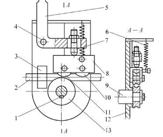
- Key
- Steel pipe
- Steel pipe Clamp
- Pin axis
- Handle
- Spring
- Adjusting Screws
- Roller seat
- Spindle
- Guide Pulley
- Rolling Press Wheel
- Turntable
- Pipe Bending Module
(1) BENDING DIE
Installation:
- remove the bending die fixed nut in the counterclockwise direction.
- put in the bending die, and then lock the bending die fixed nut.
(2) CLAMP DIE
Installation:
- pull the clamping die for fixing centering shaft.
- put the clamping die in, then insert the fixed mandrel.
Adjustment:
A. Secure and release the clamping seat, then set the control panel to manual mode. Press the clamp button to the end of the clamping path. (At this point, there should be a gap between the wheel clamping die, which can be adjusted using the clamping seat adjustment screw).
B. Adjust the clamping seat adjustment screw so that the clamping die and bending die are fully sealed.
C. Press the back button to retract the clamping die, then adjust the clamping screw by rotating it approximately 1/2 to 1/4 circle in a clockwise direction.
D. Finally, lock the fixed nut on the clamping seat.
(3) Pressure DIE
Installation:
A, remove the fixed screw on the pressure die and then put the pressure die in.
B, lock the guide mold screws.
Adjustment:
A. Secure and release the clamping seat, then set the control panel to manual mode. Press the clamp button to the end of the clamping path. (At this point, there should be a gap between the wheel clamping die, which can be adjusted using the clamping seat adjustment screw).
B. Adjust the clamping seat adjustment screw so that the clamping die and bending die are fully sealed.
C. Press the back button to retract the clamping die, then adjust the clamping screw by rotating it approximately 1/2 to 1/4 circle in a clockwise direction.
D. Finally, lock the fixed nut on the clamping seat.
(4) Mandrel
Installation:
A. put the mandrel into the core rod in the clockwise direction.
B. then fix the screws of the mandrel.
(Please note that the mandrel must be in the direction of bending)
Pipe Bender Operation
The machine tool must be properly grounded with a wire that is not less than 4mm2 in size and made of flexible copper cord. The voltage range of the power supply must not exceed the specified range, and the control circuit must not be tested with a tramegger, as this may cause damage to the device.
When inserting or removing connectors, do not pull on the wires or cables, as this may cause welding to come apart.
Limit switches, encoders, etc. must not be struck with hard objects.
Avoid collisions with sharp objects on the display unit.
The electrical box must be placed in a well-ventilated area and must not be used in dusty or corrosive gas environments.
Do not make personal modifications to the PC input and output terminals.
When changing the power supply of the machine tool, the motor must be reconfirmed.
The machine must be kept clean, with special attention paid to the clamping block and sliding block to ensure that they are free of foreign objects.
Lubricate the chain and other sliding parts on a regular basis.
The power supply must be disconnected during cleaning and maintenance.
Preparation: Before starting, check the oil level to ensure it is at the designated line, verify that all lubricating points have been attended to, and confirm the rotation of the motor. Check the oil pump for any unusual sounds and check for leaks in the hydraulic system after booting up (the angle encoder must not be lubricated during operation).
Pressure Adjustment: Use the electromagnetic overflow valve to adjust the pressure to the required working pressure, generally not higher than 12.5Mpa.
Mold Adjustment: During mold installation, it is necessary to center the mold and the clamping block, which can be adjusted using bolts. To center the boost block and die, the boost block is adjustable. To center the core head and die, loosen the core bolt, adjust the center, and then tighten the bolt.
Safety Operation Precautions of Pipe Bender
When operating the pipe bending machine, ensure that no one enters the space within the rotating arm’s sweep. All personnel must be prohibited from entering the area of the rotating arm and the pipe fittings while the machine is in operation.
The hydraulic system of the pipe bender uses YA-N32 normal hydraulic oil (designated as 20) and should have the oil changed once a year, with the filter being cleaned simultaneously.
Only authorized personnel should make adjustments to the pipe bender or die, and one person should not make adjustments alone. The other operator must be at the control cabinet.
When adjusting the pipe bender or driving an empty car, remove the mandrel.
The hydraulic system pressure must not exceed 14Mpa.
When adjusting the cylinder speed manually, the rotating arm must be rotated to over 900, and the adjustment speed must be synchronized with the linear velocity of the rotary elbow’s edge. Pushing the speed higher than the edge of the rotary mold in manual mode is prohibited.
Regularly check the tightness of the chain and keep it elastic and consistent after a certain period of time.
When using the automatic core bending mode, return the former bend arm, the operator must ensure that the core head is in the pipe or that there is no blocking of the core shaft, otherwise the core head or core rod may bend or break.
After use, cut off the power supply and properly clean and lubricate the machine.
Bend Pipe Type Regularization
Design the exhaust pipe to avoid large circular arcs, arbitrary curves, and composite bends where the circular arc exceeds 180°.
Large circular arcs not only increase the workload but also are limited by the size of the tube bender.
Unreasonable designs of arbitrary curves and composite bends hinder mechanization and automation, making it difficult for operators to relieve themselves from heavy manual labor.
An arc greater than 180° makes it impossible for the pipe bender to discharge.
Bending Speed of Pipe Bending Machine
The main effect of bending forming velocity on the forming quality is:
If the speed is too fast, it is easy to cause flat spots on the curved parts of the ducts, and the roundness may not meet the requirements, resulting in lacing and breaking of the ducts.
If the speed is too slow, it is easy to cause wrinkling of the catheter and the sliding of the pressing block, and the big pipe may form the ducted part of the sink.
To determine the maximum bending speed of the machine, the best final bending speed should be 20-40% of the maximum bending speed of the pipe bender.
The Standardization of Bending Radius of The Pipe Bender
The bending radius should be chosen to achieve both “one pipe and one die” and “multiple pipes and one die”.
When a pipe has only a few bending positions or several bending angles, there can be only one bending radius because the module of the pipe bending machine cannot be changed during the bending process. This is known as “one pipe corresponding to one die”.
However, when using “one die for multiple pipes,” pipes with the same diameter should use the same bending radius, and the same modules should be used for bending pipes with different shapes. This helps to reduce the number of modules needed.
Bend Pipe Mandrel and Its Position
In the bending process, a mandrel is used to support the inner wall of the pipe bending radius and prevent its deformation. Without the mandrel, it is difficult to guarantee the quality of pipe bending.
There are many types of mandrels, including cylindrical mandrels, universal single head, double head, triple head, and four-ball head mandrels, as well as orientation single and multi-ball head mandrels.
The position of the mandrel in the pipe forming process has a certain influence. In theory, the mandrel tangent should be at the same level as the pipe bending die tangent. However, a large number of experiments have shown that advancing the mandrel 1-2 mm is better, and the bending quality is ideal at this point.
Of course, if the mandrel is moved too much, it may cause the so-called “goosehead” on the outer wall of the curved part.
How to Install the Mould of Automatic CNC Pipe Bender?
- clamping die adjusting screw
- mandrel rod beads
- anti wrinkle plate
- mandrel rod fixing nut
- guide mold base
- auxiliary pushing limit sliding seat groove plate
- auxiliary push speed regulating valve
- set screw of pressing die sleeve
- bending die
- mandrel rod
- guide mold
- stopper seat
- auxiliary pushing front limit
- auxiliary push pressure gauge
- adjusting screw of pressing die sleeve
- bend mold locking and cap
- anti wrinkle plate seat
- mandrel
- holding bar
- auxiliary push back limit
Lock the bending die and cap (9) in a clockwise direction, loosen and remove it. After replacing the required bending wheel die, lock the bending die and cap.
Installation of main clamping die
To replace the required clamping die, first, remove the pin shaft (2) of the main clamping die, replace it with the desired clamping die, and insert the pin shaft. Next, loosen the fixing bolt (3) of the clamping die base, operate the main clamp clamping using the manual mode screen, rotate the clamping die adjusting screw (4), and move it forward until the clamping die is clamped to the bending die. Then, press the main clamp to release the clamp and rotate the clamping die adjusting screw forward for 1/3 or 1/2 turn. Finally, lock the fixing screws of the clamping die base.
Installation of guide clamping die
To install the guide die, follow the same method as above, but adjust the clamping force to be slightly looser than that of the main clamping die.
If the pipe becomes wrinkled during bending, move the adjusting screw of the pressing die sleeve forward about 1/4 turn and then try bending again until there are no wrinkles.
During the bending test, it is important to ensure that the advance speed of the auxiliary pushing is synchronized with the bending speed.
Installation and adjustment of mandrel rod and mandrel cylinder seat
To install the mandrel bead (7), screw the mandrel rod (11) into the mandrel rod (15), and connect the mandrel to the cross joint of the mandrel cylinder.
The general adjustment method is to ensure that the front end of the mandrel rod exceeds the central tangent point of the bending die by 2-5mm (depending on the diameter of the bending die; the larger the diameter, the longer the distance beyond the tangent point, and the smaller the diameter, the opposite).
The mandrel cylinder seat should be installed on the guide rail of the mandrel cylinder, and the guide rail of the mandrel cylinder should be equipped with a scale.
The pointer indicates the radius of the bending die, so if the bending die is replaced, the mandrel cylinder seat should be adjusted accordingly.
Installation of anti wrinkle device
The wrinkle-resistant plate (10) is fixed on the wrinkle-resistant seat (12), with the arc seat of the wrinkle-resistant plate close to the bending die (8). The front end should be as close as possible to the center of the wheel die, and the rear end of the wrinkle-resistant plate should be parallel to the guide die with a difference of 1-2 degrees to reduce friction between the wrinkle-resistant plate and the workpiece.
Handling and Installation of Pipe Bender
Handling:
The entire machine tool can be lifted by threading steel wire through the bottom of the machine tool.
Cotton yarn or cloth should be placed at the contact point between the steel wire rope and the machine tool to avoid damaging the machine body surface.
During handling, the moving parts should be secured to prevent movement and collisions.
Installation:
The machine tool should be installed directly, and the equipment level can be adjusted by adjusting the damping sizing block at the foot of the machine tool.
The position of the oil cooler relative to the machine tool should be determined according to the actual operating position.
Preparation for commissioning:
- Before starting up, the operator should carefully read the instructions and be familiar with the safety precautions, performance, and operating specifications of the machine tool.
- Connect the cable between the operation box and the host.
- Add hydraulic oil to the hydraulic oil tank up to the centerline of the oil level indicator.
- Add No. 20 mechanical oil to the revolving body and gearbox up to the centerline of the oil level indicator.
- Inject lubricating grease into the sliding block of the linear guide rail and various oil cups.
- Check whether there is any foreign matter on and around the motion track of the moving parts.
- After the power supply is connected, press the hydraulic motor start button (motor) and quickly press the emergency stop button (fstop), and observe whether the motor’s direction conforms to the direction mark. If not, adjust the power wiring and try again.
- Check the pressure of the hydraulic system (after the hydraulic motor is started, press the electromagnetic overflow valve core with the help of appropriate tools), and the indicated value on the pressure gauge should be less than 14 MPa (generally adjusted when leaving the factory).
Applications of Pipe Bending Machine
Application of pipe bender in power generation equipment manufacturing industry:
Under the background of increasingly tight global resource supply and rising oil prices, the demand for power generation equipment has become more and more obvious.
In the manufacturing process of power generation equipment, the cost spent only on the CNC pipe bender is very considerable.
Application of pipe bending machine in mold manufacturing industry:
In the process of pipe bender mold manufacturing, NC pipe bender mold is used in almost all links, such as forming mold, hot mold, cold mold, plastic mold, etc.
In addition, automobile, adjustment train, general machinery manufacturing, and furniture manufacturing have become the main users of CNC pipe bender mold industry.
Application of pipe bender in aerospace industry:
In this industry, pipe benders are generally used to bend aircraft structural parts; these structural parts are generally large in volume, and aluminum alloy was widely used in the past.
With the expansion of the application fields of titanium alloy and composite metal materials, the requirements for NC pipe bending machine are becoming higher and higher.
What is The Price of Pipe Bending Machine?
The configuration of the hydraulic pipe bender plays an important role in determining the price. There is a saying that the price is equal to the goods. Each price has its own reasons and requirements.
Users who require high bending accuracy and efficiency of the hydraulic pipe bender are very concerned about the quality. The quality is determined by the internal configuration of the equipment.
For some customers, they are very concerned about the price, but they also have certain requirements for quality. It is challenging to balance the trade-offs between them.
Currently, most of the pipe benders in the market range from 3000 to 100,000 RMB, and the specific quotation depends on the wall thickness and bending radius of the material.
How to Use Pipe Bending Machine?
Adjustment of machine tool:
To achieve the desired geometric shape for the bent pipe, select the mold based on the pipe fitting’s outer diameter, wall thickness, and bending radius, and then adjust the corresponding parts.
- Bending angle:
Enter the required angle on the operation display screen according to the user’s needs (refer to the electrical appliance manual).
- Adjustment of clamping and boosting sliding plate mechanism:
The pipe clamping and boosting of this machine tool adopts a connecting rod force-increasing mechanism.
To ensure the self-locking of the clamping state, first loosen the screw rods of the pipe clamp mechanism and the booster mechanism. Then, under the manual state, the two mechanisms are in the clamping position, and finally, tighten the screw rods.
The speed of the sliding block can be adjusted by the one-way throttle valve to synchronize it with the main shaft.
- Adjust the rotation part of the traverse screw rod based on the selected pipe and mold to make its sleeve center line coincide with the center of the mold elbow.
- Tailstock adjustment:
First, adjust the tailstock so that the center of the core rod coincides with the center of the die elbow, and then adjust the screw rod on the piston rod of the tailstock so that the core head extends to the appropriate position.
Idling of machine tool:
- In manual mode, press the action button to drive the corresponding oil cylinder and observe whether the action is normal without crawling, pulsation, and oil leakage.
- Use the inching mode to move the trolley along the guide rail, rotate the rotary sleeve, and observe its flexibility and accuracy.
- Drive the collet clamping cylinder to observe the movement of its sliding sleeve and the reliability of the clamping.
- Select several different angles to observe the coordination and consistency of the actions of each mechanism in automatic mode. After verifying that all items are normal, the equipment can be put into normal use.
Tips for Using Pipe Bending Machine
The following points should be paid attention to after purchasing the pipe bender:
Before operating, please check whether the machine’s lubricating points are short of oil, whether the safety protection device is reliable, and whether the moving mechanism is loose. One person should confirm before starting the operation.
Start the elbow oil pump and check whether the system pressure is within the specified range. If the pressure is too high, it may damage the hydraulic components and waste power. If it is too low, it will affect the work.
Adjust the required position and angle of the parts, and position the parts to the required length.
Adjust the vertical lifting guide rail so that the die pressing cylinder can clamp the iron pipe tightly.
Ensure that the clamping die pressing cylinder can clamp the iron pipe.
During normal operation, put the workpiece into the bending die, contact and position the front end, and press the foot switch to complete.
After completing the work, cut off the power supply and perform proper cleaning and lubrication.
In case of an emergency when operating the pipe bender, press the emergency stop button, turn the twist switch to the manual position, and reset it manually. In case of failure, please report for repair in a timely manner.
Maintenance of Pipe Bending Machine
Eight methods for pipe bender maintenance:
Method 1:
When operating the pipe bender, it must be strictly operated in accordance with the operating regulations (key points).
Regular maintenance of the machinery is necessary. The maintenance personnel must be qualified through education and training.
Method 2:
The pipe bender must be kept clean, and the unpainted parts should be coated with anti-rust grease.
Check whether the pressure of each oil pressure system is normal.
Method 3:
Before starting the pipe bender each time, lubricating oil should be added regularly at fixed points and quantitatively according to the requirements of the lubrication chart.
The oil must be clean and free of sediment.
The oil pipe and line of the bending arm should not touch the ground.
Method 4:
Regularly check and repair the switch, fuse, and handle to ensure their reliable operation.
Regularly check that the hydraulic oil in the oil tank reaches at least 80% of the oil level gauge.
Method 5:
The lubricating oil in the motor bearing shall be replaced and filled regularly, and the operation of the motor shall be checked regularly.
The temperature index of the oil level gauge should not exceed 60℃.
Method 6:
Regularly check whether the V-belt, handle, knob, and key are damaged. If they are significantly worn, they should be replaced promptly.
Regularly add lubricating grease at the meshing position between the transmission gear and the rack.
Method 7:
It is strictly prohibited for non-designated personnel to operate the equipment. In general, people must leave the machine and stop.
The sliding part or rotating part must be regularly lubricated.
Method 8:
Lubricate and clean the pipe bender 10 minutes before work every day.
When operating below 5℃, pay attention to the ponding and do not let it freeze.
Do not place magnetic objects near the servo motor or knock them.
When cleaning the LCD, please cut off the power first, and do not clean it with liquid detergent or liquefied vapor.
Do not place the machine in a location where there is rain leakage or humidity.
Troubleshooting of Pipe Bending Machine
If oil leakage is found at the oil cylinder, confirm the need to replace the sealing ring.
If the machine pressure is found to be insufficient, please check whether the oil level in the oil tank is sufficient and whether the oil temperature is too high.
When the proximity switch is not sensed, the display screen will show the corresponding cause of the fault. Use the displayed fault information to locate the problem for maintenance and troubleshooting.
In case of an inaccurate angle, please check whether the claw cylinder moves forward and is in place, or check whether the corresponding claw is too large.
If the servo does not turn or the servo motor does not feed during operation, please check whether there is a fault code in the servo driver. The most common fault is a momentary low voltage. If experiencing the above conditions, turn off the main power supply first and restart it after 30 seconds. If it cannot be solved, please notify the company. Do not disassemble and repair without authorization, as you will be responsible for the consequences.
If the bending angle is not correct, please check whether the fixing screw of the encoder coupling is loose and whether the end slow bending has an input angle.
If any action of oil pressure fails to respond, please check whether the corresponding solenoid valve is abnormal.
Best Pipe Bending Machine Suppliers/Manufacturers
You can read the Top 16 Pipe and Tube Bending Machine Manufacturers to learn more details.
How to Choose the Right Pipe Bending Machine?
First, the pipe diameter range of the elbow must be determined according to the actual production situation.
Some hardware processing plants use pipe benders for various pipe fittings, but each pipe bender has its own limitations, and its bending capacity is limited by its own parameters.
Second, it is necessary to determine the bending parameters of the largest pipe fitting that falls within the scope of bending, including:
- Material of pipe fittings (steel pipe, stainless steel pipe, aluminum pipe, etc.)
- Pipe section (round pipe, square pipe, angle iron, etc.)
- Outer diameter of pipe
- Pipe wall thickness
- Bending radius (referring to pipe pitch diameter) and other parameters.
Finally, provide the manufacturers with these parameters. They will typically recommend the model you need based on your parameters.

Thanks for sharing such useful information : )
how to design a bending die