Have you ever wondered about the unsung heroes of industrial processes? In this blog post, we’ll dive into the fascinating world of heat exchangers, the essential devices that quietly keep our machines running smoothly. As a seasoned mechanical engineer, I’ll guide you through the various types of heat exchangers, their unique characteristics, and how they efficiently transfer heat between fluids. Get ready to discover the ingenious designs that make our modern world possible!
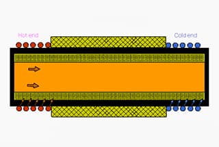
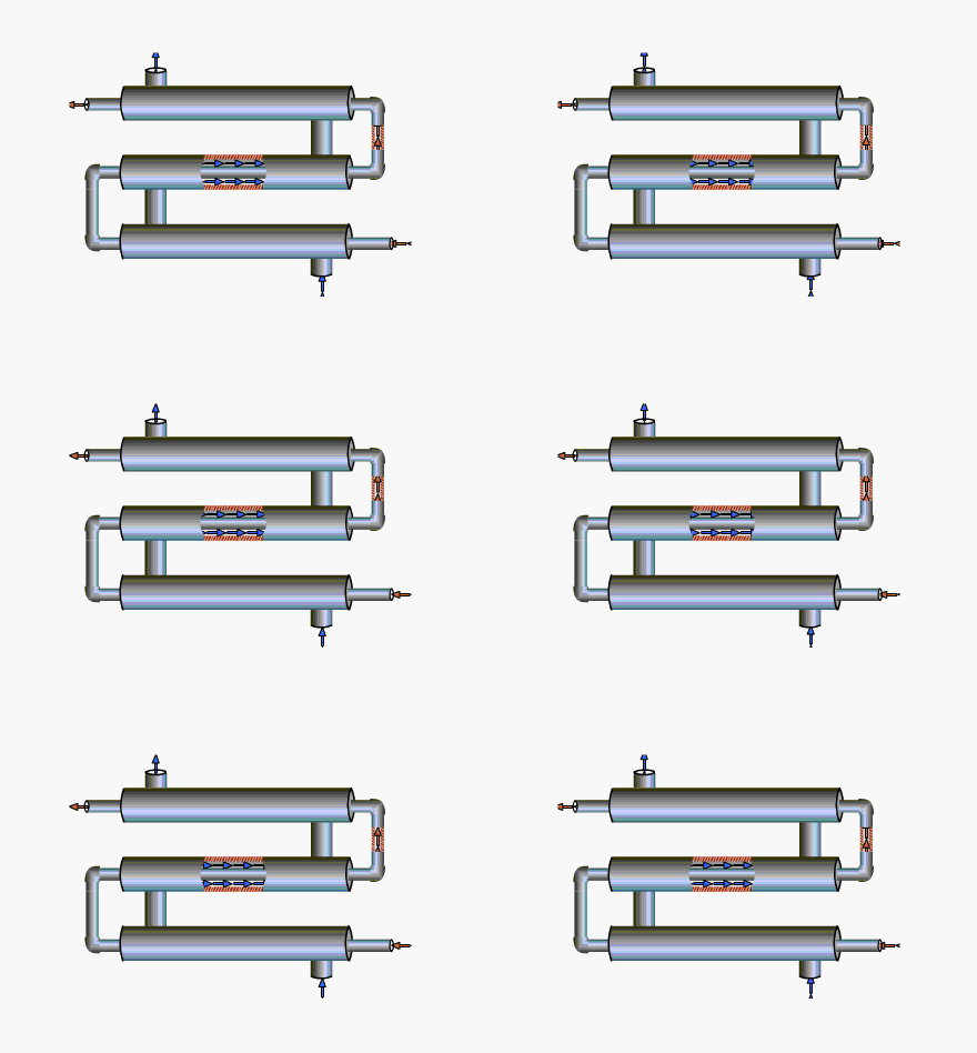
Each segment of casing is referred to as a “single pass”. The inner tube (heat transfer tube) of the pass is connected by U-shaped elbow tubes, while the outer tube is connected in rows with short tubes and fixed on the support. Heat is transferred from one fluid to another through the wall of the inner tube. Typically, the hot fluid (Fluid A) is introduced from the upper section, and the cold fluid (Fluid B) is introduced from the lower section. Both ends of the outer pipe of the casing are connected to the inner pipe through welding or flanges. The inner tube and U-shaped elbow tube are connected by flanges, making it easy to clean and increase or decrease heat transfer tubes. The effective length of each heat transfer tube is 4 to 7 meters. The heat transfer area of this heat exchanger can reach up to 18 square meters, making it suitable for small-scale heat exchange.
It has a simple structure and can withstand high pressure, making it suitable for various applications. Additionally, the heat transfer area can be easily adjusted to meet different needs.
There are numerous joints between the pipes which are prone to leakage. Additionally, it occupies a significant amount of space and requires a substantial amount of metal per unit of heat transfer surface.
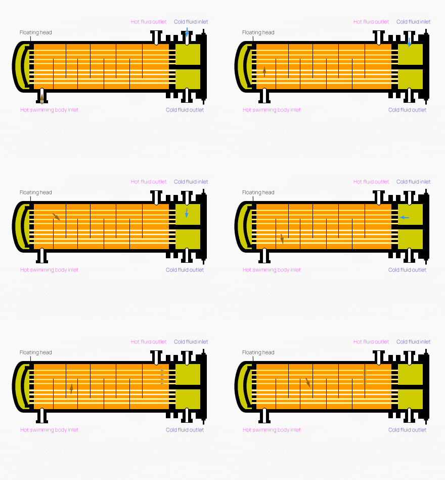
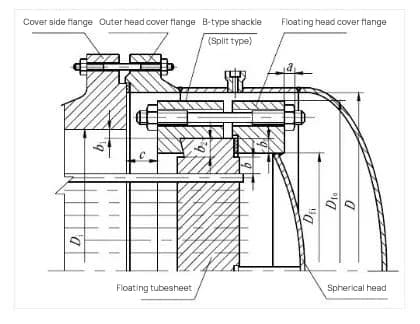
The structure of a floating head heat exchanger consists of a cylinder, an outer head cover side flange, a floating head tube plate, a hook ring, a floating head cover, an outer head cover, screw holes, a steel ring, and more. The design of the hook and loop floating head is depicted in the accompanying illustration.
When there’s a temperature difference between the heat exchange tube and the casing, the casing or heat exchange tube won’t inhibit each other and won’t create temperature difference stress. The bundle of tubes can be taken out of the casing to make it easier to clean inside and between the tubes.
The structure is complex, resulting in a high amount of materials and cost. If the seal between the floating head cover and the floating tube plate is not tight, it can cause internal leakage, leading to the mixing of the two media.
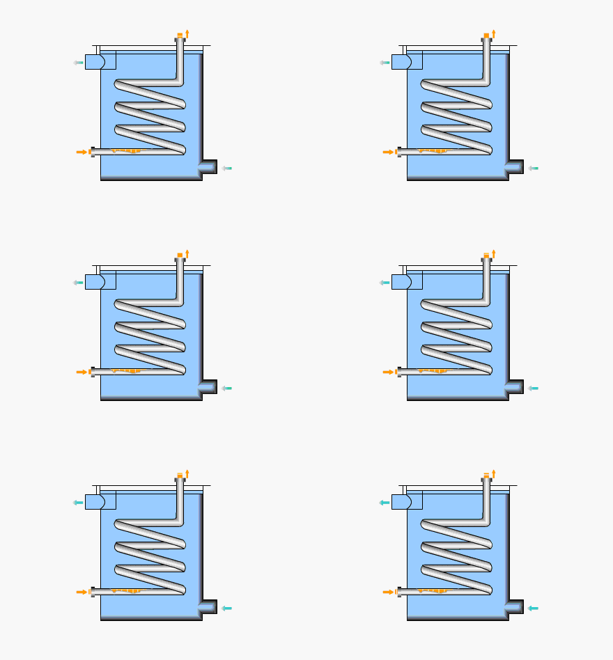
This type of heat exchanger shapes metal tubes into various forms suitable for the container, and immerses them in the liquid inside the container.
It has a simple structure and can withstand high pressure, and it can also be made of corrosion-resistant materials.
The degree of turbulence in the liquid in the container is low, and the heat transfer coefficient on the outside of the tube is small. To improve the heat transfer coefficient, an agitator can be installed in the container.
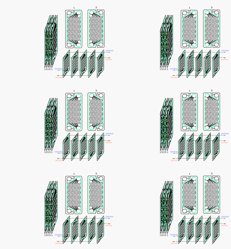
The Plate Heat Exchanger is an ideal piece of equipment for conducting heat exchange between liquids and between a liquid and a vapor. It is a highly efficient heat exchanger made up of a series of corrugated metal sheets.
The structural principle of the Plate Heat Exchanger consists of multiple corrugated sheets pressed together at a fixed interval, sealed with gaskets, and held in place by frames and compression screws. The four corners of the plates and gaskets form the distribution and collection pipes for the fluid. The cold and hot fluids are separated and flow through the flow channels on both sides of each plate, where heat exchange takes place through the plates.
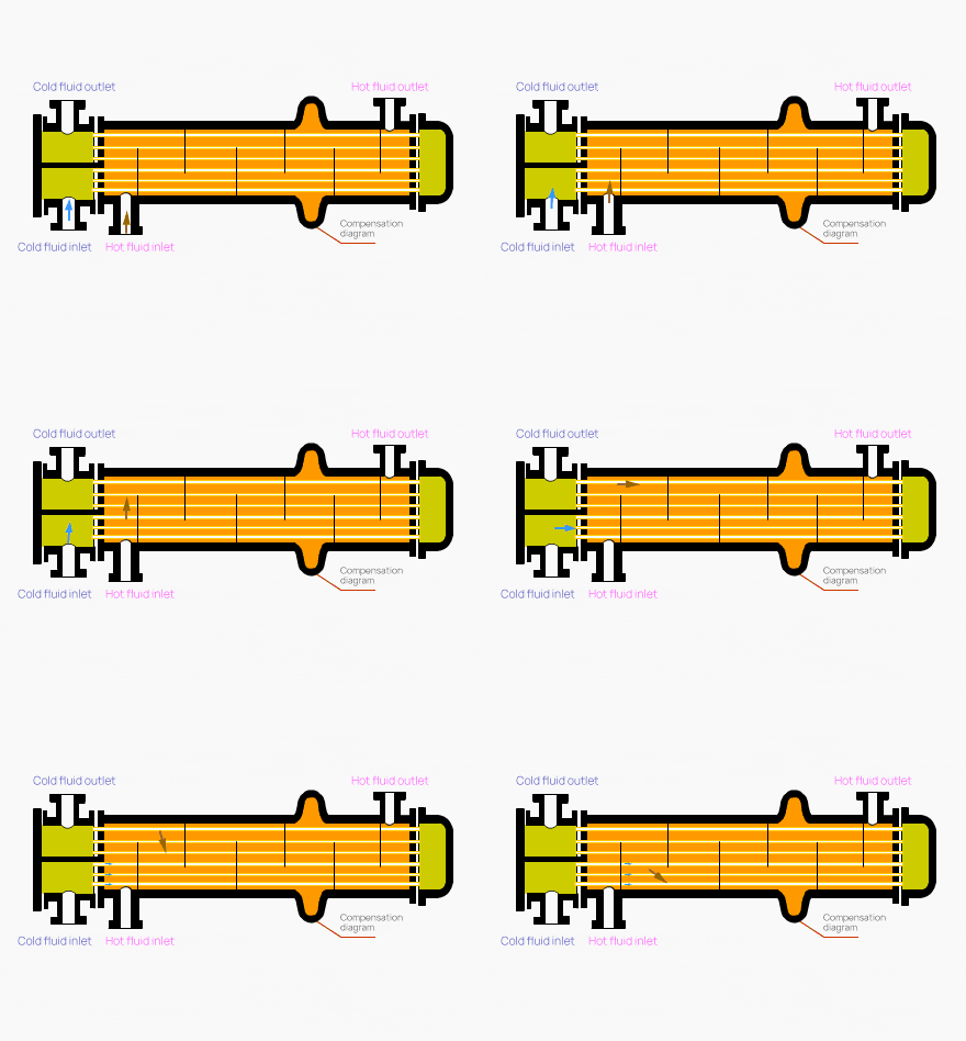
The heat exchanger is composed of a baffle, a compensation ring, and a heat release nozzle. When the fluid exchanges heat at a high temperature, the compensation ring eliminates the thermal stress caused by the large temperature difference between the shell and the tube bundle, which results from different thermal expansion rates.
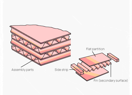
The plate fin heat exchanger is an efficient, compact, and lightweight heat transfer device. In the past, its high manufacturing cost limited its use to a few industries, such as aerospace, electronics, and atomic energy. However, it has gradually been adopted in the petrochemical and other industrial sectors. There are various structural forms of plate fin heat exchangers, but the basic elements remain the same: two parallel thin metal plates with corrugated or shaped metal fins added in between to seal the sides, forming a basic unit of heat exchange.
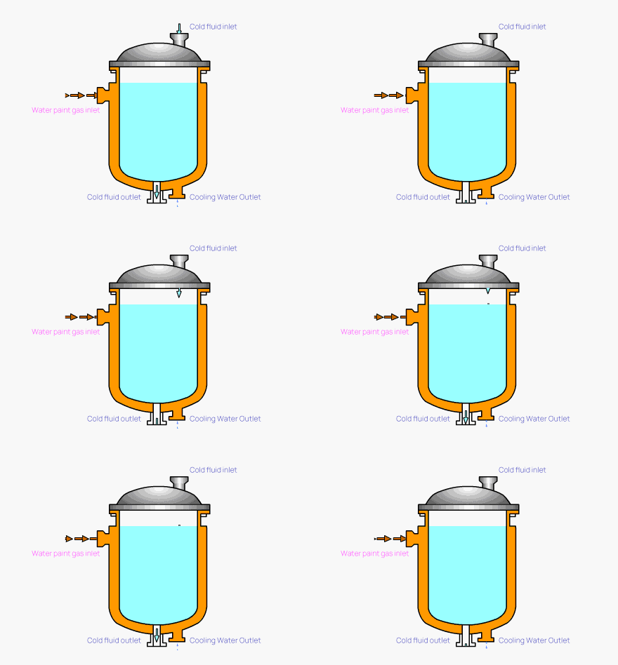
A jacket is installed on the outer wall of the container, creating a space between the jacket and the container that serves as a path for heating or cooling medium. However, the heat transfer surface is limited by the wall of the vessel, resulting in a low heat transfer coefficient. To improve the coefficient and ensure even heating of the liquid in the container, an agitator can be installed. Additionally, spiral baffles or other turbulence-increasing measures can be set in the jacket when cooling water or heating agents without phase change are introduced, further enhancing the heat transfer coefficient on one side of the jacket.
Simple structure and convenient processing.
Small heat transfer area and low heat transfer efficiency.
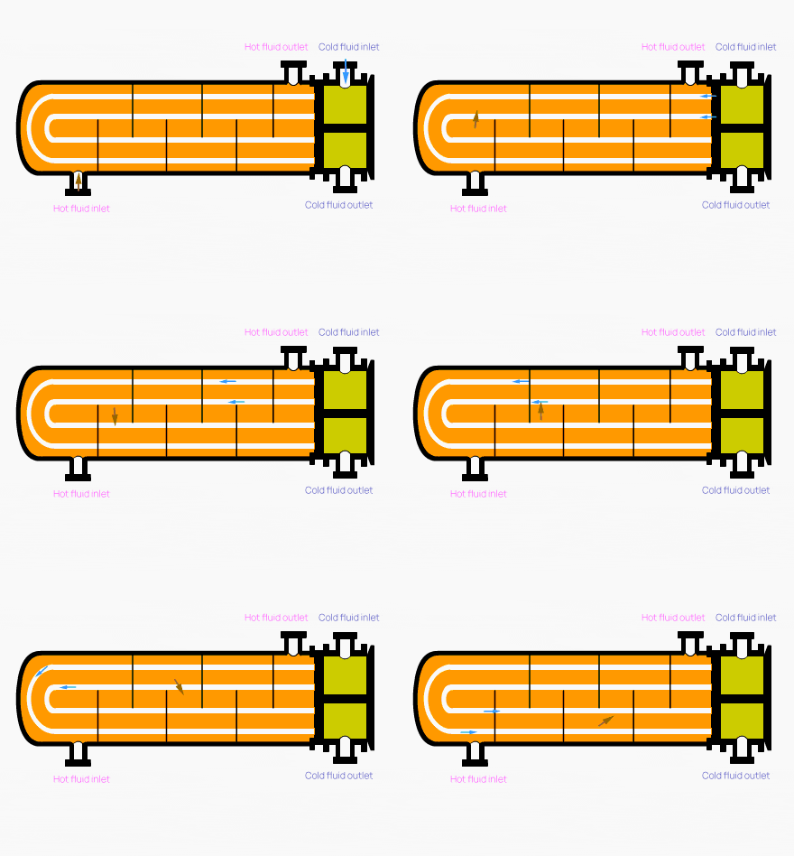
The U-shaped tube heat exchanger is composed of heat exchange tubes that are bent into a U shape, with both ends fixed on the same tube plate. The shell and heat exchange tubes are separate, allowing the tube bundle to expand and contract freely without generating temperature difference stress. This heat exchanger has a simple structure, with only one tube plate and no floating head. The tube bundle can be easily extracted and installed for cleaning, making it convenient to use.
However, the U-shape of the tubes with different bending radii means that only the outermost heat exchange tube can be replaced if damaged, while the others must be blocked. Additionally, the gap in the center of the tube bundle caused by the limited bending radius of the heat exchange tubes can result in fluid short-circuiting, affecting the heat transfer performance.
The advantages of a U-shaped tube heat exchanger include:
The structure is simple, with only one tube plate, fewer sealing surfaces, ensuring reliable operation and low cost. The tube bundle can be easily removed for convenient cleaning between tubes.
The pipe is difficult to clean;
Due to the requirement for a certain bending radius, the utilization rate of the tube sheet is low;
The spacing between the innermost tubes in the tube bundle is large, causing potential for short-circuiting in the shell side;
If the inner pipe breaks, it cannot be replaced and must be blocked, leading to a high scrap rate.
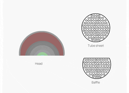
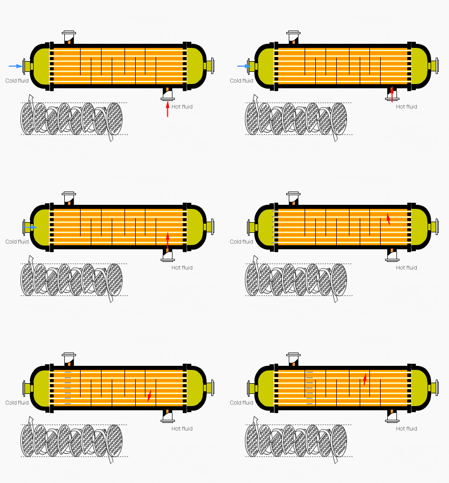
Tubular heat exchanger is currently the most widely used type of heat exchanger in the chemical industry and alcohol production. It consists of components such as a shell, tube sheet, heat exchange tubes, head, and baffle. The materials used can be made of ordinary carbon steel, red copper, or stainless steel.
In the heat exchange process, one fluid enters through a connecting pipe in the head, flows through the tubes, and exits through the outlet pipe at the opposite end of the head, referred to as the tube-side.
Meanwhile, another fluid enters through a connecting pipe in the shell and exits through another connecting pipe, referred to as the shell-side in a tubular heat exchanger.
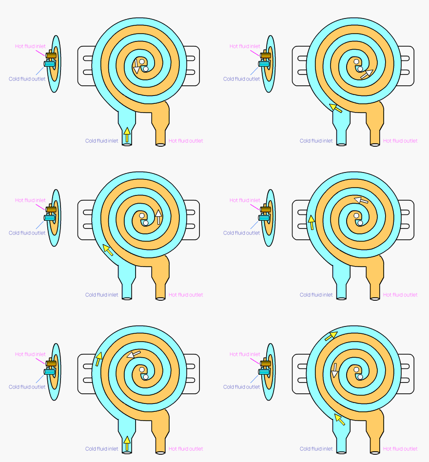
The Spiral Plate heat exchanger is a new, efficient, and stable heat exchanging equipment that can function well in conjunction with multiple units. It boasts high heat transfer efficiency and strong operation reliability, with low resistance.
However, the Spiral Plate heat exchanger requires high-quality welding and can be difficult to repair. Also, due to its heavy weight and poor rigidity, extra caution should be exercised during transportation and installation.
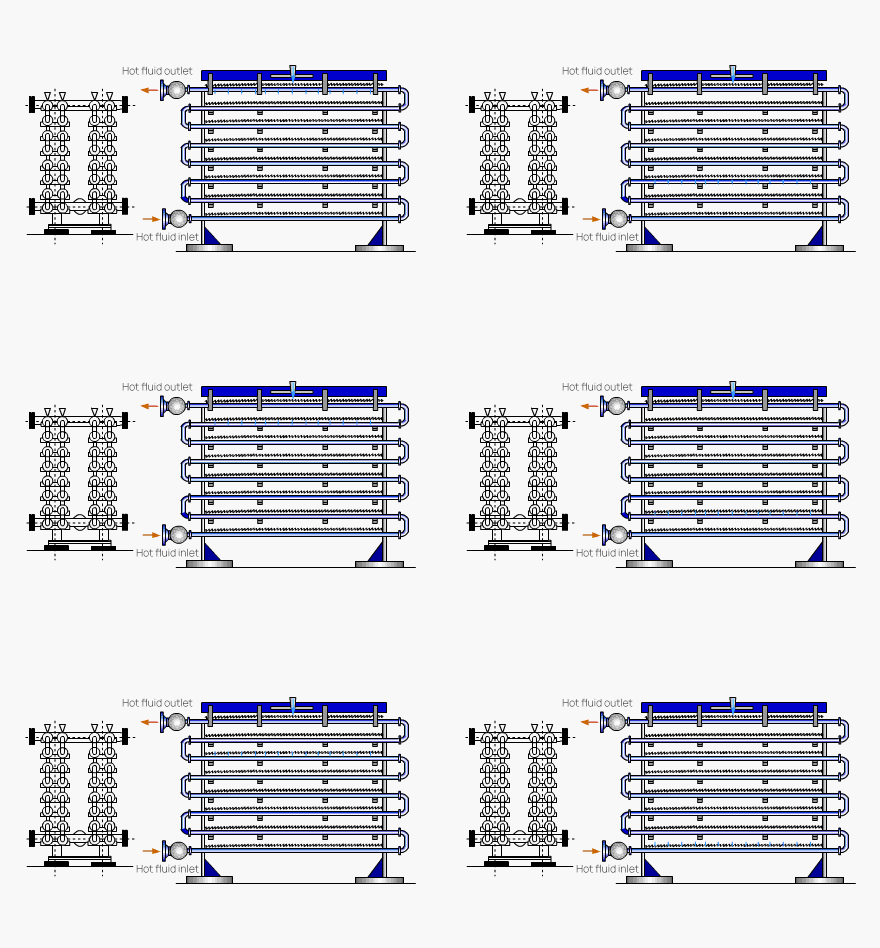
This type of heat exchanger involves fixing heat exchange tubes in rows on a steel frame. The hot fluid flows within the tubes, while cooling water is evenly distributed from the spray device above. It is also known as a spray cooler.
The heat transfer coefficient outside the tube is significantly larger than that of an immersion-type heat exchanger due to the presence of a layer of high-turbulence liquid film outside the tube. Additionally, these heat exchangers are often placed in areas with air circulation, and the evaporation of the cooling water also removes some of the heat, which helps to lower the temperature of the cooling water and boost the heat transfer driving force.
Therefore, the spray type heat exchanger has a much-improved heat transfer effect compared to immersion type heat exchangers.
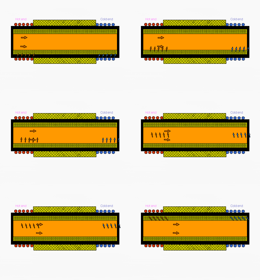
Heat pipes are a type of heat transfer component with high thermal conductivity. They transfer heat through the evaporation and condensation of the working medium in a fully enclosed vacuum shell.
They have many advantages, such as high thermal conductivity, good isothermal behavior, the ability to change the heat transfer area on both the hot and cold sides, long-distance heat transfer, temperature control, and more.
However, the drawback is poor oxidation resistance and high temperature resistance. This can be addressed by installing a ceramic heat exchanger in front, which resolves the issue of high temperature resistance and corrosion resistance.
Currently, heat pipes are widely used in industries such as metallurgy, chemical, oil refining, boilers, ceramics, transportation, light textiles, machinery, and others. As a means of recovering waste heat and utilizing thermal energy in the process, heat pipes have shown remarkable economic benefits.

