What makes hobs so crucial in gear manufacturing? This article explores nine different types of hobs, detailing their unique features and applications in machining. From gear hobs to specialized tooth profiles, discover how each type enhances precision and efficiency in gear production. By reading, you’ll gain insights into the specific uses and benefits of various hobs, aiding in your understanding of their role in modern manufacturing.
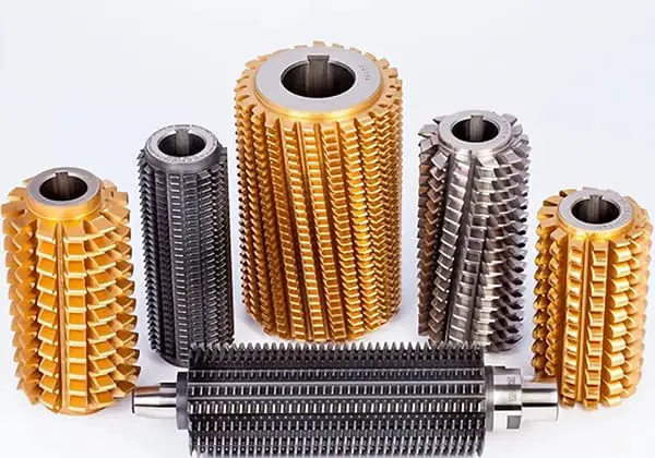
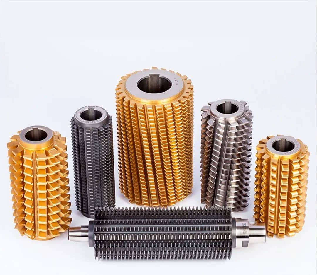
Gear hobs are precision cutting tools essential for manufacturing high-quality spur and helical gears. These versatile tools excel in various finishing operations, including pre-shaving and pre-grinding, and can accommodate a wide range of gear profiles such as convex corners, half-top teeth, and top cutting configurations.
Hobs are available in two primary designs: those with a central bore (hole type) and those with an integral shank (rod type). They can be manufactured as single-start or multiple-start configurations, with the latter offering increased productivity for certain applications. The accuracy grades typically span from A to AAA, with AAA representing the highest level of precision.
Furthermore, hobs are categorized based on their cutting environment: dry cutting hobs, designed for use without coolant, and wet cutting hobs, optimized for use with cutting fluids. The choice between these types depends on factors such as workpiece material, cutting parameters, and desired surface finish.
Regarding specifications, gear hobs cover a broad range of sizes and configurations. The modulus range generally extends from 0.25 to 33, catering to both fine-pitch and large-scale gear production. For imperial measurements, the diametral pitch (DP) control range spans from 0.75 DP to 100 DP, accommodating a wide spectrum of gear sizes. The maximum hob diameter and length are 330mm and 380mm, respectively, allowing for the production of gears with substantial dimensions.
Accuracy classifications are determined in accordance with international standards such as DIN (German Institute for Standardization) and GB (Chinese National Standards), with grades ranging from A to AAA. The AAA classification denotes the highest level of precision, suitable for applications demanding exceptional gear quality and performance.
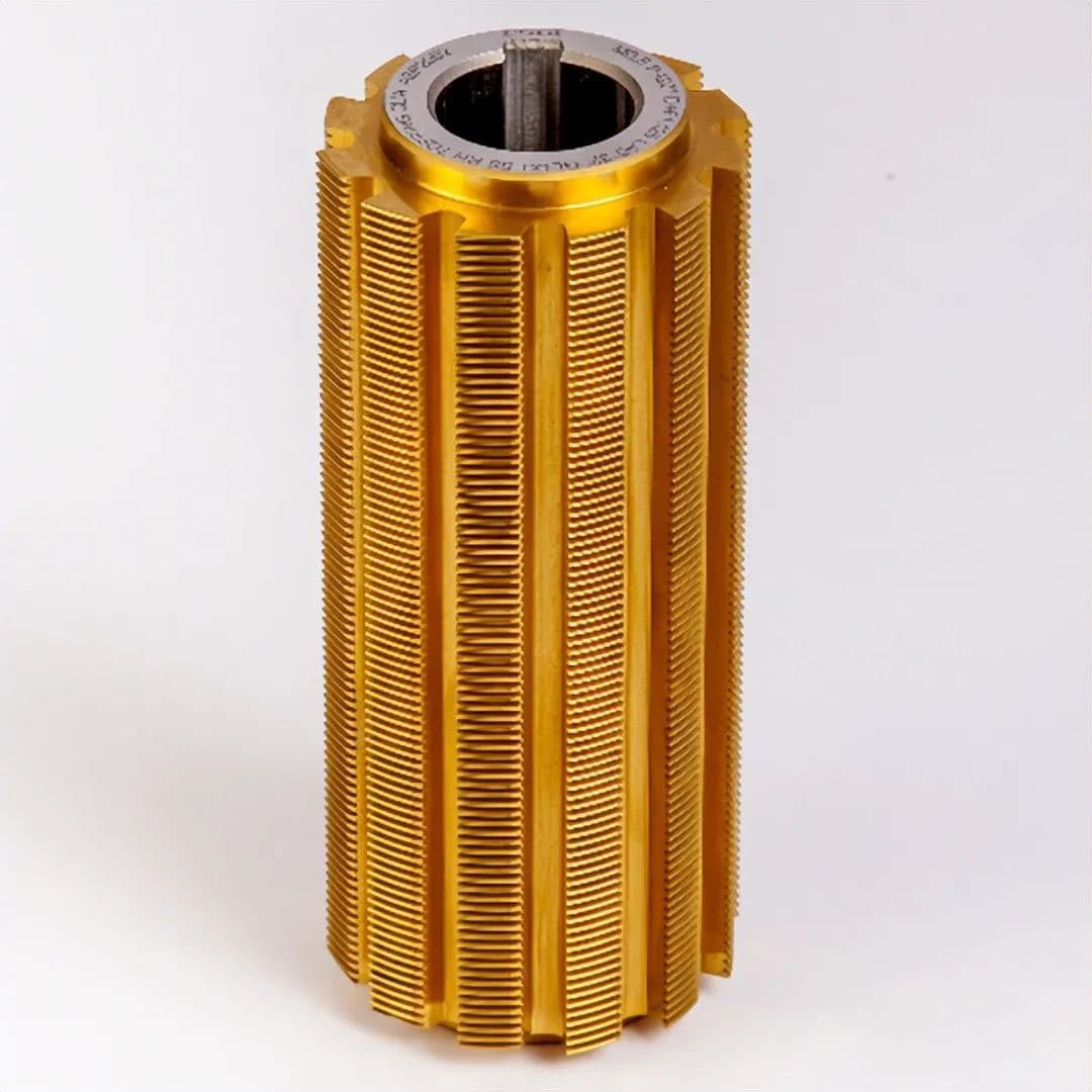
Involute spline hobs are precision cutting tools essential for manufacturing high-quality splined shafts and internal splines. The most widely adopted involute spline standards in the global manufacturing industry include:
Each standard defines specific parameters such as pressure angle, module, number of teeth, and dimensional tolerances. When selecting or designing involute spline hobs, engineers must consider factors like the required spline profile accuracy, material properties, production volume, and compatibility with existing equipment. Modern CNC hobbing machines, coupled with advanced coating technologies for hob cutters (e.g., TiAlN, AlCrN), have significantly enhanced the efficiency and precision of involute spline manufacturing processes.
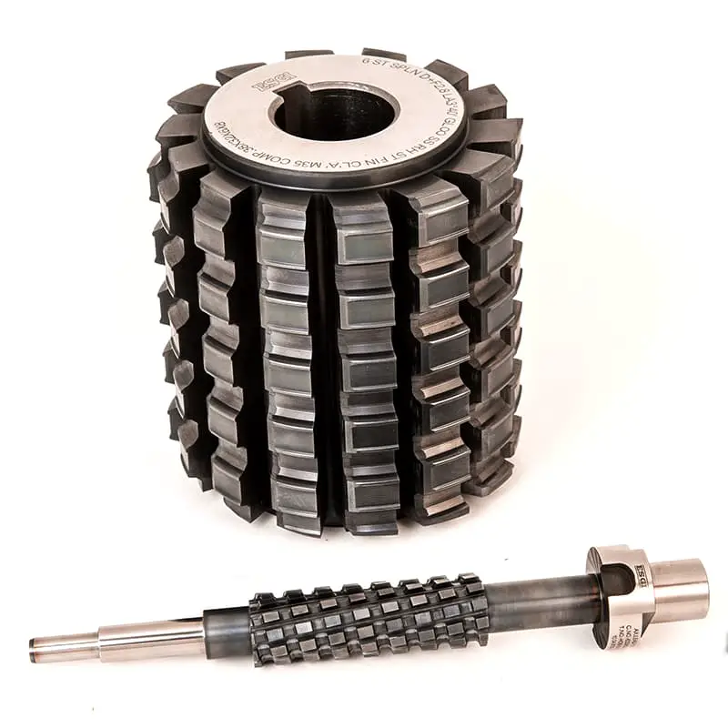
The production of hobs for parallel side splines adheres to a comprehensive set of international and national standards, ensuring precision, interchangeability, and quality across various industrial applications. These standards include:
1. DIN (Deutsches Institut für Normung) standards:
2. ISO (International Organization for Standardization) standard:
3. UNI (Ente Nazionale Italiano di Unificazione) standards:
4. GB/T (Guobiao standards) standard:
These standards govern various aspects of hob design and manufacturing for parallel side splines, including geometry, dimensions, tolerances, inspection methods, and quality control procedures. Adherence to these standards ensures global compatibility, facilitates international trade, and maintains consistent performance across different manufacturing environments.
When selecting or designing hobs for parallel side splines, engineers and manufacturers must consider the specific requirements of their application and choose the appropriate standard to follow. This selection process involves factors such as load capacity, operating conditions, mating component specifications, and industry-specific requirements.
| Type | Characteristic | Application |
|
Rectangular spline (GB/T1144-1987)  | The spline connection is multi tooth work, with high bearing capacity, good centricity and guidance, shallow tooth root, less stress concentration, and less strength weakening of shaft and hub.Rectangular spline is easy to process and can obtain high precision by grinding.Two series are specified in the standard: light series for static connection with light load, and medium series for medium cutting load.The tooth profile of involute spline is involute, and there is radial force on the tooth when it is loaded, which can play the role of automatic centering, so that the force on each tooth is uniform, with high strength and long service life.The processing technology is the same as that of gear, and it is easy to obtain high precision and interchangeability.There are three kinds of standard pressure angleα0 of involute spline: 30 °, 37.5 ° and 45 °. |
It is widely used. Such as aircraft, automobiles, tractors, machine tool manufacturing, agricultural machinery and general mechanical transmission devices. |
|
Involute spline (GB/T3478.1-1995)  |
It is used for connection with large load, high centering accuracy and large size. |
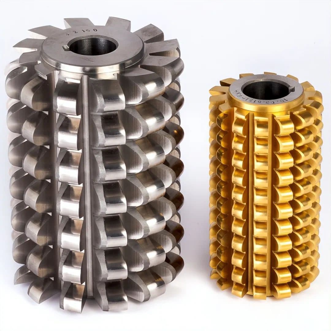
Hobs for manufacturing automotive and industrial roller chain sprockets are produced to meet a diverse array of standardized and custom specifications. These precision cutting tools are crucial for ensuring the accurate and efficient production of sprockets, which are integral components in power transmission systems.
General sprocket pitch range: 6.35 mm to 76.2 mm (1/4 inch to 3 inches).
Standards: Sprocket hobs are manufactured in compliance with various international and regional standards, including:
It’s important to note that while there are numerous standards, reputable manufacturers adhere to recognized industry norms. When selecting a sprocket hob, it’s crucial to verify the authenticity and compliance of the tool with the appropriate standards for your specific application.
Custom hobs can also be designed and manufactured to meet unique sprocket specifications that fall outside standard parameters, allowing for greater flexibility in specialized industrial applications.
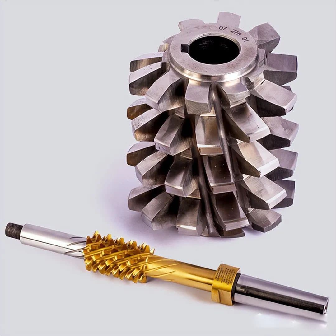
The worm gear hob is a specialized cutting tool essential for the precision manufacturing of worm gears. The most critical types of worm hobs correspond to the various worm gear profiles: ZI (involute), ZN (straight-sided), ZK (convolute), and ZA (extended addendum). Each type is designed to produce a specific worm gear tooth profile, ensuring optimal meshing and performance characteristics.
Hobs can be manufactured with either a single or multiple thread (head) configuration. The choice between single and multiple threads affects the cutting speed and efficiency of the hobbing process. Hobs are also available in two mounting styles: with a central bore (hole type) for arbor mounting or with an integral shank (handle type) for direct machine attachment. The lead angle of worm hobs typically ranges from 1 to 45 degrees, with the specific angle selected based on the worm gear design requirements and hobbing machine capabilities.
Two primary methods are employed for cutting with a worm gear hob:
The choice between these cutting methods depends on factors such as gear size, required accuracy, production volume, and available machinery. Both methods can produce high-quality worm gears when properly implemented with the appropriate hob design and cutting parameters.
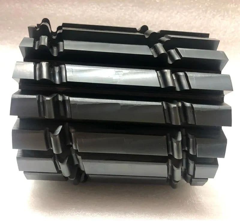
Hobs with specialized tooth profiles can be employed for a wide range of components, extending beyond standard involute gears. These specialized cutting tools are designed to generate and process external gears with unique tooth geometries, accommodating specific functional requirements or manufacturing constraints.
Applications for special profile hobs include:
When designing and implementing special profile hobs, several factors must be considered:
By leveraging specialized hob designs, manufacturers can achieve complex external gear geometries efficiently, often eliminating the need for additional machining operations and improving overall part quality and performance.
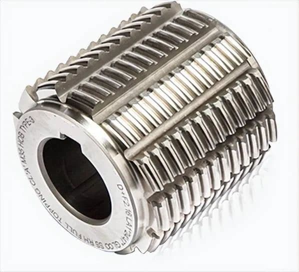
The manufacturing of synchronous pulley hobs is a critical process in the production of precision power transmission components. These specialized cutting tools are designed to generate a wide range of belt and pulley profiles, including both involute and High Torque Drive (HTD) geometries, ensuring optimal power transfer and synchronization in various mechanical systems.
Two primary design configurations are available: top-cut and non-top-cut. The top-cut design features a modified tooth profile that allows for improved chip evacuation and reduced cutting forces, while the non-top-cut variant offers enhanced tool life and is often preferred for larger production runs.
Common pulley profiles machined by these hobs include:
The selection of the appropriate hob and profile depends on factors such as power requirements, speed, precision needs, and environmental conditions of the intended application. Advanced manufacturing techniques, including precision grinding and coating processes, are employed to ensure the hobs maintain tight tolerances and exhibit excellent wear resistance, contributing to the production of high-quality synchronous pulleys across various industries.
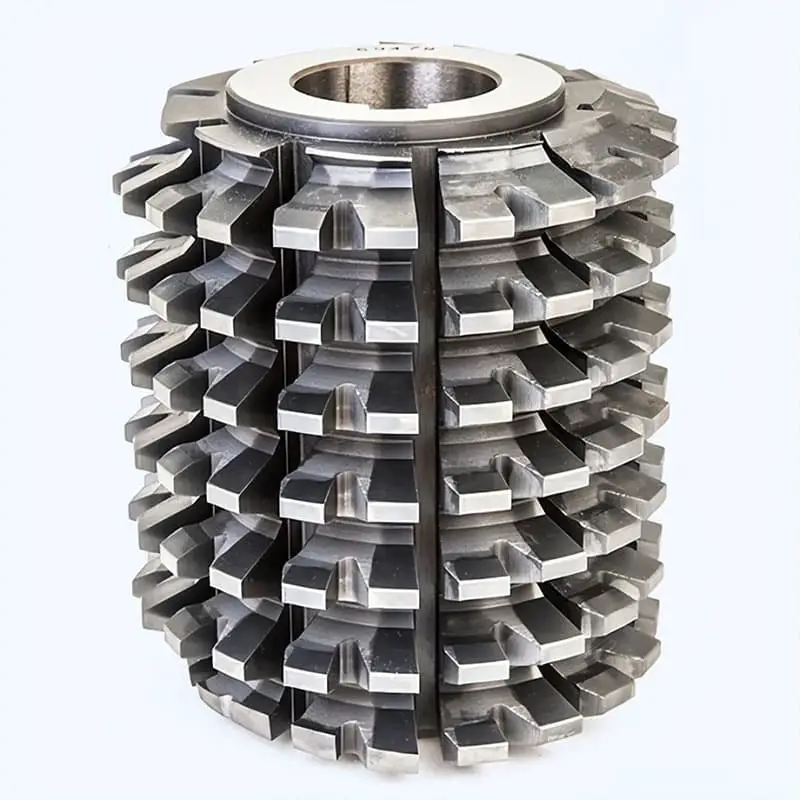
The implementation of specially engineered double-cut hobs revolutionizes gear manufacturing efficiency by integrating advanced cutting edges within strategically designed grooves. These high-performance tools are optimized for gears with modules 5.5 and above, addressing the unique challenges of heavy-duty gear production.
Benefits:
Utilizing these state-of-the-art double-cut hobs offers multiple advantages in gear manufacturing:
The effectiveness of these double-cut hobs is particularly pronounced in medium to large-scale gear production, where the time and cost savings can significantly impact overall manufacturing efficiency and productivity.
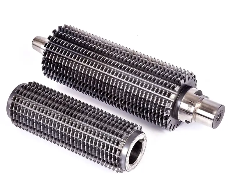
The CNC gear hobbing machine utilizes this specialized hob for high-speed dry cutting, significantly enhancing productivity in gear manufacturing processes.
This hob’s design features an extended cutting edge length and a high number of flutes, optimizing chip evacuation and heat dissipation. These characteristics substantially increase the hob’s tool life between regrinds, reducing downtime and maintenance costs.
Ideal for integration into large-scale automated production lines, this hob excels in continuous operation environments. To maximize performance, it’s crucial to adhere to the hob’s specific parameters, including diameter, number of flutes, number of starts, and recommended cutting data such as cutting speed, feed rate, and depth of cut.
The primary objectives when implementing this hob are to minimize cycle times and maximize tool life, leading to improved overall equipment effectiveness (OEE).
Benefits:
Applications:
For optimal results, it’s recommended to work closely with the hob manufacturer to select the appropriate coating, substrate material, and geometry tailored to specific gear materials and production requirements.

