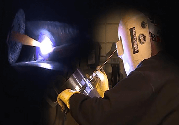
Imagine you’re in a workshop, surrounded by the sizzle and spark of welding torches. Have you ever wondered what makes one welding method different from another? This article takes you on a journey through ten essential welding techniques, from electrode arc welding to friction welding. You’ll discover how each method works, its unique applications, and the advantages it offers. Whether you’re a seasoned welder or a curious novice, this guide provides valuable insights to enhance your understanding of welding processes. Dive in and expand your welding knowledge!
Arc is a persistent and intense gas discharge phenomenon that occurs between two charged conductors.
Arc Formation
(1) Short Circuit between Welding Rod and Workpiece
In the event of a short circuit, individual contact points with high current density are heated by resistance heat, q = I^2Rt, where I is the current and R is the resistance. The electric field intensity in the small air gap is very high, which results in:
① A small number of electrons escaping
② The individual contact points being heated, melted, and even evaporated and vaporized
③ The presence of many metal vapors with low ionization potential.
Related reading: How to Choose the Right Welding Rod?
(2) Lifting the Welding Rod at an Appropriate Distance
Under the influence of thermal excitation and a strong electric field, the negative electrode emits electrons and moves at high speed, colliding with neutral molecules and atoms, exciting or ionizing them. This results in:
Arc Structure and Temperature Distribution
The arc consists of three parts: the cathode area (usually a bright white spot on the end of the electrode), the anode area (a thin bright area in the bath corresponding to the electrode’s end on the workpiece), and the arc column area (the air gap between the two electrodes).
Conditions for Stable Arc Combustion
(1) Appropriate Power Supply
There must be a power supply that meets the electrical requirements of the welding arc.
a) If the current is too low, the gas ionization between the air gaps is insufficient, the arc resistance is high, and a higher arc voltage is required to maintain the necessary ionization level.
b) As the current increases, the gas ionization level increases, the conductivity improves, the arc resistance decreases, and the arc voltage decreases. However, the voltage must not decrease beyond a certain point, in order to maintain the necessary electric field strength and ensure the emission of electrons and the kinetic energy of charged particles.
(2) Proper Electrode Selection and Cleaning
It is important to use clean electrodes with the appropriate coating.
(3) Prevention of Partial Blowing
Measures must be taken to prevent partial blowing.
(4) Electrode Polarity
In welding, when using a DC welding machine, there are two methods: positive connection and reverse connection.
AC arc welding equipment is widely used, and the electrode polarity changes frequently, so there is no issue with polarity.
The workpiece is connected to the positive pole of the power supply and the electrode is connected to the negative pole. This is the normal connection method used for general welding operations.
The workpiece is connected to the negative pole of the power supply and the electrode is connected to the positive pole. This method is generally used for welding thin plates to prevent burn-through.
1). Welding process
2). Welding rod arc welding heating characteristics
Composition of Welding Rod for Manual Arc Welding
The welding rod for manual arc welding is composed of a welding core and a coating.
① As the electrode for arc welding, it conducts electricity with the workpiece to form an arc.
② During the welding process, it continuously melts and is transferred to the moving molten pool, where it crystallizes with the molten base metal to form a weld.
① Role of Coating
The coating provides effective protection for the molten pool and slag joint, deoxidizes and desulfurizes the molten metal in the pool, and infiltrates alloy into the molten pool metal to improve the mechanical properties of the weld. It also stabilizes the arc to improve the welding process.
② Composition of Coating
Types of Welding Rod
Welding rods are divided into ten categories:
Selection Principle of Welding Rod
When selecting a welding rod, the following principles should be considered:
Change and Distribution of Temperature in Weldment
The temperature of the metal in the weld zone starts to increase and reaches a steady state, and then gradually decreases to room temperature.
Changes in Microstructure and Properties of Welded Joints (Using Low-Carbon Steel as an Example)
Main Defects of Welded Joints
Blowholes are holes formed when bubbles in the molten pool do not escape during solidification.
Prevention Measures:
a) Dry the welding rod and thoroughly clean the welding surface and surrounding area of the workpiece.
b) Use an appropriate welding current and operate correctly.
Slag inclusion is slag that remains in the weld after welding.
Precautions:
a) Carefully clean the welding surface.
b) Thoroughly remove slag between layers during multi-layer welding.
c) Slow down the rate of crystallization of the molten pool.
a) Hot Crack
Hot crack is a crack in the welded joint that forms when the metal cools near the solidus during welding.
Preventive Measures:
Reduce structural stiffness, preheat before welding, reduce alloying, choose low hydrogen electrodes with good crack resistance, etc.
b) Cold Crack
Cold crack is a crack in the welded joint that occurs when it cools to a lower temperature.
Precautions:
a) Use a low hydrogen electrode, dry and remove oil and rust from the workpiece surface.
b) Preheat before welding and heat treat after welding.
Incomplete penetration is a phenomenon where the root of the welded joint is not fully penetrated.
Causes:
Too small a groove angle or gap, too thick a blunt edge, unclean groove, too thick electrode, too fast welding speed, too small welding current, and improper operation.
Incomplete fusion is a phenomenon where the fusion between the weld and base metal is not complete.
Causes:
Unclean groove, excessive electrode diameter, and improper operation.
Undercut is a groove or depression along the base metal part of the weld toe.
Causes:
Excessive welding current, too long arc, improper electrode angle, etc.
Causes of Welding Stress and Deformation
Local heating during welding is the main cause of welding stress and deformation.
Basic Forms of Welding Deformation
Process Measures to Prevent and Reduce Welding Deformation
Process Measures to Reduce Welding Stress
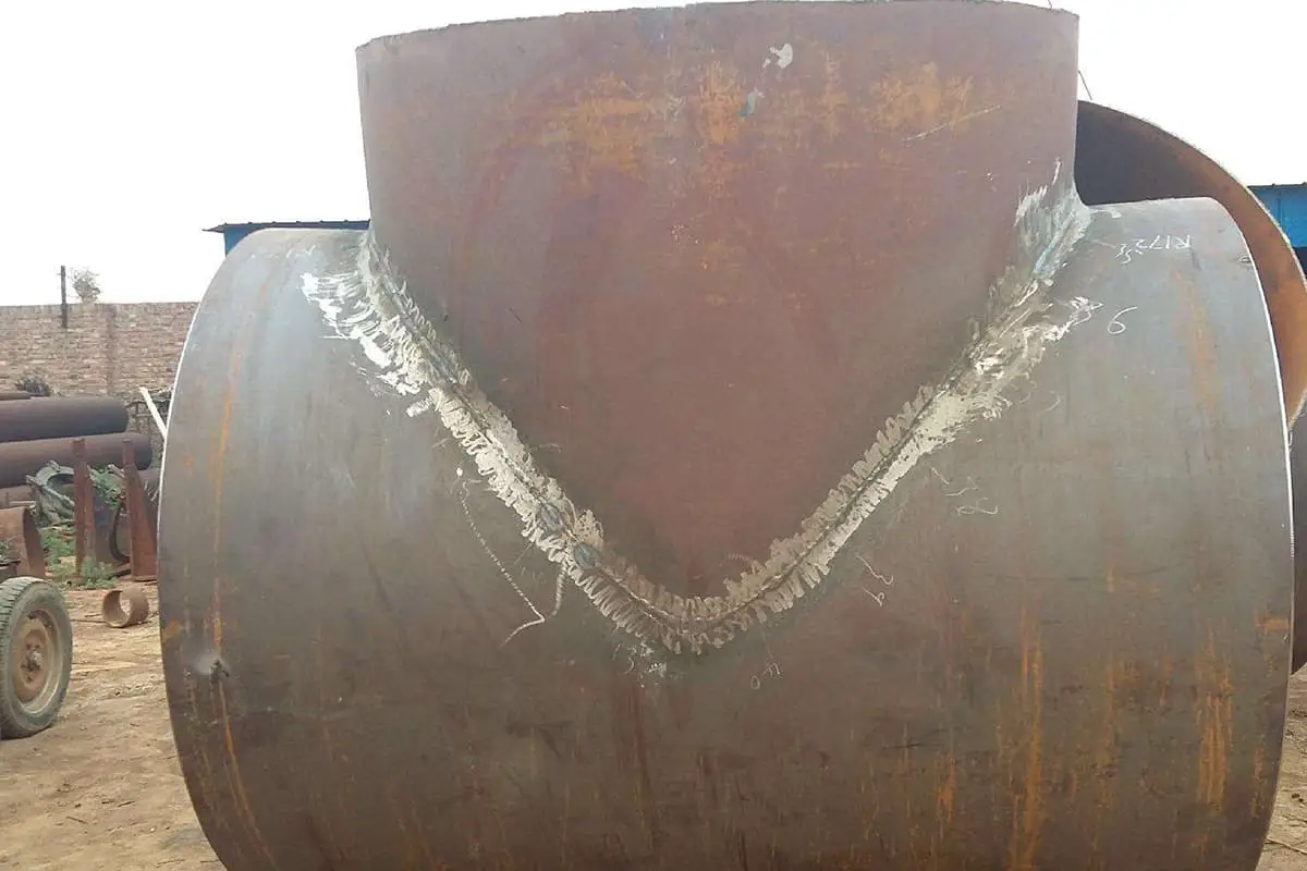
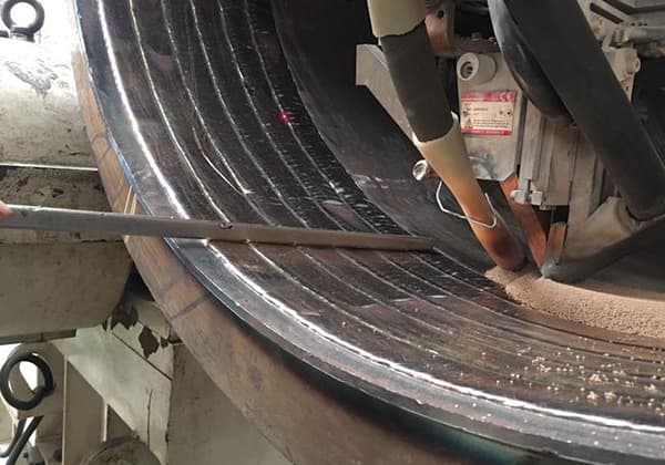
The process of welding where the arc burns beneath a layer of flux is known as Submerged Arc Welding (SAW).
SAW is characterized by automatic assembly for arc striking and electrode feeding, thus it is also referred to as Submerged Arc Automatic Welding (SAAW).
Submerged Arc Welding (SAW) offers several benefits, including:
However, SAW is not suitable for all types of welding. It is best suited for welding flat, long straight seams, and large diameter circumferential welds. For short welds, zigzag welds, narrow positions, and thin plate welding, SAW may not provide the desired results.
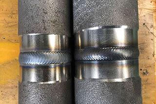
Gas Shielded Welding that utilizes argon as a shielding gas is known as Tungsten Inert Gas (TIG) Welding or Argon Arc Welding.
Argon, being an inert gas, protects the electrode and the molten metal from the damaging effects of air.
Based on the type of electrode used, Argon Arc Welding can be further categorized into two types:
Non melting electrode argon arc welding
Non-molten Electrode Argon Arc Welding is a type of Argon Arc Welding where the electrode is only used to generate an electric arc and emit electrons. The filler metal is added separately.
Common electrodes used in this process are Tungsten electrodes that are doped with thorium oxide or cerium oxide. These electrodes have high electron thermal emission ability, a high melting point, and a high boiling point (3700K and 5800K, respectively).
MIG welding
Tungsten Inert Gas (TIG) Welding is known for its low current and shallow penetration. Despite this, it is often used for welding medium to high thickness alloys such as titanium, aluminum, copper, and others. This is due to its ability to achieve high productivity levels.
The following are the key characteristics of Argon Arc Welding (TIG Welding):
Gas Shielded Welding that uses carbon dioxide (CO2) as a shielding gas is referred to as Gas Metal Arc Welding (GMAW) or Metal Inert Gas (MIG) Welding.
The primary purpose of using CO2 as a shielding gas is to isolate the welding area from air and prevent the harmful effects of nitrogen on the molten metal. This helps to maintain the integrity of the weld and produce high-quality results.
During welding:
2CO2=2CO+O2 CO2=C+O2
Therefore, welding is carried out in CO2, CO and O2 oxidation atmosphere.
Characteristics of carbon dioxide gas shielded welding:
Electroslag Welding (ESW) is a welding technique that utilizes the heat generated by the resistance of an electric current passing through a liquid slag to produce a weld.
Typically, a welding arc is a free arc, meaning only a portion of the gas in the arc area is ionized and the temperature is not high enough.
However, when the free arc is compressed into an arc with high energy density, the gas in the arc column becomes fully ionized and transforms into plasma, a fourth state of matter that consists of positive and negative ions.
Plasma arcs have high temperatures (ranging from 15,000 to 30,000K), high energy densities (up to 480 kW/cm2), and fast-moving plasma flows (several times the speed of sound).
There are three compression effects in Plasma Arc Welding:
These three compression effects result in a plasma arc with a diameter of only about 3mm, but with greatly improved energy density, temperature, and air velocity.
The following are the key characteristics of Plasma Arc Welding:
Vacuum Electron Beam Welding (VEBW) is a process of welding where a directional and high-speed electron beam is directed towards the workpiece, converting its kinetic energy into heat energy and melting the workpiece to form a weld.
The following are the key characteristics of Vacuum Electron Beam Welding (VEBW):
Laser Welding is a welding process that uses a focused laser beam to deliver heat to the weldment.
The following are the key characteristics of Laser Welding:
Resistance welding is a welding process where pressure is applied through electrodes after the workpieces are combined. The resistance heat generated by the current passing through the contact surface of the joint and the surrounding area is used to weld the workpieces.
There are various types of resistance welding, including spot welding, seam welding, and butt welding. Each of these methods have unique characteristics and are used for specific welding applications.
Spot welding is a resistance welding technique where the workpieces are joined together in a lap joint and placed between two electrodes. The resistance heat generated from the current passing through the contact surface of the joint and surrounding area melts the base metal to form a welding spot.
This method is primarily used for welding sheets and involves three steps: preloading to ensure good contact of the workpieces, turning on the power to form a nugget and plastic ring at the weld, and breaking the point of forging which allows the nugget to cool and crystallize under the continuous action of pressure, resulting in a soldered joint with a dense structure and no shrinkage cavity or crack.
Seam welding is a type of resistance welding where the workpiece is arranged in a lap or butt joint and positioned between two roller electrodes. The rollers apply pressure to the workpiece as they rotate, and power is continuously or intermittently applied to form a continuous weld. This method of welding is commonly used for structures that require regular welds and have sealing requirements, with plate thicknesses typically less than 3mm.
Butt welding is a process in resistance welding that joins two workpieces along their entire contact surface.
Resistance butt welding
Resistance butt welding is a process in which two workpieces are joined together end-to-end in a butt joint and are then heated to a plastic state by resistance heat. Pressure is then applied to complete the welding process. This method is typically used for welding workpieces with simple shapes, small diameters or lengths less than 20mm, and low strength requirements.
Flash butt welding
Flash butt welding is a process where two workpieces are assembled into a butt joint and connected to a power supply. The end faces of the workpieces are gradually brought into contact and heated with resistance heat until they reach a preset temperature within a certain depth range. This results in the generation of a flash, which melts the end metal. Power is then cut off and an upsetting force is quickly applied to complete the welding.
The joint quality of flash butt welding is superior to that of resistance welding and the mechanical properties of the weld are equal to those of the base metal. There is no need to clean the pre-welded surface of the joint before welding.
Flash butt welding is commonly used for welding important workpieces and can be used to weld both similar and dissimilar metals, as well as metal wires with a thickness as small as 0.01mm and metal bars and profiles with a thickness as large as 20000mm.
Friction welding is a pressure welding process that uses heat generated from the friction between the surfaces of the workpieces to bring the end face to a thermoplastic state, then quickly upsetting to complete the welding.
Key Characteristics of Friction Welding:
Cleared Surfaces: The friction generated during the welding process clears the oxide film and impurities on the contact surface of the workpieces, resulting in a dense and defect-free structure in the welded joint.
Compatibility with Different Metals: Friction welding can be used to weld both the same and different metals, making it well-suited for a wide range of welding applications.
High Productivity: Friction welding is known for its high productivity, making it an efficient method for welding workpieces.
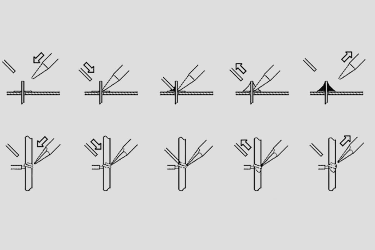
Brazing can be classified into two categories based on the melting point of the brazing filler metal: hard brazing and soft brazing.
Brazing
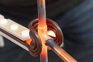
Brazing with a solder melting point higher than 450°C is known as hard brazing. The filler metals used for hard brazing include copper-based, silver-based, aluminum-based, and other alloys. Commonly used fluxes include borax, boric acid, fluoride, chloride, among others. The heating methods for hard brazing include flame heating, salt bath heating, resistance heating, and high-frequency induction heating. The strength of the brazed joint can reach 490MPa, making it suitable for workpieces that experience high stress and are exposed to high working temperatures.
Soldering
Brazing with a solder melting point below 450℃ is known as soft brazing. Tin-lead alloys are commonly used as soft solders. Rosin and ammonium chloride solutions are commonly used as fluxes, and the soldering iron and other flame heating methods are commonly used for heating.
The following are the key characteristics of brazing:

