Revolutionizing Underwater Welding: Advancements and Applications
Imagine working deep underwater, where visibility is low and pressure is high, yet the task at hand requires precision: welding. This article explores the fascinating world of underwater welding, a critical technology for maintaining marine structures. You’ll learn about various welding methods, their challenges, and groundbreaking applications in industries like oil and gas. Whether it’s repairing pipelines or constructing offshore platforms, understanding these advanced techniques can open up a world of innovation in marine engineering. Dive in to discover how engineers overcome the ocean’s hurdles to keep our underwater infrastructure intact.
Due to the harsh working environment in the ocean, marine engineering structures are exposed to various challenges, including structural loads, storm, waves, tidal forces, corrosion from seawater, erosion from sand flows, and the threat of fire and explosion from petroleum and natural gas.
Moreover, the major parts of marine engineering structures are submerged underwater, making it difficult and costly to inspect and repair welded joints after they are in service. Any significant structural damage or overturning accidents can result in severe loss of life and property.
Therefore, strict quality requirements are imposed on the design, manufacturing, material selection, and welding construction of marine engineering structures. With the development of the marine, oil, and natural gas industries, offshore pipeline projects are increasingly venturing into deeper waters.
Therefore, conducting research and enhancing the application of underwater welding technology is of great significance in the development of the marine industry, offshore oil field exploitation, and utilizing the abundant marine resources for the benefit of humanity.
Currently, underwater welding technology has been widely applied in marine engineering structures, subsea pipelines, ships, shipyards and port facilities, river engineering, and nuclear power plant maintenance.
Underwater welding has become a key technology for the assembly and maintenance of large-scale marine structures such as oil drilling platforms and oil pipelines.
2. Classification and Characteristics of Underwater Welding Methods
2.1 Classification of Underwater Welding Methods
Currently, there are various types of underwater welding methods being applied and researched worldwide. It can be said that almost all welding technologies used in land-based production have been experimented with underwater.
However, the most mature and widely used methods are several arc welding techniques.
Underwater welding can generally be classified into three categories based on the welding environment: wet underwater welding, dry underwater welding, and local dry underwater welding.
However, with the development of underwater welding technology, new methods have emerged, such as underwater stud welding, underwater explosive welding, underwater electron beam welding, and underwater exothermic welding.
2.2 Characteristics of Underwater Welding
Underwater welding processes are much more complex than land-based welding processes due to the underwater environment. In addition to welding techniques, factors such as diving operations also come into play.
The characteristics of underwater welding are as follows:
(1) Poor visibility:
Water absorbs, reflects, and refracts light much more strongly than air, resulting in rapid light degradation when propagating through water. Additionally, during welding, a large number of bubbles and smoke are generated around the arc, significantly reducing the visibility of the underwater arc.
In areas with muddy seabeds or sediment-laden waters, visibility underwater becomes even worse. As a result, underwater welding has traditionally been considered blind welding, severely affecting the performance of diver welders and contributing to the high occurrence of defects and low quality of welded joints.
(2) High hydrogen content in welds:
Hydrogen is a major concern in welding, as exceeding the allowed hydrogen content can easily lead to cracking and structural damage. Underwater arcs cause thermal decomposition of water surrounding them, increasing the dissolved hydrogen in the weld.
Generally, the diffusible hydrogen content in underwater welding is 27-36 mL/100g, several times higher than that in land-based acidic electrode welding. The poor quality of weld joints in underwater shielded metal arc welding is closely related to the high hydrogen content.
(3) Rapid cooling rate:
During underwater welding, seawater has a higher thermal conductivity compared to air, being approximately 20 times higher. Even freshwater has a thermal conductivity several times higher than that of air.
When wet or local dry underwater welding is employed, the workpiece is directly in contact with water, resulting in a significant rapid cooling effect on the weld, which can lead to the formation of high hardness quenched structures.
Therefore, only dry underwater welding can avoid the cold effect.
(4) Pressure effects:
With increasing pressure (0.1 MPa increase for every 10 meters of water depth), the arc column becomes thinner, the weld width narrows, and the weld height increases.
Additionally, the increased density of the conducting medium makes ionization more difficult, leading to higher arc voltage, reduced arc stability, and increased spatter and smoke.
(5) Difficulty in achieving continuous operations:
Due to the influence and limitations of the underwater environment, continuous welding is often challenging. In many cases, welding has to be performed intermittently, resulting in discontinuous welds.
3. Applications, Metallurgical Characteristics, and Design of Underwater Welding Electrodes for Wet Underwater Welding
3.1 Applications of Wet Underwater Welding in Marine Engineering
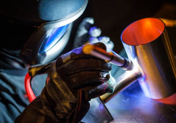
Wet underwater welding is performed by divers in a water environment, as shown in Figure 2. Due to poor visibility underwater, diver welders cannot see the welding process clearly, leading to the occurrence of blind welding. It is difficult to ensure the quality of underwater welding, especially the water tightness.
Therefore, achieving high-quality weld joints with this method is challenging, particularly for welding structures used in critical applications.
However, due to its simplicity, low cost, flexibility, and adaptability, wet underwater welding using coated electrodes and manual arc welding still continues to be researched in various countries. Further applications of these methods are expected in the future.
Figure 1: Schematic diagram of wet underwater welding
Wet underwater welding has been widely applied in the United States, with the American Welding Society’s AWS standard (AWS D3.6) being the most influential document guiding the design of wet underwater welding.
The most commonly used methods in wet underwater welding are shielded metal arc welding (SMAW) and flux-cored arc welding (FCAW). During welding, diver welders use waterproof-coated electrodes and welding tongs specifically designed or modified for underwater welding.
Although significant progress has been made in wet underwater welding, it can be said that achieving high-quality weld joints in water depths exceeding 100 meters is still challenging, and therefore, it cannot yet be used for welding critical marine engineering structures.
However, with the development of wet underwater welding technology, many issues associated with wet underwater welding are being overcome to some extent.
The use of well-designed electrode coatings and waterproof coatings, along with strict welding process management and certification, has led to successful applications of wet underwater welding in the repair of non-essential structural components in the North Sea in 1991. Wet underwater welding has now been successfully applied in the repair of auxiliary components on North Sea platforms.
Additionally, wet underwater welding technology is widely used in shallow water areas with favorable marine conditions and for welding components that do not require high stress resistance.
Currently, the Gulf of Mexico is the most widely used region for wet underwater welding and wet underwater welding electrodes. Wet underwater welding technology has been used for the repair of the bubbler tubes in Gulf of Mexico nuclear reactors and for underwater welding repairs at a depth of 78 meters on Amoco Trinidad’s oil platform.
The research on this technology is of great practical significance for the future repair of underwater pipelines in the Bohai Bay and Liaodong Bay in China, as well as for the repair of non-critical components such as sacrificial anode replacement.
Table 1: Gas Composition of Shielded Metal Arc Welding Flux (Volume Percentage)
Electrode Types
H2
CO
CO2
Other
J422(E4303)
45~50
40~45
5~10
<5
J507(E5015)
20~30
50~55
20~25
<5
As the water depth increases in underwater welding, the volume of the arc bubbles gradually decreases due to compression.
However, insufficient arc bubbles can lead to an increased tendency for weld metal porosity. When the arc bubbles become too few, the arc is easily extinguished, making the welding process difficult to proceed smoothly. The growth of arc bubbles should satisfy the following physical conditions:
pg ≥ pa + ph + ps
In the equation:
pg represents the pressure inside the bubble,
pa represents atmospheric pressure,
ph represents the hydrostatic pressure around the bubble,
ps represents the additional pressure caused by surface tension of the bubble.
During land-based welding, ph is close to zero. However, in underwater welding, ph increases with water depth, while pa and ps can be considered unaffected by water depth.
Therefore, to ensure smooth welding, it is necessary to increase pg. One way to increase pg is to increase the arc temperature, which can be achieved by adjusting the welding current. This is because a higher arc temperature can dissociate sufficient hydrogen and oxygen. Another way is to enhance the gas-producing function of the electrode coating, so that more CO2 and CO gases are generated during the combustion of the electrode coating.
However, a high proportion of hydrogen in the arc bubbles can lead to the generation of two types of hydrogen-related defects: an increased tendency for weld porosity and an increased susceptibility to hydrogen-induced cracking in the weld metal and heat-affected zone.
Therefore, in formulating the electrode coating, it is necessary to ensure sufficient pressure in the arc bubbles while also attempting to reduce the proportion of hydrogen in the arc bubbles. Adding an appropriate amount of CaF2 and SiO2 to the coating can achieve this purpose, as these additives help to reduce the hydrogen content.
The chemical and metallurgical reactions involving the products CaO, SiF or SiF4, MnO, SiO2, and TiO2 as a flux in the molten pool during underwater welding are important. These reactions result in the formation of gases like HF, which do not have any harmful effects on the weld metal and also contribute to increasing the pressure in the arc bubbles. The floating slag contains CaO, SiF or SiF4, MnO, SiO2, and TiO2, which help remove impurities from the molten pool. HF gas also aids in increasing the pressure in the arc bubbles.
Underwater welding has a higher susceptibility to hydrogen-induced cracking compared to land-based welding. This is due to the strong cooling effect of water on the workpiece, causing phase transformation and the formation of martensite in the heat-affected zone of low carbon steels. When the carbon equivalent in steel exceeds 0.4%, the hardness in the heat-affected zone can exceed 400 HV.
Additionally, if the hydrogen content is high during welding and the weld absorbs a significant amount of hydrogen, it can lead to the formation of hydrogen-induced cracks under the influence of welding thermal stress and phase transformation stress. Therefore, it is essential to reduce the proportion of hydrogen in the arc bubbles to mitigate the risk of hydrogen-induced cracking.
3.3 Design of Electrode Coating Formulation
(1) Selection of Slag System
Slag is the protective layer formed on the surface of the weld joint during the welding process, consisting of the fusion of the welding core, electrode coating, and the base material through high-temperature metallurgical reactions.
The properties of the slag, such as its oxidation-reduction ability, flowability, and permeability, directly affect the protection of the weld metal and the formation of the weld joint.
In this experiment, a slag system consisting of SiO2 – TiO2 – CaF2- CaO was chosen, which falls between the acidic and alkaline slag systems. This choice ensures good welding process performance and effectively reduces the harmful effects of hydrogen in the arc bubbles. The corresponding minerals and chemical products were selected to meet the composition requirements of the slag system.
(2) Optimization of Coating Formulation
Table 2 presents the results of 10 formulations that were tested based on the metallurgical characteristics of wet underwater welding.
The content of each substance in the formulations is as follows:
TiO2 in hematite: 52%;
CaF2 in fluorite: 98%;
CaCO3 in marble: 98%;
Mn in low-carbon ferromanganese: 85%;
Ti in ferrotitanium: 75%;
Si in ferrosilicon: 45%; and SiO2 in feldspar: 93%.
The optimization process involved conducting performance tests while formulating the new formulations. All welding tests were conducted in a pressurized vessel simulating water depths of 70-100 meters.
Apologies for the confusion. Here is the corrected information:
Table 2: Composition and Test Results of Different Formulations
NO.
Hematite
Fluorite
Marble
Low carbon manganese iron
Ferrotitanium
Ferrosilicon
Cellulose
Feldspar
Iron powder
Arc bubble characteristics
1
20
10
20
10
5
5
–
12
18
Reduced arc extinguishing with fewer bubbles
2
20
10
25
10
6
6
–
10
13
Reduced arc extinguishing with fewer bubbles
3
20
15
20
10
7
7
–
13
Reduced arc extinguishing with fewer bubbles
4
15
12
25
10
6
6
3
10
10
Stable bubbles
5
15
12
25
10
6
6
5
13
8
Stable bubbles
6
15
12
25
10
6
6
7
15
4
Stable bubbles
7
10
18
25
10
6
6
5
10
10
Stable bubbles
8
10
16
30
10
6
6
3
12
7
Stable bubbles
9
10
15
30
10
5
5
5
15
5
Stable bubbles
10
10
15
35
5
5
5
5
15
5
Stable bubbles
3.3 Process Performance and Mechanical Performance Testing
A small quantity of welding rods with a diameter of 4.0 mm was produced using formulations 1-10 on a 25-ton hydraulic coating machine. The following tests were conducted:
(1) Porosity and Formability Test
For the test, Q235-C 6 mm sheet metal was used. When welding was performed underwater at a depth of 70 m using formulations 1-3, the lack of sufficient gas-forming materials made it difficult to stabilize the presence of arc bubbles, resulting in severe porosity. The welding process could not proceed smoothly.
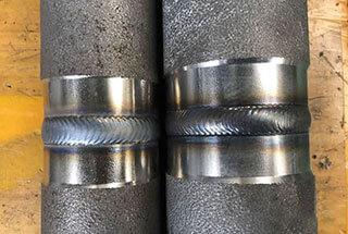
Formulations 4-10, which included increased gas-forming materials and reduced hydrogen content, showed no porosity. Among them, formulations 7-9 exhibited good formability. The morphological characteristics are shown in Figure 2.
(2) Determination of Diffusible Hydrogen Content in Weld Metal
The diffusible hydrogen content is a key indicator of welding rod performance. In this study, the glycerol method specified in GB 3965-93 was used to determine the diffusible hydrogen content of formulations 4-10, which showed satisfactory initial performance.
The measured results for formulations 4-10 were as follows (mL/100g): 15.5, 16, 18.2, 7.2, 6.7, 6.9, 7.2. It can be seen that formulations 7-10 meet the requirements of GB 5117-95 (diffusible hydrogen ≤ 8 mL/100g).
Figure 2: Appearance of Weld Seam Formed by Formulations 4-10
(3) Mechanical performance test
Based on the comprehensive results of the process performance tests, it can be analyzed that the welding rods formulated with 7, 8, and 9 meet the requirements for underwater welding. Although formulation 10 meets the requirement for diffusible hydrogen content, the weld seam formed using this formulation has poor formability and is therefore not adopted.
Welded test plates were prepared using the welding rods formulated with 7, 8, and 9 (on 16Mn plates with a thickness of 19 mm) for tensile testing of the weld metal and V-notch impact testing. The test results are shown in Table 3.
Table 3: Mechanical Performance of Weld Metal
NO.
Tensile Strength (MPa)
Elongation Rate (%)
Section Contraction Rate (%)
Impact Absorption Energy (Akv/J)
7
525
23
38
85
8
496
24
41
125
9
516
24.5
43
130
According to Table 3, it can be seen that the mechanical performance indicators of welding rods No. 7-9 fully meet the requirements of GB 5117-95 for low carbon steel and low alloy high-strength steel, making them suitable for underwater welding of low carbon steel and low alloy steel.
4. Application of Dry Underwater Welding Technology
Dry underwater welding is a method in which the welding area is completely or partially dried by using gas to remove the surrounding water, allowing the underwater welder to work under dry or semi-dry conditions. When performing dry underwater welding, complex pressure chambers or workstations need to be designed and manufactured.
Depending on the pressure inside the pressure chamber or workstation, dry underwater welding can be further divided into high-pressure dry underwater welding and atmospheric pressure dry underwater welding.
4.1 Application of High-Pressure Dry Underwater Welding Technology
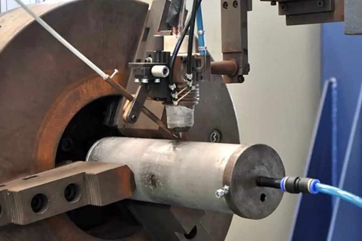
High-pressure dry underwater welding is shown in Figure 2. With the increase in underwater welding projects, the depth of underwater engineering, and the higher requirements for welding quality, high-pressure dry underwater welding is gaining more attention due to its advantages of high welding quality and good joint performance.
Wet underwater welding and localized dry underwater welding are generally only used for repairing non-critical structures at depths of several meters to tens of meters, with practical application depths usually not exceeding 40m.
In order to adapt to the development of offshore engineering towards deeper waters, many countries have increased research and application of high-pressure dry underwater welding technology.
Figure 3: Schematic Diagram of High-Pressure Dry Underwater Welding
Currently, for underwater maintenance operations, high-pressure track TIG welding systems are widely used. Well-known systems include the PRS system and the OTTO system. The PRS system was developed by Statoil, a Norwegian company, with the goal of performing welding at a water depth of 1000m. Successful pipeline welding has been carried out at a water depth of 334m, achieving a -30℃ impact energy of 300J and a microhardness of the weld seam below 245HV.
To date, this system has successfully completed more than 20 underwater pipeline repair tasks. The OTTO system in the UK consists mainly of a welding chamber and a track TIG welding machine. Experimental results have shown that the weld seam at a water depth of 135m achieves a -10℃ impact energy of 180J and a fracture strength of 550MPa. This system has worked continuously underwater for 4 weeks, completing a total of 18 weld seams, and the welding procedures and quality have been certified by the Norwegian Lloyd’s Register.
In China, in October 2002, underwater dry high-pressure welding technology was planned as a significant part of the “Key Technologies for Exploration and Development of Bohai Oilfield” under the National 863 Program. This project is led by the Beijing Institute of Petrochemical Technology.
Currently, the first high-pressure welding laboratory in China has been designed and established, equipped with a high-pressure welding test chamber for conducting welding tests and research at different pressure levels. Subsequently, annual plans for high-pressure welding process experiments and process evaluations have been implemented.
High-pressure dry welding was first proposed by the United States in 1954 and was used for production starting in 1966. It can weld subsea pipelines with diameters of 508mm, 813mm, and 914mm.
Currently, the maximum practical water depth is around 300m. In this welding method, the bottom of the gas chamber is open, and gas pressure slightly higher than the water pressure at the working depth is introduced to discharge the water from the bottom opening of the chamber, allowing welding to be performed in a dry gas chamber.
Generally, welding methods such as electrode arc welding or inert gas shielded arc welding are used. It is one of the best welding methods in terms of quality in underwater welding and can achieve a level close to that of onshore welds. However, there are three issues that need to be addressed:
(1) Due to the limitations imposed by the engineering structure shape, size, and position, the gas chamber has significant limitations and is less adaptable.
Currently, it is only suitable for welding structures with simple and regular shapes, such as subsea pipelines.
(2) A set of life support, humidity control, monitoring, lighting, safety assurance, communication, and other systems must be provided.
The auxiliary work time is long, requiring a large surface support team, resulting in higher construction costs. For example, the welding device (MOD-1) from TDS company in the United States, which can weld pipelines with a diameter of 813mm, is valued at up to $2 million.
(3) The issue of “pressure influence” also exists.
When welding at great depths (from tens to hundreds of meters), the characteristics of the welding arc, metallurgy, and welding process are all affected to varying degrees as the gas pressure around the arc increases. Therefore, it is necessary to carefully study the influence of gas pressure on the welding process in order to obtain high-quality welds.
4.2 Application of Atmospheric Pressure Dry Underwater Welding Technology
Welding is performed within a sealed pressure chamber, where the pressure inside the chamber is equal to atmospheric pressure on land and independent of the water pressure in the surrounding environment, as shown in Figure 4.
In fact, this welding method is not affected by water depth or the presence of water, and the welding process and quality are similar to welding on land.
However, the application of atmospheric pressure welding systems in offshore engineering is limited. The main reason for this is the difficulty in ensuring the sealing of the welding chamber on structures or pipelines and maintaining the desired pressure inside the chamber.
An operational system of this kind, jointly developed by Petrobras and Lockheed, was applied in the Amazon Basin. The equipment for atmospheric pressure dry welding is even more expensive than that for high-pressure dry underwater welding, and it requires a larger number of welding support personnel.
Therefore, it is generally only used for deep-water welding of critical structures. The biggest advantage of this method is its ability to effectively eliminate the influence of water on the welding process. The welding conditions are identical to those on land, ensuring the highest welding quality.
Figure 4: Schematic Diagram of Atmospheric Pressure Dry Underwater Welding
A special case of atmospheric pressure dry underwater welding is the use of cofferdams in shallow water areas. The unstable working environment in shallow water zones, caused by waves, tides, and significant changes in water depth, poses challenges.
Some companies have addressed this issue by connecting the welding chamber to the water surface using a bucket-like structure equipped with a ladder, creating an atmospheric pressure working environment, as shown in Figure 5.
The pressure difference in this construction environment is minimal, allowing for effective sealing methods to be employed. While ventilation and safety procedures need to be considered, this technology has proven to be practical in certain specialized applications, particularly for the maintenance of offshore engineering structures in tidal flat areas.
Figure 5: Schematic Diagram of Cofferdam Welding
5. Local Dry Underwater Welding
Local dry underwater welding technology utilizes gas to artificially displace the water in the welding area, creating a localized dry gas chamber for welding. The use of gas ensures a stable arc and significantly improves the welding quality.
Currently, the preferred method for welding offshore steel structures is local dry underwater welding with partial drainage and gas shielded metal arc welding.
Dry spot underwater welding was first proposed by the United States and later used in production by multinational companies in the United States and the United Kingdom. It involves a portable cylindrical gas chamber, one end of which is sealed, while the other end has an opening with a flexible sealing gasket that conforms to the geometry of the welding area. The gas shielded welding gun is fixed to a flexible neck and extends into the movable cylindrical gas chamber.
The gas chamber is pressed onto the welding area, and gas with a certain pressure is introduced to displace the water (forcing the water in the gas chamber to pass through the semi-sealed gasket) and provide protection for the welding.
The diver carries the cylindrical gas chamber with the welding gun along the weld seam for welding. This dry gas chamber system can adapt to welding in any position underwater, and the joint strength is not lower than that of the base material, with a cold bending angle of up to 180°.
It has been reported that qualified welds can be achieved at a water depth of 29m, and welding has been performed at a depth of 27m in the UK. This method has been used to repair two pipes with a diameter of 350mm, located at a water depth of 7m, on the Ekofisk drilling platform in the Norwegian Continental Shelf, and after magnetic particle testing, no defects were found.
In addition, there is the application of large-scale local dry underwater welding using a removable transparent hood. This device is installed or placed around the underwater steel structure to be welded. The lower part of the hood is open, and inert gas is introduced to displace the water and maintain a dry welding area. The diver extends the welding gun from below and performs MIG welding in the dry environment.
After the welding and inspection are completed, the hood is removed. This method primarily uses solid wire or flux-cored wire for gas shielded semi-automatic welding, tungsten inert gas (TIG) welding, and shielded metal arc welding.
In the United States, this method has been used to repair a 406mm riser on an oil production platform at a water depth of 12m, which passed water pressure testing and met the requirements. Local dry MIG welding underwater has also received attention as a promising underwater welding method.
By studying the fundamental theory of gas shielded welding, mathematical models have been established, suitable nozzle structures and airflow velocities have been designed, and the relationships between water pressure, shielding gas, process behavior, arc behavior, and deposition rate have been explored.
Doppler velocimetry has been used to test and analyze the airflow distribution and phase distribution in local voids, and the relationship between the hood and heat transfer and pressure has been studied. Based on an understanding of the principle of radon vacuum pumps, a new type of drain hood has been designed, reducing the gas pressure in the welding area.
Experimental results have shown that the weld performance achieved with this drain hood is comparable to that in the air. Wang Guorong et al. have studied a local dry underwater welding technique.
Fluid mechanics theory has been used to calculate and test the drain hood, determining the appropriate structure and size. Local dry welding experiments have been conducted, and the results have shown that this method has lower cooling rates, diffusion hydrogen content, and maximum HAZ hardness in the welded joint compared to wet welding methods.
The welds produced are free from defects such as porosity, cracks, and slag inclusions. The mechanical properties of V-groove weld joints meet the requirements of API 1004 and ASME standards. This method is easy to operate, requires simple equipment, has low costs, and achieves satisfactory joint quality.
Tsinghua University has conducted experimental research on underwater laser welding. 304 stainless steel was used as the base material, ULC308 was used as the filler wire, and the laser power was 4 kW. The results showed that the gas flow rate had a significant impact on the weld quality.
At low gas flow rates, the oxygen content in the weld was as high as 800ug/g, while at high gas flow rates, the oxygen content decreased to 80ug/g. The tensile strength of the weld metal did not change with the gas flow rate, but the ductility decreased with a decrease in gas flow rate.
The nozzle shape had a significant influence on the welding protection environment, and increasing the nozzle diameter appropriately resulted in a more stable gas cavity and satisfactory welding quality. Local dry underwater welding can achieve joint quality close to that of dry welding.
Furthermore, due to its simplicity, low cost, and flexibility comparable to wet underwater welding, it is a promising underwater welding method. Currently, several local dry underwater welding methods have been developed, with some already being used in production.
5.1 Water Curtain Underwater Welding Method
This method was first proposed by Japan. The welding gun has a two-layer structure. High-pressure water jets out in a conical shape from the outer layer of the welding gun, forming a rigid water curtain that blocks the intrusion of water from the outside.
The inner layer of the welding gun introduces shielding gas to displace the water directly below the welding gun, creating a stable localized gas phase cavity within the water curtain. The welding arc is not affected by water interference and burns stably within the gas phase cavity.
The water curtain serves three purposes: shielding the welding area from the surrounding water, utilizing the suction effect of the high-speed jet to remove water from the welding area and form a gas phase cavity, and breaking large air bubbles escaping from the water into many small bubbles to maintain stability within the gas cavity.
This method ensures that the joint strength is not lower than that of the base material, and both the face and back bending angles of the welded joint can reach 6708. The welding gun is lightweight and relatively flexible, but the visibility issue has not been resolved.
The presence of shielding gas and smoke stirs up the water in the welding area, making it turbid and disrupting the diver’s visibility, causing the welder to essentially work blind. In addition, strict requirements exist for the distance and inclination of the nozzle from the surface of the workpiece, requiring high operational skills from the welder.
Combined with the reflection of the steel plate on the high-pressure water, this method is not effective for welding lap joints and fillet joints, and manual welding is challenging. Therefore, it should be developed in the direction of automation.
5.2 Steel Brush Underwater Welding Method
This method was developed in Japan to overcome the shortcomings of the water curtain method. It uses a 0.2mm stainless steel wire “skirt” instead of a water curtain as a localized water drainage method. This method can be used for both automatic and manual welding.
To reduce the gaps between the steel wires and increase the stability of the gas cavity, a copper wire mesh (100-200 mesh) is added to the steel wire skirt. To prevent spatter from adhering to the steel wires, a layer of 0.1mm diameter SiC fiber wire is lined on the inner side of the steel wire skirt. This method has been used to repair welded joints on steel piles corroded by seawater at water depths of 1-6m.
5.3 Hood Underwater Welding Method
This method involves installing a transparent hood on the workpiece, using gas to displace the water within the hood, and having the diver extend the welding gun into the gas phase area inside the hood for welding.
The welder observes the welding process through the hood. This underwater welding method can be used for spatial positioning welding of different joint forms, mostly using gas shielded metal arc welding but also tungsten inert gas (TIG) welding and shielded metal arc welding.
The maximum practical water depth for this hooded local dry welding method is 40m. This hooded local dry underwater welding method is a large-scale local dry method, with higher welding quality compared to the small-scale local dry method.
However, it has less flexibility and adaptability. In addition, the welding time is prolonged, resulting in increased smoke inside the hood, which affects the diver’s visibility. Proper exhaust ventilation is necessary to maintain clear gas inside the hood, making it a problem that must be addressed.
5.4 Mobile Chamber Underwater Welding Method
This method was first proposed by the United States in 1968 and later applied in production by multinational companies in the United States and the United Kingdom. It involves a movable chamber with one open end that allows both water drainage and gas protection.
The movable chamber is pressed onto the welding area to displace the water inside, creating a gas phase cavity where the welding arc burns. The diameter of the chamber is only 100-130mm, making it a dry spot underwater welding method.
During welding, the open end of the chamber contacts the workpiece, and a semi-translucent sealing gasket and a flexible sealing gasket for the welding gun are installed at the opening.
The welding gun extends into the chamber from the side, and the draining gas displaces the water, allowing the welder to use the chamber’s internal lighting to clearly observe the position of the groove and then initiate the welding arc. The welder moves the chamber segment by segment along the weld seam until the entire weld is completed.
This method allows for welding in any position. Due to the stable gas phase cavity within the chamber, the arc and welding quality are improved, resulting in joint strength not lower than that of the base material. The welds are free from defects such as slag inclusions, porosity, and undercutting, and the hardness in the welding area is also low.
The mechanical properties of the welded joints meet the requirements of the American Petroleum Institute and are used at a maximum water depth of 30-40m. However, this underwater welding method also has some limitations:
(1) It does not effectively remove the influence of welding smoke.
(2) There is still a layer of water between the chamber and the diver’s face mask. Although it has little effect on visibility in clear water, visibility issues remain unresolved in turbid water.
(3) The welding gun is flexibly connected to the chamber, and the welding process is interrupted each time the chamber is moved, resulting in discontinuous welding and potential defects at the joint of the welding pass.
In summary, the rational application of partial drainage measures can effectively address the three major technical issues in underwater welding, thereby improving arc stability, enhancing weld formation, and reducing welding defects.
Underwater welding methods currently used have limitations, with welding quality being influenced by working conditions and water depth. However, from the perspective of the prospects for offshore development, research on underwater welding falls far short of the needs of the industry. Therefore, strengthening research in this area is of great significance, both now and in the future.
6. Research Progress in Underwater Welding Technology
6.1 Application and Development of Underwater Welding Technology
Underwater welding first appeared in 1917 when the British Navy Shipbuilding Institute used underwater arc welding to repair leaking riveted joints and rivets on ships. In 1932, Khrenov developed underwater special welding electrodes coated with a waterproof layer on the outer surface, which improved the stability of underwater welding arcs to some extent.
By the end of World War II, underwater welding technology had gained importance in salvage operations, such as salvaging sunken ships.
In the late 1960s, especially with the development of offshore oil and gas, there was an urgent need for underwater welding repairs on offshore engineering structures to address fatigue, corrosion, or accident damage, while ensuring good welding quality. The earliest report in this regard was in 1971 when Humble Oil Company performed underwater welding repairs on drilling platforms in the Gulf of Mexico.
In 1958, the first group of certified commercial divers was trained, and underwater wet welding processes for water depths less than 100m were established. In 1987, underwater wet welding technology was applied in the repair of stainless steel pipes in nuclear power plants. In the 1990s, as the number of underwater engineering structures requiring repairs increased, and the cost of shipyard repairs rose, there was further development of wet underwater welding technology.
Underwater welding technology has also been given attention and applied in China. As early as the 1950s, underwater wet welding with electrodes was employed. In the 1960s, China independently developed underwater special welding electrodes. Since the 1970s, South China University of Technology and other institutions have conducted extensive research on underwater welding electrodes and metallurgy.
In the late 1970s, with the assistance of the Shanghai Salvage Bureau and the Tianjin Oil Exploration Bureau, Harbin Welding Research Institute developed the LD-CO2 welding technology, which is a local dry underwater welding method. The specially designed semi-automatic welding gun for underwater welding effectively removes welding smoke, allowing the diver to clearly observe the position of the groove and ensuring welding quality. Over the past 20 years, many construction tasks have been completed using the LD-CO2 welding method.
The main factors affecting underwater welding quality are water depth, corresponding environmental pressure, and the wet and harsh working environment. Ensuring the quality of wet underwater welding is challenging, and improving wet underwater welding quality is a key focus of research. The United Kingdom and the United States have developed various high-quality underwater welding electrodes.
Typically, the water depth for wet underwater welding does not exceed 100m. The current focus is on achieving a breakthrough in wet underwater welding technology at a depth of 200m. Research on monitoring the welding process using advanced technology has made some progress, particularly in the automation and intelligence of dry and partial dry underwater welding. Automated track welding systems and underwater welding robot systems with automated process monitoring have been developed, resulting in improved welding quality, reduced work time, and reduced workload for divers.
The use of remote-controlled automated welding allows for surpassing the depth limitations of manual divers. Track welding systems have modular structures, making maintenance simple. The rapidly developing underwater welding robot systems provide greater flexibility and are capable of achieving satisfactory welding quality in high-pressure dry underwater welding, such as gas tungsten arc welding (GTWA), gas metal arc welding (GMAW), and flux-cored arc welding (FCAW), even at water depths of 1100m.
Underwater welding robot systems guided by laser devices provide more flexibility for detecting and controlling welds and defects, contributing to improved welding quality. The wire feeding system is a challenge in underwater welding due to water depth. A new type of high-reliability underwater flip and wire feedback system has been applied.
Overall, there are still many issues with current underwater welding robot systems, including flexibility, size, operational environment, detection and monitoring technology, and reliability, which need to be further developed and improved.
As the founder of MachineMFG, I have dedicated over a decade of my career to the metalworking industry. My extensive experience has allowed me to become an expert in the fields of sheet metal fabrication, machining, mechanical engineering, and machine tools for metals. I am constantly thinking, reading, and writing about these subjects, constantly striving to stay at the forefront of my field. Let my knowledge and expertise be an asset to your business.
Welding deformation in stainless steel can lead to significant issues in metal fabrication. The article explores various methods to control and correct these deformations, such as using copper plates, water…
Have you ever wondered how professionals create precise cuts in thick metal without resorting to traditional methods? Carbon arc gouging might be the answer you're looking for. This process, using…
Have you ever wondered how to effectively weld different types of stainless steel? This article dives into the specialized welding methods for martensitic and duplex stainless steel, detailing the challenges…
Is full penetration welding always superior to deep fusion welding? This question puzzles many in the metalworking industry. This article breaks down the strengths and weaknesses of both techniques, detailing…
Have you ever wondered which welding equipment brands are leading the industry today? This article explores the top ten welding machine manufacturers, highlighting their innovations, global presence, and unique strengths.…
Welding stainless steel demands precision to prevent defects like cracking and corrosion. Are you aware of the critical steps to ensure a flawless weld? This article highlights eight essential precautions,…
How can welding carbon steel be both a common practice and a complex challenge? This guide explores the intricate world of carbon steel welding, covering types of carbon steel, their…
Have you ever wondered how to perfect your TIG welding technique? Choosing the right parameters is crucial for achieving strong, clean welds. In this article, we’ll explore the essentials: selecting…
Welding copper and its alloys is a unique challenge due to their high thermal conductivity and tendency to crack. This article covers various welding techniques, materials, and preparation methods essential…