Have you ever encountered mysterious vibrations in your machinery? This article explores the fascinating world of vibration spectrum analysis and its role in diagnosing mechanical loosening. Our team of experienced engineers will guide you through real-world examples, revealing how this powerful technique can help you identify and resolve common issues, saving you time and money. Get ready to dive into the intriguing realm of predictive maintenance!
Mechanical looseness is generally classified into two primary categories: structural looseness and rotating component looseness. This classification helps in identifying the root cause and implementing appropriate corrective measures.
The underlying causes of mechanical looseness are multifaceted and can include:
Mechanical looseness acts as a vibration amplifier, exacerbating existing issues such as imbalances and misalignments. This amplification effect can lead to a cascade of failures as the looseness progresses, potentially causing accelerated wear, fatigue, and even catastrophic breakdowns in severe cases.
While there is no universally accepted standard for categorizing looseness types, industry practitioners and vibration analysts commonly recognize three distinct types of mechanical looseness. Each type exhibits unique characteristics in terms of vibration frequency spectra and phase relationships:
This type of looseness encompasses the following faults:
• Loose structures or inadequate strength in the equipment footing, base plate, and concrete foundation.
• Deterioration or breakage of the grout.
• Deformation of the frame or base.
• Loose anchor bolts, etc.
These looseness issues can be easily observed on the site, and their destructive impact is usually significant. In severe cases, they can exacerbate the imbalances or misalignments of the equipment.
Treatment measures:
For equipment that is already out of balance or misaligned, it is important to address the imbalance or misalignment simultaneously.
The typical frequency spectrum of looseness is depicted in Figure 1, and the fundamental characteristics revealed by the looseness are presented in Table 1.
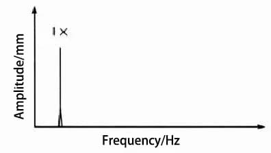
Fig. 1 Typical loosening spectrum diagram of type A
Table 1 Basic Characteristics Reflected by Type A Looseness
| Parameter | Basic characteristics |
| Frequency | The loosening frequency spectrum is dominated by higher 1×-turn frequency vibration |
| Vibration | Generally, the radial vibration is large, especially the vertical vibration is large, and the axial vibration is small or normal |
| Phase | Comparing the vibration in the vertical and horizontal directions, it can be found that the vibration has directivity, and the phase difference is 0 ° or 180 ° |
Notes:
This type of looseness only occurs when the following faults occur:
These looseness issues can also be observed on-site, but the matching problems of internal components can only be detected and confirmed through disassembly and examination.
Treatment measures:
The vibration can be reduced by replacing damaged parts, fixing the fit of incorrect parts, tightening bolts, etc.
The typical frequency spectrum of looseness is depicted in Figure 2, and the fundamental characteristics reflected by the looseness are presented in Table 2.
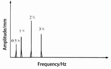
Fig. 2 Typical loosening spectrum diagram of type B
Table 2 Basic Characteristics Reflected by Type B Looseness
| Parameter | Basic characteristics |
| Frequency | Multiple turn frequency harmonics, when the radial 2×-turn frequency amplitude exceeds 50% of the 1×-turn frequency amplitude, it indicates that such a fault occurs. |
| Vibration | The amplitude is somewhat unstable. When the load is high, the vibration increases greatly. |
| Phase | If a strobe lamp is used to collect phase readings, two unstable reference points will usually be displayed. |
Notes:
• Under normal conditions, these vibration symptoms will not occur if there are no other excitation forces.
• If the looseness is caused by the loose bearing of the bearing pedestal or the loose parts on the shaft, the vibration will remain mostly at the 1x- and 2x-speed until it worsens into a pulsation or impact.
In this case, the pulsation will result in the non-linearity of the time domain waveform, leading to many harmonics that are more severe than Type C looseness.
• Sometimes, the failure of the coupling is further exacerbated by the fracture and looseness of the equipment foot, causing wear and looseness in the elastic block of the coupling. This spectrum also displays harmonics that surpass Type C looseness.
This type of looseness encompasses the following faults:
• Loose bearings in the bearing pedestal.
• Excessive internal clearance in the bearings.
• Loose bearing bushes in the bearing seat.
• Loose rotor.
• Loose bearings or running rings, etc.
These issues can be observed by opening the end cover of the bearing pedestal. This type of looseness is directly associated with the bearings and shafts of rotating equipment.
When the looseness is severe, the bearings, shafts, or related mating parts will suffer wear, or in severe cases, the rotating equipment may become completely blocked.
Treatment measures:
It can be solved by replacing the bearing or bushing and adjusting the fit between components.
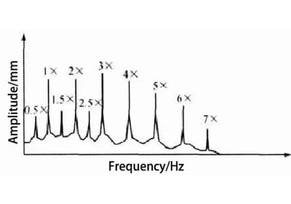
Typical loosening frequency spectrum is shown in Fig. 3, and the basic characteristics reflected by its loosening are shown in Table 3.

Fig. 3 Typical loosening spectrum diagram of type C
Table 3 Basic Characteristics Reflected by Type C Looseness
| Parameter | Basic characteristics |
| Frequency | The harmonics of multiple frequency conversion sometimes reach 10× or even 20×, which are very obvious in the spectrum.If the harmonic amplitude becomes larger, the frequency component with an interval of 1/2 times the frequency will also be generated (i.e. 0.5 ×, 1.5 ×, 2.5 ×). Sometimes there is even 1/3 times of the frequency conversion harmonic. |
| Vibration | This looseness tends to produce highly directional vibration with relatively high amplitude. |
| phase | Generally, the phase measurement of this type of loose fault is somewhat unstable, but if the vibration itself becomes highly directional, the difference between the horizontal and vertical directions will be close to 0 ° or 180 °. |
Notes:
• Looseness may also occur after the component has reached its operating temperature and has undergone thermal expansion.
• The presence of a distinct 1/2x-peak suggests that a more complex loosening issue is present, possibly involving friction.
• When the rotor, such as a pump impeller, is loose, the phase changes after each start.
• The vibration spectrum of this type of looseness, characterized by many 1×-speed harmonics, actually indicates a more severe problem, such as looseness in the bearings and ring running.
This issue can result in shaft clamping and significant equipment failure.


