Optimizing Welding Automation: Robotics and Equipment Selection
Are you curious about how welding automation is transforming modern manufacturing? This article delves into selecting the right robots and equipment for welding projects, highlighting essential considerations like robot models, tooling, and layout. By understanding these aspects, you’ll learn how to enhance productivity, ensure high-quality welds, and optimize the entire welding process. Dive in to uncover how intelligent manufacturing is revolutionizing the industry and what steps you can take to implement effective automation solutions in your own operations.
Intelligent manufacturing has made its way into the manufacturing industry, and automatic production has become an effective way for companies to enhance their influence, expand product scale, and win the market.
The automatic workstation project has evolved from conventional stacking, welding, and handling to data collection and intelligent manufacturing, and has been developed step-by-step.
This post provides an analysis and explanation of the three aspects of the welding automation project, which include preliminary design, fixture description, site layout, and beat.
Selection of welding robot
To successfully execute a robot automatic welding project, it is crucial to have a comprehensive understanding of the selected robot model and its performance. It is essential to consider if there are specific regulations and requirements for the product material information, incoming material status, process requirements, and inspection requirements.
Additionally, it is essential to understand the equipment’s function, technical parameter information, and application environment to provide a comprehensive planning scheme. Typically, a 6-axis robot is used, with the fixture utilizing 7-axis or multi-axis as external axis, specifically designed for robot manufacturing.
Based on the welding process requirements (MIG, MAG, TIG, SUP, CO2, etc.), size parameters (such as arm span length and load capacity), and structural state, the appropriate equipment model should be selected.
For the welding of the lower beam of the elevator using the MAG welding process, the ABB 1410-5/1.44 robot has been selected.
See Table 1 for specific parameter information.
Table 1 welding product information (unit: mm)
Product description
Product information
Weld length
Weld size
length
height
width
Lower beam
1400
276
431
954
a2.5
122
276
431
1100
276
431
It is essential to select the appropriate robot model based on specific parameter and process information. For products with a maximum size of 1400mm, the ABB 1410-5/1.44 robot model has been selected, which can cover the required size range.
In addition, it is necessary to consider whether the robot’s repeated positioning accuracy is within the control range. This is because the repeatability of the robot determines the consistency of the welding process. High repetitive positioning accuracy not only reflects the accuracy of the robot but also ensures that the welding quality meets the required standards. Poor repetitive positioning accuracy can result in unqualified products, leading to losses for the enterprise.
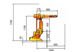
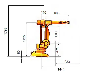
The trajectory diagram and parameter information of the robot are shown in Figure 1.
Project description
Manipulator parameter information
Wrist holding weight
5kg
Maximum arm span radius
1440mm
Number of axes
6 axis
Repeat positioning accuracy
025mm (Comprehensive average value of multiple robots)
Robot version
Standard Edition
Protection level
IP54
Axial motion
Axis
Motion range
Max speed
1
+170° ~ -170°
120°/s
2
+70° ~ -70°
120°/s
3
+170° ~ -65°
120°/s
4
+150° ~ -150°
280°/s
5
+115° ~ -115°
280°/s
6
+300° ~ -300°
280°/s
Power supply: 200 ~ 600V, 50/60hz
Robot size
Base:620mm×450mm
Robot weight
225kg
ambient temperature
-5℃-45℃
Maximum humidity
95%
Maximum noise
70dB(A)
Figure 1 parameter information of robot trajectory diagram
During the initial selection of the robot model, it is crucial to consider layout and origin limitations. To ensure accessibility for welding and avoid decreasing work efficiency, we need to consult the function description table and trajectory diagram of the robot.
Currently, production simulation and testing can be carried out through robot teaching software. This enables the evaluation and confirmation of the welding range of the robot, product space, and position placement during the early stages of the project. By identifying and improving any potential issues caused by robot production in advance, we can optimize the production process.
Description of external equipment
During the early stages of simulation and testing, there is often a lack of evaluation of external equipment such as tooling, external axis, and sliding table. This can lead to excessive energy being expended on the transformation of these components, increasing the project cycle and causing losses for the enterprise.
Therefore, it is essential to evaluate the external equipment, such as tooling, external axis, and sliding table, in advance.
Welding tooling
Welding tooling plays a crucial role in the overall progress of a project.
Tooling design is a subject that requires the accumulation of experience, mechanical and electrical knowledge, and a deep understanding of products. We aim to provide a way to deal with the design of welding tooling.
In general, robots are suitable for standard and low repeatability products for large-scale manufacturing. Therefore, consistency in the design of welding tooling, including the consistency of the robot’s repeated positioning accuracy, clamping sequence, positioning accuracy, stiffness, and positioning requirements, is critical.
It is essential to ensure the accuracy of the welding product’s positioning in the tooling, as well as to control the welding stress and deformation after welding, which requires appropriate stiffness.
Most welding tools are located by pneumatic, hydraulic, electric, or manual support pneumatic structures. With technological advancements, magnetic fixation can also be considered, but it should only be used for special tooling without magnetic bias blowing and selected according to the actual situation.
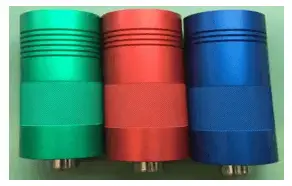
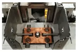
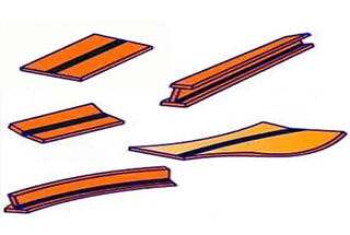
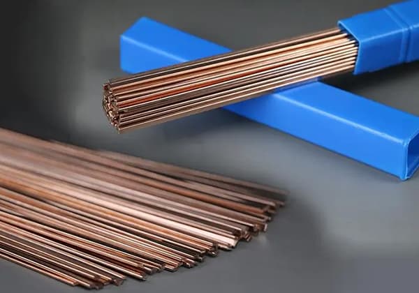
Additionally, red copper and alloy materials are often used to make special gaskets (see Fig. 2 and Fig. 3) to improve the heat dissipation and stiffness of products.
Fig. 2 Special material module
Fig. 3 Copper material module
External shaft positioner
The positioner is used as an external axis of the robot. Its positioning accuracy, turnover, and rotation accuracy directly impact the repeated positioning accuracy and welding quality of the robot, which, in turn, affects the final product quality.
During the pre-design phase of the positioner with welding tooling, the load needs to be considered, including the weight of the tooling and the product being welded. To avoid overweight situations, it’s essential to select reducers, gears, and ring gears with small backlash and high rotation accuracy. This helps to reduce the rotation inertia of the positioner, allowing for a faster acceleration and deceleration response, ultimately improving accuracy requirements.
Table 2 presents the parameter information of the positioner.
Table 2 Parameter information of positioner
Double seat single rotary positioner (set)
Outer axis
ABB external shaft MU200
Load bearing
200Kg
Height of tooling loading table
850mm
Accuracy of positioner
The radius of rotation center is 500mm
Repeat positioning accuracy
±0.15mm
Welding system configuration
The welding system should include the following components, according to the welding project requirements: welding power supply, wire feeder, welding gun, cooling system (some of which are integrated into the welding power supply), gun cleaning system, wire cutting system, and anti-collision system.
If there are specific requirements, additional equipment auxiliary systems can be considered to improve the quality and efficiency of welding. These may include laser position patrol, visual tracking, origin TCP calibration, and other similar systems.
Analysis of the problems existing in the project
Every automation project is likely to encounter problems and challenges. In this post, we have highlighted some of the most common issues that arise during the routine process and explained them.
The welding tooling is manual
Manual tooling is a common production mode used in some enterprises for welding. However, from a manufacturing perspective, the flexibility of humans is higher than that of robots, and human brains have better control than robots.
During welding, welders can adjust the process at any time by observing the weld pool and welding torch trajectory. In contrast, robots follow a predetermined program for welding, which can result in a simple copying of manual tooling and pose challenges in adjustment and tracking.
Moreover, since robots are used for mass production, there is a risk of a large number of bad and rework products, which can lead to inconsistencies in production efficiency.
While the idea for tooling can be learned from manual tooling, it is necessary to consider the strength and repeatability from the perspective of manufacturing needs. This can be achieved through a special process or by changing the tooling design to meet the requirements of robots.
Insufficient weld accessibility
As stated earlier, incomplete identification and delayed tooling design before project evaluation led to difficulties in completing some welds during the welding process. Additionally, some welding positions were not suitable, such as the need to switch from ship-type welding to vertical down welding, resulting in poor welding quality of products.
To address these issues, it is necessary to conduct simulations before welding and have a thorough understanding of robot instructions.
Selection of robot welding process
The robot welding process, including welding parameters and welding sequence, differs from manual welding. Output parameters of the robot are generally stable.
Copying manual welding parameters and processes to the robot may not be suitable, as it can cause welding deformation to increase. Hence, it is crucial to reevaluate the welding process based on project considerations, given the particularity of robot manufacturing.
Management of welding raw materials
The robot is highly sensitive to changes in raw materials. Thus, when using robot welding, we must consider controlling the welding raw materials.
Therefore, it’s crucial for enterprises and project managers to understand that robots are not only capable of replacing manual labor in production.
Conclusion
The robot is extensively used in various industries, and welding robots are one of them. Welding robots have their own unique characteristics compared to other types of robots.
To improve the efficiency and quality of a company’s products and reduce labor intensity through robot workstations, attention needs to be paid to raw material management, equipment selection, process confirmation, personnel training, and other aspects.
However, from an enterprise perspective, preparation and manufacturing of automation solutions is not an overnight process. Its influence and significance are not limited to replacing humans with machines, but also include upgrading the entire industry. This involves investing in technology and experience and returning it with quality and market value.
As the founder of MachineMFG, I have dedicated over a decade of my career to the metalworking industry. My extensive experience has allowed me to become an expert in the fields of sheet metal fabrication, machining, mechanical engineering, and machine tools for metals. I am constantly thinking, reading, and writing about these subjects, constantly striving to stay at the forefront of my field. Let my knowledge and expertise be an asset to your business.
Achieving a flawless weld requires more than just skill; it hinges on mastering the interplay between voltage and current. These two parameters are the lifeblood of welding, dictating everything from…
Have you ever wondered why welded structures sometimes fail despite their robust appearance? This article dives into the hidden challenges of welding, exploring how uneven heating and cooling can lead…
Ever wondered how skyscrapers stand tall or cars stay welded together? This blog uncovers the magic behind electric welding machines. Learn about top manufacturers like Lincoln Electric and Miller Welds,…
Have you ever wondered which welding equipment brands are leading the industry today? This article explores the top ten welding machine manufacturers, highlighting their innovations, global presence, and unique strengths.…
Have you ever wondered how to calculate the consumption of welding rods accurately? In this blog post, we'll explore the methods and formulas used by industry experts to estimate welding…
Have you ever wondered how to perfect your TIG welding technique? Choosing the right parameters is crucial for achieving strong, clean welds. In this article, we’ll explore the essentials: selecting…
Why is welding high carbon steel such a challenge? This article delves into the unique difficulties associated with this material, such as its tendency to form brittle martensite, leading to…
Imagine trying to weld a material so strong that it resists wear and tear, yet so tricky that improper technique could lead to catastrophic failure. This is the challenge faced…
Why can low-carbon steel be welded easily while high-carbon steel poses challenges? This article explores the weldability of different types of carbon steel, highlighting how varying carbon content impacts the…