Have you ever wondered what makes welding stainless steel and heat-resistant steel so challenging? This article breaks down the complexities of welding these materials, from the unique properties of different stainless steel types to the best practices for achieving strong, corrosion-resistant welds. By the end, you’ll understand key techniques for avoiding common issues like cracking and embrittlement, ensuring your welds are both durable and reliable.
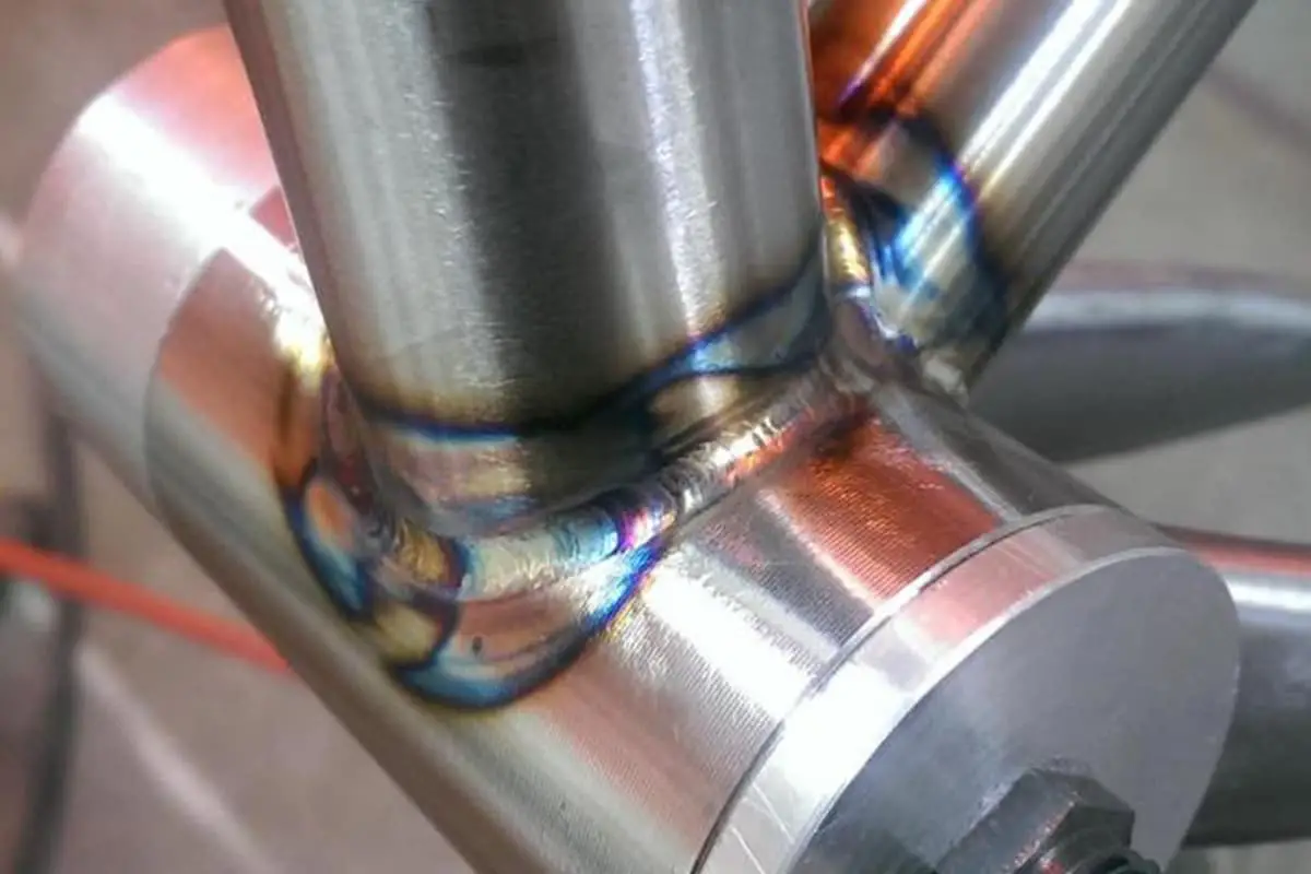
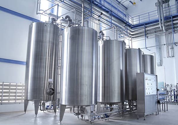
Stainless steel refers to a type of steel that remains in a passivated state on the surface by adding alloying elements such as chromium, enabling it to resist corrosion from the atmosphere and certain media, and possessing good chemical stability.
When the chromium content in stainless steel exceeds 12%, a dense oxide film can quickly form on the surface, resulting in a significant increase in the steel’s electrode potential and corrosion resistance in oxidizing environments.

There are several classification methods for stainless steel. According to the structure type, it can be divided into ferritic stainless steel, austenitic stainless steel, martensitic stainless steel, duplex stainless steel, and precipitation-hardening stainless steel.
Austenitic stainless steel is the most widely used and diverse type of stainless steel. Currently, austenitic stainless steel can be roughly divided into two types: Cr18-Ni8 type, such as 0Cr18Ni9, 00Cr19Ni10, 0Cr19Ni10NbN; and Cr25-Ni20 type, such as 0Cr25Ni20. Ferritic stainless steel is also widely used, with Cr13 and Cr17 types, such as 0Cr13Al, 1Cr17, 00Cr18Mo2, mainly used in environments with less severe corrosion conditions.
Martensitic stainless steel primarily utilizes the Cr13 type, such as 0Cr13, 1Cr13, 2Cr13, 0Cr13Ni4Mo. Duplex stainless steel is a stainless steel with a dual-phase microstructure consisting of austenite and ferrite, with both phases occupying a significant proportion, such as 0Cr26Ni5Mo2, 00Cr18Ni5Mo3Si2.
Precipitation-hardening stainless steel is a type of stainless steel that incorporates hardening elements either individually or in combination, obtaining high strength, high toughness, and good corrosion resistance through appropriate heat treatment.
Compared to other types of stainless steel, welding austenitic stainless steel is relatively easy. The main issues that may arise during welding are as follows: high susceptibility to heat cracking in the weld and heat-affected zone, precipitation of chromium carbides in the joint leading to decreased corrosion resistance, and potential for 475°C embrittlement or sigma phase embrittlement when the joint contains a high amount of ferrite.
(1) Heat cracking in welded joints
Austenitic stainless steel is highly susceptible to heat cracking, and there is a possibility of crack formation in both the weld and heat-affected zone. This is most commonly seen as solidification cracks in the weld, but can also occur as liquation cracks in the heat-affected zone or between multiple layers of weld metal. The cracks can be categorized as solidification cracks, liquation cracks, or high-temperature low-plasticity cracks.
To prevent heat cracking in austenitic stainless steel, the main measures include:
1) Metallurgical measures:
Strict control of harmful impurities in the weld metal. The higher the nickel content in the steel, the more important it is to control the levels of sulfur, phosphorus, boron, selenium, and other harmful elements to prevent heat cracking. For single-phase austenitic welds, the addition of appropriate amounts of manganese, small amounts of carbon and nitrogen, and reducing the silicon content can improve the crack resistance of the weld.
Adjusting the chemical composition of the weld. Creating a duplex structure of austenite and ferrite in the weld metal effectively prevents the formation of heat cracks. For example, the presence of a small amount of ferrite phase in the microstructure of an 18-8 steel weld greatly improves its crack resistance. Common elements that promote ferrite formation include chromium, molybdenum, vanadium, etc.
These metallurgical measures primarily involve adjusting the chemical composition of the welding material.
2) Process measures:
Minimize overheating of the weld pool to prevent the formation of coarse columnar grains. Therefore, it is advisable to use small heat input and small cross-section welds. In multi-pass welding, the interpass temperature should not be too high to avoid overheating of the weld. During the welding process, the welding rod should not be oscillated, and narrow and fast welding techniques should be employed.
Sensitization temperature range: Austenitic stainless steel is most sensitive to intergranular corrosion when heated to 400-800°C. This temperature range is known as the sensitization temperature range.
(2) Corrosion resistance of welded joints:
Welded joints can experience intergranular corrosion, knife-line corrosion, and stress corrosion during service.
To prevent intergranular corrosion in welded joints, the following measures can be taken:
1) Metallurgical measures:
Create a duplex structure of austenite and ferrite in the weld metal, with the volume fraction of ferrite ranging from 4% to 12%. Within this range, the weld metal not only exhibits improved resistance to intergranular corrosion and stress corrosion, but also enhances its resistance to heat cracking.
Introduce stabilizing elements into the weld metal that have a greater affinity for carbon than chromium, such as titanium, niobium, tantalum, and zirconium.
Minimize the carbon content in the weld metal to prevent intergranular corrosion. The carbon content should be reduced to below the solubility limit of carbon in stainless steel at room temperature, making it impossible for carbon to react with chromium and form Cr23C6, thereby eliminating the chromium-depleted zone at the grain boundaries. When the mass fraction of carbon in the weld metal is less than 0.03%, the weld metal exhibits improved resistance to intergranular corrosion.
As mentioned above, in order to have the appropriate types and quantities of alloying elements in the weld metal, it is necessary to start with the welding material and select welding electrodes, fluxes, and wires that meet the aforementioned metallurgical conditions. This is essential to achieve the goal of preventing intergranular corrosion in the weld metal.
2) Process measures:
Choose an appropriate welding method that minimizes heat input and reduces the time the welded joint stays in the sensitization temperature range. For thin and small regular joints, techniques such as electron beam welding, plasma arc welding, and tungsten inert gas (TIG) welding with concentrated energy should be used.
For medium-thickness plate welds, the use of metal inert gas (MIG) welding with melting electrode is suitable. For thick plate welds, submerged arc welding and shielded metal arc welding are commonly used methods, while gas welding is not recommended.
When determining welding parameters, it is important to ensure weld quality while using low welding current and the fastest welding speed possible.
By selecting the appropriate welding method and optimizing the welding parameters, the goal is to minimize the time spent in the sensitization temperature range and reduce the risk of intergranular corrosion in the welded joint while ensuring weld quality.
In terms of operations, it is advisable to use narrow weld seams and multiple passes for multi-layer welds. After each weld pass or layer, it is important to allow the welded joint to cool to room temperature before proceeding to the next pass or layer. During the welding process, the welding material should not be oscillated in the molten pool. When welding pipes using argon arc welding as the root pass, it is possible to perform fusion welding without adding filler material.
If conditions permit, purging the inside of the pipe with argon gas can protect the molten pool from oxidation, accelerate the cooling rate of the weld, and facilitate the formation of the back weld. For welds exposed to corrosive media, it is preferable to perform the final weld if conditions allow, in order to minimize the number of times the weld is heated by the corrosive medium.
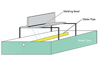
Rapid cooling in the heat-affected zone is achieved by forced cooling. For regular welds, if conditions allow, a pure copper backing can be used, and water or protective gas can be circulated through the copper backing to facilitate forced cooling. This helps prevent intergranular corrosion in the welded joint.
This is because at lower heating temperatures (below 400°C) or short heating times, it is less conducive to carbon diffusion and the formation of chromium carbides, thereby avoiding the chromium-depleted zone.
The process of solution treatment or stabilization treatment is carried out. After solution treatment, austenitic stainless steel has the lowest strength and hardness, and the best corrosion resistance, which is an important means to prevent intergranular corrosion.
Sensitized austenitic stainless steel can be further eliminated by solution treatment. The stabilization treatment is generally heated at a temperature of 850-900℃ and kept for 2-4 hours. Stabilization treatment can also be used to eliminate the small knowledge produced by sensitization heating.
Solution treatment and stabilization treatment: Solution treatment is a process in which the welded joint is heated to a temperature range of 1050-1150℃, kept for a certain period of time, and then rapidly cooled within the range of 800-400℃.
Stabilization treatment is a heat treatment process designed for austenitic stainless steel containing stabilizers, generally heated to 850-900℃ and kept for 2-4 hours.
2) Knife-line corrosion.
Knife-line corrosion, also known as knife-edge corrosion or simply knife corrosion, is a specific form of intergranular corrosion that occurs only in the welded joints of austenitic stainless steel containing stabilizing elements such as Ti and Nb. The corrosion occurs along the fusion line in the overheated zone of the Heat Affected Zone (HAZ). Due to its narrow width (generally 1.0-1.5mm in arc welding), it takes on the appearance of a cut made by a knife, hence the name knife-line corrosion. Measures to prevent knife-line corrosion include:
Firstly, reducing the carbon content in the base material. This is an effective measure to prevent knife-line corrosion, as ultra-low carbon austenitic stainless steel welded joints do not exhibit knife-line corrosion.
Secondly, adopting a reasonable welding process. While ensuring the quality of the weld, it is advisable to choose a smaller heat input to reduce the dwell time of the overheated zone at high temperatures, and to avoid the occurrence of “mid-temperature sensitization” during the welding process.
In double-sided welding, the weld in contact with the corrosive medium should be applied as the final weld if possible. If not feasible, welding parameters and weld shape should be adjusted to minimize the re-sensitization heating of the overheated zone in contact with the corrosive medium.
Forced cooling methods can be employed during or after welding to achieve rapid cooling of the welded joint. Post-weld correction can be carried out using cold correction methods. For welded joints with high requirements for corrosion performance, post-weld stabilization treatment or solution treatment may be necessary.
3) Stress corrosion cracking.
Stress corrosion cracking is a form of damage that occurs when tensile stress and specific corrosive media act together. It is a highly sensitive and frequently occurring corrosion failure mode in austenitic stainless steel. Accidents caused by stress corrosion cracking account for more than 60% of all corrosion-related failures.
Austenitic stainless steel is prone to deformation during welding due to its poor thermal conductivity, high linear expansion coefficient, and low yield strength. When the welding deformation is restricted, significant residual welding stress will inevitably remain in the welded joint, accelerating the action of the corrosive medium.
As a result, stress corrosion cracking is common in welded joints of austenitic stainless steel. It is one of the most challenging issues to address in welding austenitic stainless steel, especially in chemical equipment where stress corrosion cracking frequently occurs.
Measures to prevent stress corrosion cracking include:
Firstly, designing the welding joint in a rational manner to avoid the accumulation of corrosive media in the welding joint area and reduce or eliminate stress concentration in the welding joint.
Secondly, eliminating or reducing residual stress in the welding joint. Post-weld stress relief treatment is a commonly used process measure, with a heating temperature between 850-900℃ yielding the most ideal stress relief effect.
Mechanical methods such as surface polishing, shot peening, and hammering can also be employed to induce surface compressive stress. In structural design, butt joints should be used as much as possible to avoid cross-welds, and single V-shaped grooves can be replaced with double Y-shaped grooves.
Thirdly, selecting the correct material. Materials with low sensitivity to stress corrosion cracking should be chosen based on the characteristics of the medium. This includes not only the base material, but also the welding consumables, as they can greatly affect the resistance to stress corrosion cracking.
(3) Embrittlement of Welded Joints
There are two main forms of embrittlement in welded joints of austenitic stainless steel: low-temperature embrittlement and σ-phase embrittlement.
1) Low-temperature embrittlement of weld metal:
In the case of austenitic stainless steel welded joints, corrosion resistance or oxidation resistance is not always the most critical property. When used at low temperatures, the plasticity and toughness of the weld metal become crucial. To meet the requirements of low-temperature toughness, a single austenitic microstructure is desired in the weld metal, avoiding the presence of δ-ferrite. The presence of δ-ferrite always degrades low-temperature toughness.
2) σ-phase embrittlement of welded joints:
The σ-phase is a brittle intermetallic compound that mainly accumulates at the grain boundaries of columnar crystals. The occurrence of σ-phase embrittlement is related to the degree of alloying in austenitic stainless steel. For austenitic stainless steel with high alloying elements such as Cr and Mo, σ-phase can easily precipitate. Cr and Mo have a significant effect on the formation of σ-phase.
Increasing the nickel content, which is an alloying element in austenitic stainless steel, can effectively suppress the formation of σ-phase during the welding process, thus preventing the embrittlement of welded joints. This is an effective metallurgical measure for preventing embrittlement in welded joints.
Duplex stainless steel exhibits good weldability, and with the use of appropriate welding materials, welding hot cracking and cold cracking can be avoided. The mechanical properties of the welded joint can generally meet the performance requirements of the welded structure.
The welded joint also demonstrates good resistance to stress corrosion cracking, and its resistance to pitting and crevice corrosion is superior to that of austenitic stainless steel, while its resistance to intergranular corrosion is comparable to that of austenitic stainless steel.
However, the near-weld zone of the welded joint is influenced by the welding heat cycle, leading to inevitable coarsening of the ferrite grains in the overheated zone, thereby reducing the corrosion resistance in that area.
(1) Selection of Welding Methods:
Both austenitic stainless steel and duplex stainless steel can be welded using various fusion welding methods, such as shielded metal arc welding (SMAW), tungsten inert gas (TIG) welding, gas metal arc welding (GMAW), submerged arc welding (SAW), and plasma arc welding.
1) Shielded Metal Arc Welding (SMAW):
SMAW is the most commonly used welding method, known for its flexibility and convenience. To enhance resistance against hot cracking, it is recommended to use basic-coated electrodes. For welds that require high corrosion resistance and good surface appearance, electrodes with good process performance, such as titanium-calcium type coatings, are preferred.
2) Tungsten Inert Gas (TIG) Welding:
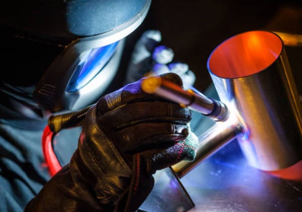
TIG welding is an ideal method for welding austenitic stainless steel and duplex stainless steel because it minimizes alloy element burn-off during the welding process, resulting in a clean and slag-free weld surface with good weld bead formation. Additionally, TIG welding has a lower heat input, making it particularly suitable for welding heat-sensitive austenitic and duplex stainless steels.
3) Submerged Arc Welding (SAW):
SAW is a highly efficient welding method characterized by high heat input, large weld pool size, and slower cooling and solidification rates. This method increases the susceptibility to hot cracking. SAW has a wide range of dilution rates in the base metal (10% to 75%), which significantly affects the composition of the weld metal, especially in controlling the ferrite content in the weld microstructure.
4) Plasma Arc Welding:
Plasma arc welding is also a fusion welding method with inert gas protection, using a high-energy density plasma arc as the heat source. It offers advantages such as concentrated energy, small heat-affected zone, fast welding speed, high heat utilization efficiency, and narrow heat-affected zone. Under wind-free conditions, plasma arc welding is beneficial for improving the corrosion resistance and enhancing the microstructure of the welded joint.
Gas metal arc welding, such as MIG welding, is also widely used. CO2 gas shielded welding with flux-cored wire is also applied in stainless steel welding.
(2) Selection of Welding Materials
The principle for selecting welding materials for austenitic stainless steel is to generally choose materials with similar or identical chemical compositions to the base metal.
However, it is also necessary to consider the overall mechanical properties, corrosion resistance, crack resistance, and high-temperature resistance of the welded joint, based on the specific usage conditions. Table 5-21 provides examples of recommended selection of various stainless steel welding materials.
Table 5-21: Examples of Recommended Stainless Steel Welding Materials
| Steel grade | Welding electrode for arc welding | Submerged arc welding | Argon arc welding | ||
| Model | grade | welding wire | flux | ||
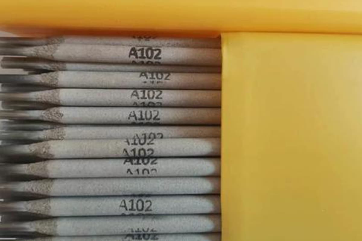
| 0Cr18Ni9 | E308-16 | A102 | H0Cr21Ni10 | HJ260 | H0Cr21Ni10 |
| 0Cr18Nil0Ti1Cr18Ni9Ti | E347-16 | A132 | H0Cr21Ni10Ti | HJ260 | H0Cr21Ni10Ti |
| 0Cr17Nil2Mo2 | E316-16E316-15 | A202A207 | H0Cr19Ni12Mo2 | HJ260 | H0Cr19Ni12Mo2 |
| 00Cr19Ni10 | E308L-16 | A002 | H00Cr21Ni10 | HJ260 | H00Cr21Ni10 |
| 00Cr17Nil4Mo2 | E316L-16 | A022 | |||
(3) Key points for welding austenitic stainless steel and duplex stainless steel. The welding process for austenitic stainless steel and duplex stainless steel is as follows:
1) Pre-weld preparation:
a) Material cutting and groove preparation: Due to the high chromium content in austenitic stainless steel and duplex stainless steel, it is difficult to cut with an oxyacetylene flame. Mechanical cutting, air carbon arc cutting, plasma arc cutting, or other methods can be used for material cutting and groove preparation.
b) Pre-weld cleaning: To ensure welding quality, the groove and the surface within a range of 20-30mm on both sides of the groove should be cleaned thoroughly. If there is oil contamination, organic solvents such as acetone or alcohol can be used for cleaning. For weldments with high surface quality requirements, a slurry made of white chalk powder can be applied within a suitable range to prevent spatter from damaging the steel surface. During handling, groove preparation, assembly, and positioning welding, care should be taken to avoid damaging the steel surface, as it may reduce the corrosion resistance of the product. Arc striking and using sharp tools to scratch the steel plate surface randomly are not allowed.
Positioning welding:
During positioning welding, the welder must use the same welding material and specifications as the actual welding process. The height of the weld inside the groove generally should not exceed 2/3 of the groove depth. If defects such as cracks occur in the positioning weld, it must be removed and re-welded.
The welding materials should undergo specified drying treatment.
The arc should be struck inside the groove, and a single pass of fusion should be achieved. The arc should be extinguished to fill the crater.
When welding stainless steel, the welding current should be 10% to 20% lower compared to welding low carbon steel. Short arc, fast welding, and straight travel should be employed. Simultaneously, interpass temperature should be controlled, generally kept below 100°C. To prevent excessive interpass temperature, measures such as backside water cooling can be implemented if necessary.
For multi-layer and multi-pass welding, after completing each pass, the slag should be removed, and the appearance should be checked for any surface defects before proceeding to the next pass. The starting and ending positions of adjacent layers should be staggered.
For concentrated welds, methods such as skip welding, segmented symmetrical welding, or back-stepping can be used to reduce welding distortion and overheating.
When full penetration double-sided welding is required, the root of the weld must be cleaned. If carbon arc air gouging is used for root cleaning, it must be ground with a grinding wheel until there are no oxides or carbide layers present. For ultra-low carbon stainless steel or when specific requirements exist, root cleaning must be done using grinding wheel grinding or mechanical methods.
Welds in contact with the medium should be welded last to prevent a decrease in corrosion resistance of the weld.
Welds in contact with the medium should be welded last to prevent a decrease in corrosion resistance of the weld.
3) Post-weld heat treatment:
In general, austenitic stainless steel and duplex stainless steel do not require post-weld heat treatment. However, if the welded joint becomes embrittled or if there is a need to further improve its corrosion resistance, solution treatment, stabilization treatment, or stress relief treatment can be chosen as needed.
4) Post-weld cleaning:
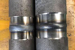
Stainless steel welds must undergo pickling and passivation treatment. Pickling aims to remove the oxide scale on the surface of the weld and the heat-affected zone, while passivation aims to re-form a layer of colorless, dense oxide film on the pickled surface, providing corrosion resistance.
(1) Characteristics of welding ferritic stainless steel:
Currently, ferritic stainless steel can be divided into ordinary ferritic stainless steel and ultra-pure ferritic stainless steel. The main issues in welding ferritic stainless steel are the reduction of plasticity and toughness in the weld joint, embrittlement in the heat-affected zone, and intergranular corrosion in the weld joint.
(2) Welding methods and materials for ferritic stainless steel:
Welding of ferritic stainless steel should use low heat input welding methods, such as shielded metal arc welding, gas tungsten arc welding, or plasma arc welding. The selection of welding materials should follow the principle of matching the composition of the base metal. Alternatively, welding materials for austenitic stainless steel can be used, eliminating the need for preheating before welding and post-weld heat treatment.
(3) Key points of welding process:
The key points for welding ferritic stainless steel are as follows:
1) Preheating:
Preheating temperature should be around 100-200°C. The purpose is to put the material being welded in a better state of toughness and reduce the stress in the welding joint. As the chromium content in the steel increases, the preheating temperature should also be increased accordingly.
2) Post-weld heat treatment:
After welding, the joint area should be annealed at a temperature of 750-800°C. This treatment allows for the complete precipitation of oversaturated carbon and nitrogen, replenishment of chromium into depleted chromium areas, to restore its corrosion resistance. It also improves the plasticity of the welded joint. It is important to note that rapid cooling should be applied after annealing to prevent the formation of 475°C brittleness.
Other process requirements are similar to those of austenitic stainless steel.
(1) Characteristics of welding martensitic stainless steel:
Martensitic stainless steel can be divided into Cr13 martensitic stainless steel, low carbon martensitic stainless steel, and super martensitic stainless steel. Common martensitic stainless steels have a tendency for hardening during quenching, and the higher the carbon content, the greater the tendency for hardening. Therefore, the common issues in welding martensitic stainless steel are embrittlement in the heat-affected zone and cold cracking.
(2) Selection of welding methods:
Common welding methods such as shielded metal arc welding, gas tungsten arc welding, consumable electrode gas shielded welding, and plasma arc welding can all be used for welding martensitic stainless steel. Shielded metal arc welding is the most commonly used method.
(3) Selection of welding materials:
For Cr13 martensitic stainless steel, overall, its weldability is poor. Therefore, besides using welding materials that have similar chemical composition and mechanical properties as the base metal, for martensitic stainless steel with higher carbon content, austenitic-type welding materials are often used to improve the plasticity and toughness of the weld joint and prevent the occurrence of welding cracks. Commonly used welding electrodes can be found in Table 5-22.
Table 5-22: Selection of Welding Materials, Preheating, and Post-Weld Heat Treatment for Martensitic Stainless Steel
| Steel grade | Welding electrode | Welding wire | Preheating temperature, interpass temperature/°C | Post-weld heat treatment temperature/°C | ||
| Model | grade | solid core | flux core | |||
| 1Crl32Crl3 | E410-16 E410-15 | G202G207 | H1Cr13H2Cr13 | E410T | 250~300 | 700~730 Tempering |
| E308-16 E308-15 E316-16 E316-15 E310-16 E310-15 | A102 A107 A202 A207 A402 A407 | No heat treatment required (preheating up to 200°C for thick and large components) | No heat treatment required | |||
| 1Crl7Ni2 | E130-16 | G302 | H0Cr24Ni13 | 200 | 750~800Tempering | |
| E430-15 | G307 | |||||
| E309-16 | A302 | No heat treatment required | No heat treatment required | |||
| E309-15 | A307 | |||||
| E310-16 | A402 | |||||
| E310-15 | A407 | |||||
(4) Key points of welding process:
The key points for welding martensitic stainless steel are as follows:
1) Preheating and post-weld heat treatment:
Preheating temperature is generally between 100-350°C, and it increases with the carbon content. For weld joints with high carbon content or high restraint, necessary post-weld heat treatment measures should be taken before the heat treatment to prevent the occurrence of hydrogen-induced cracking. For example, when welding low alloy steel with austenitic stainless steel, proper welding techniques should be applied. Refer to Table 5-22 for details.
2) Post-weld heat treatment:
Post-weld heat treatment for martensitic stainless steel includes tempering and full annealing. To achieve the lowest hardness, such as for subsequent machining after welding, full annealing can be used with an annealing temperature between 830-880°C, holding for 2 hours, followed by furnace cooling to 595°C and then air cooling.
Tempering temperature is generally between 650-750°C, and the holding time is determined based on 2.4 min/mm, with a minimum holding time of 1 hour, followed by air cooling. Refer to Table 5-22 for examples.
1. A chemical machinery factory is producing a wood phenol measuring tank.
The main material is 0Cr18Ni9 austenitic stainless steel with a thickness of 8mm. The longitudinal and circumferential seams of the cylinder body are welded using shielded metal arc welding with butt joints and V-shaped beveled edges with rounded corners. The welding process can be found in Table 5-23.
| Welding Process Card for Joints | Number | ||
Joint Diagram | Base material | 0Cr18Ni9 | 0Cr18Ni9 |
| Base material thickness | 8mm | 8mm | |
| Welding position | Flat position | ||
| Welding technique | Straight bead | ||
| Preheating temperature | Room temperature | ||
| Interpass temperature | ≤100℃ | ||
| Welding sequence | |
| 1 | Check the dimensions and surface quality of the bevel. |
| 2 | Clean the bevel and its surrounding area from any oil or dirt. Apply a layer of white chalk powder paste on both sides of the bevel. |
| 3 | Perform the initial tack welding from the outer side, with a length of 30-50mm. |
| 4 | Weld the inner layers 1-3. |
| 5 | After carbon arc air gouging and grinding the root from the outer side, use a grinding wheel to smooth it. |
| 6 | Weld the outer layer. |
| 7 | Clean any spatter after welding. |
| 8 | Inspect the appearance. |
| 9 | Perform non-destructive testing as required. |
Welding Specification Parameters
| Passes | Welding Method | Welding Material Grade | Welding Material Specification | Types of Current and Polarity | Welding Current (Ampere) | Arc Voltage (Volt) | Welding Speed (mm/per pass) | Remarks |
| 1 | SMAW | A102 | 3.2 | DCEP | 80~110 | 22~24 | 90~130 | |
| 2~4 | SMAW | A102 | 4.0 | DCEP | 130~160 | 22~24 | 130~170 |
2. For the butt weld of the same product’s nozzle, tungsten inert gas (TIG) welding is used. It is a single-sided welding process with double-sided formation. The welding process can be found in Table 5-24.
Table 5-24: Welding Process Card for 0Crl8Ni9 Tungsten Inert Gas Arc Welding Joint
| Welding Process Card for Joints | Number | ||
Joint Diagram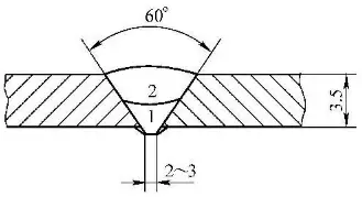 | Base material | 0Cr18Ni9 | 0Cr18Ni9 |
| Base material thickness | 3.5mm | 3.5mm | |
| Welding position | Flat Weld | ||
| Welding technique | Straight Weld Bead | ||
| Preheating temperature | Room Temperature | ||
| Interpass temperature | ≤100℃ | ||
| Tungsten Electrode Diameter | Φ2.5mm | ||
| Nozzle Diameter | Φ16mm | ||
| Welding Sequence | |
| 1 | Check groove dimensions and surface quality. |
| 2 | Remove oil and dirt from the groove and its surroundings. |
| 3 | Perform tack welding with the first layer of welding process from the outside, with a length of 10-15mm. |
| 4 | Weld the first to second layers on the outer side. |
| 5 | Perform visual inspection. |
| 6 | Perform non-destructive testing. |
Welding Specification Parameters
| Passes | Welding Method | Welding Material Grade | Welding Material Specification | Types of Current and Polarity | Welding Current (Ampere) | Arc Voltage (Volt) | Welding Speed (mm/per pass) | Remarks |
| 1~2 | GTAW | H0Cr21Nil0 | Φ2.5 | DCEN | 80~110 | 10~12 | 50~80 |
3. A certain company is manufacturing a steam mixing tank with a material of 00Cr17Ni14Mo2. The welded joint requires a fully penetrated structure. The welding process involves using tungsten inert gas arc welding for sealing the bottom, and electrode arc welding for filling and covering. It is a single-side welding and double-side forming process. For specific details, please refer to the provided documentation.
Table 5-25: Welding Process Card for 00Cr17Ni14Mo2 Butt Joint
| Welding Process Card for Joints | Number | |||
Joint Diagram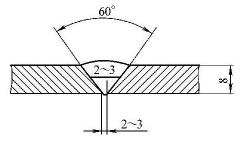 | Base material | 00Cr17Ni14Mo2 | 00Cr17Ni14Mo2 | |
| Base material thickness | 8mm | 8mm | ||
| Welding position | Flat Weld | |||
| Welding technique | Straight Weld Bead | |||
| Preheating temperature | Room Temperature | |||
| Interpass temperature | ≤150℃ | |||
| Tungsten Electrode Diameter | Φ2.5mm | Protective Gas | Ar | |
| Nozzle Diameter | Φ16mm | Gas Flow Rate (L/min) | 8~10 | |
| Welding Sequence | |
| 1 | Check groove dimensions and surface quality. |
| 2 | Remove oil and dirt from the groove and its surroundings. Brush white chalk paste within a 100mm range on both sides of the groove. |
| 3 | Perform tack welding with the first layer of welding process from the outside, with a length of 5-15mm. |
| 4 | Weld the first to third layers. |
| 5 | Clean slag and spatters after welding. |
| 6 | Perform visual inspection. |
| 7 | Perform non-destructive testing. |
Welding Specification Parameters
| Passes | Welding Method | Welding Material Grade | Welding Material Specification | Types of Current and Polarity | Welding Current (Ampere) | Arc Voltage (Volt) | Welding Speed (mm/per pass) |
| 1 | GTAW | H00Crl9Nil2Mo2 | Φ2.5 | DCEN | 80~110 | 10~12 | 50~80 |
| 2 | SMAW | A022 | Φ3.2 | DCEP | 80~110 | 21~23 | 90~130 |
| 3 | SMAW | A022 | Φ4.0 | DCEP | 130~160 | 22~24 | 130~170 |
4. A chemical equipment manufacturing plant is producing a pressure regeneration tower with a material of 0Cr18Ni9. The welding process used is submerged arc welding.
| Welding Process Card for Joints | Number | ||
Joint Diagram | Base material | 0Cr18Ni9 | 0Cr18Ni9 |
| Base material thickness | 14mm | 14mm | |
| Welding position | Flat Weld | ||
| Welding technique | Straight Weld Bead | ||
| Preheating temperature | Room Temperature | ||
| Interpass temperature | ≤150℃ | ||
| Welding Sequence | |
| 1 | Check groove dimensions and surface quality. |
| 2 | Remove oil and dirt from the groove and its surroundings. Apply white chalk paste on both sides of the groove. |
| 3 | Perform tack welding with the electrode arc welding process using the same product from the outside, with a length of 30-50mm. |
| 4 | Weld the first to second layers on the inner side. |
| 5 | Remove excess root with carbon arc gouging from the outside, and grind with a grinding wheel. |
| 6 | Weld the third layer on the outer side. |
| 7 | Clean slag after welding. |
| 8 | Perform visual inspection. |
| 9 | Perform non-destructive testing. |
Welding Specification Parameters
| Passes | Welding Method | Welding Material Grade | Welding Material Specification | Types of Current and Polarity | Welding Current (Ampere) | Arc Voltage (Volt) | Welding Speed (mm/per pass) |
| 1 | SAW | H0Cr21Nil0 SJ601 | Φ4.0 | DCEP | 450~500 | 31~36 | 24~28 |
| 2~3 | SAW | H0Cr21Ni10 SJ601 | Φ4.0 | DCEP | 130~160 | 31~36 | 24~28 |
Heat-resistant steel is an iron-based alloy that exhibits excellent thermal strength, oxidation resistance, and corrosion resistance in high-temperature environments.
Heat-resistant steel can be classified into low-alloy, medium-alloy, and high-alloy heat-resistant steels based on the mass fraction of alloying elements. Heat-resistant steels with a total mass fraction of alloying elements below 5% are referred to as low-alloy heat-resistant steels, which include ferritic heat-resistant steels and bainitic heat-resistant steels.
Heat-resistant steels with a total mass fraction of alloying elements between 6% and 12% are known as medium-alloy heat-resistant steels. Alloy steels with a total mass fraction of alloying elements above 13% are classified as high-alloy heat-resistant steels.
Heat-resistant steels are widely used in conventional thermal power plants, nuclear power plants, petroleum refining equipment, hydrocracking units, synthetic chemical containers, aerospace instruments, and other high-temperature processing equipment. Among them, low-alloy heat-resistant steels are particularly common.
The basic requirements for the welding performance of heat-resistant steel joints depend on the operating conditions of the equipment, the manufacturing process, and the complexity of the welded structure.
In order to ensure the long-term safe operation of the heat-resistant steel welded structure under high temperature, high pressure, and various complex media, the performance of the welded joints must meet the following requirements:
(1) Equivalent strength and ductility of the joint: Heat-resistant steel welded joints should not only have similar room temperature and short-term strength as the base metal but also have comparable long-term strength at high temperatures.
(2) Hydrogen resistance and oxidation resistance of the joint: Heat-resistant steel welded joints should have similar hydrogen resistance and high-temperature oxidation resistance as the base metal. To achieve this, the mass fraction of alloying elements in the weld metal should be similar to that of the base metal.
(3) Stability of joint microstructure: Heat-resistant steel welded joints, especially thick-walled joints, undergo prolonged and repeated heat treatments during the manufacturing process. During operation, they are subjected to long-term high temperature and high-pressure conditions. To ensure the stability of joint performance, the microstructure of each zone of the joint should not undergo significant changes that could lead to embrittlement or softening.
(4) Resistance to brittle fracture: Although heat-resistant steel welded structures operate at high temperatures, for pressure vessels and pipelines, the final inspection is usually conducted at room temperature using a hydraulic or pneumatic pressure test at 1.5 times the working pressure. Before commissioning or after maintenance, high-temperature pressured equipment undergoes a cold start-up process. Therefore, heat-resistant steel welded joints should have a certain resistance to brittle fracture.
(5) Physical homogeneity of low-alloy heat-resistant steel joints: Low-alloy heat-resistant steel welded joints should have physical properties that are essentially the same as the base metal. The thermal expansion coefficient and thermal conductivity of the joint material directly determine the thermal stress on the joint during high-temperature operation. Excessive thermal stress can have a detrimental effect on the joint’s lifespan.
(1) Characteristics of welding medium and low alloy heat-resistant steel: Medium and low alloy heat-resistant steels are a type of alloy steel primarily composed of Cr-Mo as the main alloying elements.
Their welding process has the following characteristics:
Firstly, these steels have varying degrees of hardenability based on their alloy content, and the weld metal and the heat-affected zone may form microstructures sensitive to cold cracking.
Secondly, most heat-resistant steels contain elements such as Cr, Mo, V, Nb, and Ti, which form strong carbides, resulting in varying degrees of susceptibility to reheat cracking (also known as stress-relief cracking) in the heat-affected zone.
Finally, certain heat-resistant steel welded joints may exhibit temper brittleness when the total content of harmful residual elements exceeds the permissible limit.
1) Hardenability and susceptibility to cold cracking of quenchable steels:
The hardenability of quenchable steels depends on their carbon content, alloying elements, and their respective quantities. The main alloying elements in low-alloy heat-resistant steels, such as chromium and molybdenum, significantly enhance the hardenability of the steel.
If the cooling rate during welding is too fast, sensitive microstructures like martensite and upper bainite, which are prone to cold cracking, may form in the weld and heat-affected zone. The higher the chromium content and the faster the cooling rate, the higher the maximum hardness of the joint, leading to a significant increase in susceptibility to cold cracking.
2) Reheat cracking tendency (elimination of stress cracking):
The reheat cracking of low-alloy heat-resistant steel weld joints mainly depends on the characteristics and content of carbide-forming elements in the steel, as well as the welding heat input.
To prevent the formation of reheat cracks, the following metallurgical and process measures can be taken:
Strictly control the alloy composition in the base material and welding material that exacerbates reheat cracking. The content of alloy elements such as V, Ti, and Nb should be controlled within the lowest permissible range while ensuring the thermal strength of the steel.
Select welding filler materials with higher high-temperature plasticity than the base material.
Properly increase the preheating temperature and interpass temperature.
Adopt low heat input welding methods and processes to narrow the width of the overheated zone of the weld joint and restrict grain growth.
Choose appropriate heat treatment specifications to minimize the insulation time in the sensitive temperature range.
Design the joint form in a reasonable manner to reduce the constraint of the joint.
3) Tempering brittleness:
The gradual embrittlement phenomenon that occurs in chromium-molybdenum steel and its welded joints during long-term operation in the temperature range of 370-565°C is called tempering brittleness.
This embrittlement is attributed to the diffusion segregation of trace elements such as P, As, Sb, and Sn along the grain boundaries in the steel. To reduce the tendency of tempering brittleness in the weld metal of Cr-Mo steel, the most effective measure is to reduce the content of O, Si, and P in the weld metal.
4) Softening in the heat-affected zone:
After quenched and tempered steel is welded, there is a softening issue in the heat-affected zone of the weld joint. The degree of softening in low-alloy heat-resistant steel is related to the pre-welding microstructure of the base material, welding cooling rate, and post-welding heat treatment.
1) Selection of welding methods:
Currently, the following welding methods have been widely used in the production of heat-resistant steel welded structures: shielded metal arc welding, tungsten inert gas welding, submerged arc welding, consumable electrode gas shielded welding, and electroslag welding.
Shielded metal arc welding, due to its maneuverability, flexibility, and ability to perform all-position welding, is widely applied in the welding of low-alloy heat-resistant steel structures. Various low-alloy heat-resistant steel electrodes have been included in national standards.
To ensure the toughness of the weld metal and reduce the tendency for cracking, most low-alloy heat-resistant steels are welded using low hydrogen basic electrodes.
However, for low-alloy heat-resistant steel thin plates with lower alloy content, high cellulose or high titanium oxide acidic electrodes can also be used to improve process adaptability.
Submerged arc welding, due to its high deposition efficiency and good weld quality, has been widely used in the welding of pressure vessels, pipelines, heavy machinery, steel structures, large castings, and steam turbine rotors.
Currently, there are available welding wires and fluxes that are compatible with various heat-resistant steels, including high-purity wires and sintered fluxes for special thick-walled vessels that require resistance to tempering brittleness.
Tungsten inert gas (TIG) welding features low hydrogen content, strong process adaptability, and the ability to achieve single-side welding with double-side forming. It is mostly used for the root pass welding of low-alloy heat-resistant steel pipes or the welding of small-diameter thin-walled tubes.
Gas metal arc welding (GMAW) is an efficient, high-quality, and cost-effective welding method. Currently, there are fully equipped varieties and specifications of low-alloy heat-resistant steel solid wires that meet the standard requirements.
Flux-cored wire gas shielded welding offers higher deposition efficiency compared to regular solid wire gas shielded welding. It also has excellent operability, minimal spatter, and produces aesthetically pleasing weld seams.
2) Selection of welding materials:
The principle of selecting welding materials for low-alloy heat-resistant steel is to ensure that the alloy composition and strength performance of the weld metal are generally consistent with the base material. If the welded component requires annealing, normalizing, or hot forming after welding, welding materials with higher alloy composition and strength level should be chosen.
To improve the crack resistance of the weld metal, the carbon content in the welding material is typically controlled to be lower than the carbon content of the base material. Table 5-27 provides some examples of the selection of welding materials for low-alloy heat-resistant steel.
Table 5-27: Examples of Welding Material Selection for Low-Alloy Heat-Resistant Steel
| Steel Grade | Welding electrode. | Welding wire, welding flux brand. | Gas shielded welding wire brand. | |
| Model | Grade | |||
| 12CrMo | E5503-B1E5515-B1 | R202R207 | H10CrMoA-HJ350 | H08CrMnSiMo |
| 15CrMo | E5515-B2 | R307 | H08CrMoA-HJ350 | H08CrMnSiMo |
| 12CrMoV | E5515-B2-V | R317 | H08CrMoV-HJ350 | H08CrMnSiMoV |
| 2.25Cr-Mo | E6015-B3 | R407 | H08Cr3MoMnA-HJ350 | H08Cr3MoMnSi |
| 12CrMoWVTiB | E5515-B3-VWB | R347 | H08Cr2MoWVNbB-HJ350 | H08Cr2MoWVNbB |
3) Key points of welding process.
For general low-alloy heat-resistant steel weldments, various thermal cutting methods can be used for preparation of material and beveling. In order to prevent cracking at the edge of thick plate during thermal cutting, the following process measures should be taken:
a) For 2.25Cr-Mo, 3Cr-1Mo steels, and 1.25Cr-0.5Mo steel plates with thicknesses above 15mm, the edge within a range of 200mm should be preheated to a temperature above 150°C before thermal cutting. The thermal cutting edge should be machined and inspected for surface cracks using magnetic particle testing.
b) For 1.25Cr-0.5Mo steel plates below 15mm and 0.5Mo steel plates above 15mm, preheating to a temperature above 100°C should be done before thermal cutting. The thermal cutting edge should be machined and inspected for surface cracks using magnetic particle testing.
c) For 0.5Mo steel plates below 15mm, preheating is not necessary before thermal cutting. It is preferable to machine the thermal cutting edge.
The thermal cutting edge or bevel surface should be thoroughly cleaned of thermal cutting slag and oxide scale before welding. Notches on the cut surface should be smoothed by grinding with a grinding wheel, and any oil stains or dirt on machined edges or bevel surfaces should be removed before welding. For weldments that require high welding seam quality, it is recommended to clean the bevel surface with acetone before welding.
Welding materials should undergo appropriate pretreatment before use. For submerged arc welding, the surface rust preventive oil should be completely removed from the welding wire.
Copper-plated welding wire should also have its surface carefully cleaned of dust and dirt. Welding electrodes for shielded metal arc welding and flux for submerged arc welding, besides being properly stored, should be dried according to the specifications of the welding procedure before use.
Generally, the drying temperature for acidic electrodes is 150-200°C, with a holding time of 1-2 hours. The drying temperature for alkaline electrodes is 350-400°C, with a holding time of 1-2 hours. The drying temperature for submerged arc welding flux is 400-450°C, with a holding time of 2-3 hours, while for agglomerated flux, the drying temperature is 300-350°C, with a holding time of 2-3 hours.
Preheating is one of the effective measures to prevent cold cracking and reheating cracking in low-alloy heat-resistant steel welded joints. The preheating temperature is mainly determined based on the carbon equivalent of the steel, the restraint of the joint, and the hydrogen content in the weld metal. For low-alloy heat-resistant steel, a higher preheating temperature is not necessarily better. The preheating temperature is generally between 100-150°C.
For large welded components, special attention should be given to ensure that the width of the preheating zone is greater than 4 times the thickness of the welded wall, and at least not less than 150mm. Both the inner and outer surfaces of the preheating zone should reach the specified preheating temperature.
However, in the welding of large components, if flame preheating is used and post-weld heat treatment is required, there is a higher risk of cracking in the joint during the time between welding completion and furnace loading.
To prevent cracking in the weldment before post-weld heat treatment, a simple and reliable measure is to subject the joint to a low-temperature post-weld heat treatment for 2-3 hours. The temperature of the post-weld heat treatment depends on the steel grade and thickness, generally ranging between 250-300°C.
For low-alloy heat-resistant steel weldments, the following post-weld treatments can be performed according to the requirements of the steel and the joint performance:
For low-alloy heat-resistant steel weldments, the following post-weld treatments can be performed according to the requirements of the steel and the joint performance:
a) No post-weld heat treatment is required.
b) Tempering or stress relief heat treatment within the temperature range of 580-760°C.
c) Normalizing treatment.
For low-alloy heat-resistant steel, the purpose of post-weld heat treatment is not only to eliminate welding residual stress but also to improve the metal structure and enhance the comprehensive mechanical properties of the joint. This includes reducing the hardness of the weld and heat-affected zone, improving the high-temperature creep strength and structural stability of the joint, and so on.
(3) Welding process for medium-alloy heat-resistant steel
When welding medium-alloy heat-resistant steel, attention should be paid to the following aspects:
1) Selection of welding methods.
Medium-alloy heat-resistant steels have a higher tendency for hardening and cracking. When selecting welding methods, priority should be given to low-hydrogen welding methods, such as tungsten inert gas (TIG) welding and consumable electrode gas shielded arc welding. When welding thick-walled joints, if shielded metal arc welding (SMAW) or submerged arc welding (SAW) is chosen, low-hydrogen alkaline electrodes and flux should be used.
2) Selection of welding materials.
For medium-alloy heat-resistant steel, high-chromium nickel austenitic welding materials, also known as dissimilar welding materials, can be used, or welding materials with alloy composition similar to the base metal can be selected. The selection of welding materials for medium-alloy heat-resistant steel is not yet fully standardized in China. Examples of welding material selection are shown in Table 5-28.
Table 5-28: Examples of welding material selection for medium-alloy heat-resistant steel
| Welding materials. | Applicable steel grades. | Welding materials. | Applicable steel grades. | ||
| International designation/International standard number. | Grade | International grade | Grade | ||
| E5MoV-15, E801Y-B6(AWS) | R507 | 1Cr5Mo, A213-T5 | E9Mo-15 | R707 | A213-T7 A213-T9 |
| – | R517A | 10Cr5MoWVTiB | E901Y-B9(AWS) | R717 | 10Cr9Mo1VNb |
3) Key points of welding process.
Before thermal cutting of medium-alloy heat-resistant steel, the cutting edge within a width of 200mm must be preheated to a temperature above 150°C. The cut surface should be inspected for cracks using magnetic particle testing (MT).
After machining the welding bevel, the thermal cutting hardened layer on the bevel surface should be thoroughly removed, and surface hardness testing may be necessary for identification.
Preheating is an effective measure to prevent cracking, reduce hardness, and improve toughness during the welding of medium-alloy heat-resistant steel. The general preheating temperature is 200-250°C.
The purpose of post-weld heat treatment for medium-alloy heat-resistant steel is to improve the microstructure of the weld metal and heat-affected zone, transform the quenched martensite into tempered martensite, reduce the hardness of various zones in the joint, enhance its toughness, deformation capacity, and high-temperature endurance strength, and eliminate internal stresses.
Common post-weld heat treatments for medium-alloy heat-resistant steel weldments include full annealing, high-temperature tempering, or tempering plus isothermal annealing.
(1) Characteristics of welding high-alloy heat-resistant steel. High-alloy heat-resistant steel can be classified into four types based on their microstructure: austenitic, ferritic, martensitic, and dispersion-hardened types. Austenitic heat-resistant steel has similar welding characteristics to austenitic stainless steel.
Ferritic heat-resistant steel experiences reduced plasticity and toughness under the thermal cycling effect of welding, and to improve its weldability, the carbon (C), nitrogen (N), and oxygen (O) content should be reduced, and appropriate amounts of ferrite-forming elements should be added. Martensitic heat-resistant steel exhibits poor weldability.
(2) Welding process for high-alloy heat-resistant steel. Austenitic heat-resistant steel has good weldability, and its welding process is essentially the same as that of austenitic stainless steel.
Ferritic heat-resistant steel can be welded using shielded metal arc welding (SMAW), gas shielded welding, submerged arc welding (SAW), plasma arc welding, etc. When using homogeneous welding materials, especially with high restraint, it is prone to cracking. To prevent cracking and improve the ductility of the joint, certain process measures can be taken. Preheating is recommended, with preheating temperatures ranging from 100 to 150°C.
For steels with higher chromium content, the preheating temperature can go up to 200 to 300°C. Additionally, a smaller welding heat input should be used, minimizing lateral movement of the electrode, and controlling interpass temperature within the preheating temperature range. Post-weld annealing treatment can be applied accordingly.
For martensitic heat-resistant steel, welding methods such as shielded metal arc welding (SMAW) and gas shielded welding can be used. The main objective during welding is to avoid the formation of cold cracks.
Measures such as preheating before welding, post-weld heat treatment, and immediate high-temperature tempering after welding can be taken. The general preheating temperature is 200 to 320°C. Low-hydrogen welding materials are recommended, and post-weld heat treatment includes tempering and complete annealing.
1. The main material of the feed steam heater body, manufactured by a certain factory, is 15CrMoR steel plate with a thickness of 34mm. The joint weld is made by submerged arc welding, with X-shaped groove, preheating at 150℃ before welding, and post-weld heat treatment at 300-350℃ for 2 hours. The welding process is shown in Table 5-29.
| Welding Process Card for Joints | Number | ||
Simplified diagram of the joint | Base material | 15CrMoR | 15CrMoR |
| Base material thickness | 34mm | 34mm | |
| Welding position | Flat welding | ||
| Welding technique | Straight welding bead | ||
| Preheating temperature | 150℃ | ||
| Interpass temperature | 150~250℃ | ||
| Post-weld heat treatment | 680℃, 1.5h | ||
| Post-heat treatment | 300~350℃, 2h | ||
| Welding sequence | |
| 1 | Check the dimensions and surface quality of the groove. Conduct a magnetic particle testing (MT) inspection. |
| 2 | Clean the groove and surrounding area from any oil contamination or other dirt. Preheat the area within a 150mm range on both sides of the groove to 150℃. |
| 3 | Use the same product’s welding electrode to perform a positional weld from the outside, with a length of 30-50mm. |
| 4 | Weld the inner layers 1-3 from the inside. |
| 5 | Remove the excess weld reinforcement with a carbon arc gouging and then grind it with a grinding wheel. |
| 6 | Weld the outer layers 4-9. |
| 7 | Immediately carry out hydrogen elimination treatment. |
| 8 | Clean the weld from any slag and spatter. |
| 9 | Perform a visual inspection. |
| 10 | Carry out non-destructive testing. |
| 11 | Perform stress relief heat treatment. |
Welding Specification Parameters
| Passes | Welding Method | Welding Material Grade | Welding Material Specification | Types of Current and Polarity | Welding Current (Ampere) | Arc Voltage (Volt) | Welding Speed (mm/per pass) | Remarks |
| 1 | SAW | H08CrMoA SJ101 | 4.0 | DCEP | 500~550 | 32~36 | 24~28 | |
| 2~9 | SAW | H08CrMoA SJ101 | 4.0 | DCEP | 500~650 | 32~36 | 24~28 |
2. For the butt weld between the high diameter flange and the pipe connection, the welding process involves a combination of tungsten inert gas (TIG) welding and shielded metal arc welding (SMAW), with single-side welding and double-side formation. Preheating at 150℃ is carried out, followed by stress relief annealing after welding. The welding process is detailed in Table 5-30.
| Welding Process Card for Joints | Number | |||
Simplified diagram of the joint | Base material material | 15CrMo | 15CrMo | |
| Base material thickness | 7mm | 7mm | ||
| Welding position | Flat welding | |||
| Welding technique | Straight welding bead, multi-pass welding | |||
| Preheating temperature | 150℃ | Interpass temperature | 150~250℃ | |
| Post-heat treatment | 300~350℃,2h | Post-weld heat treatment | 620℃,1h | |
| Tungsten electrode diameter | Φ2.5mm | Protective gas | Ar | |
| Nozzle diameter | Φl6mm | Gas flow rate | Front side: 8~10 L/min Back side: 8~10 L/min | |
| Welding sequence | |
| 1 | Check the dimensions and surface quality of the groove, conduct a magnetic particle testing (MT) inspection. |
| 2 | Clean the groove and surrounding area from any oil contamination or other dirt. Preheat the area within a 150mm range on both sides of the groove to 150℃. |
| 3 | Use the first layer welding technique to perform a positional weld from the outside, with a length of 10-20mm. |
| 4 | Weld the inner layers 1-3 from the inside. |
| 5 | Clean the weld from any slag and spatter. |
| 6 | Immediately carry out hydrogen elimination treatment. |
| 7 | Perform a visual inspection. |
| 8 | Carry out non-destructive testing. |
| 9 | Perform post-weld heat treatment. |
Welding Specification Parameters
| Passes | Welding Method | Welding Material Grade | Welding Material Specification | Types of Current and Polarity | Welding Current (Ampere) | Arc Voltage (Volt) | Welding Speed (mm/per pass) | Remarks |
| 1 | GTAW | H13CrMoA | 2.5 | DCEN | 90~120 | 10~12 | 50~80 | |
| 2 | SMAW | A307 | 3.2 | DCEP | 90~120 | 22~24 | 100~140 | |
| 3 | SMAW | A307 | 4.0 | DCEP | 150~180 | 22~24 | 150~200 |

