Avoid Welding Defects with Expert Welding Quality Inspection
Welding defects can be catastrophic, leading to structural failures and safety hazards. But how can you ensure your welds are flawless? This article delves into essential welding quality inspections, covering common defects and their causes, from improper weld sizes to internal cracks. You’ll learn about both visual and non-destructive testing methods, and discover practical solutions for identifying and rectifying defects. Equip yourself with the knowledge to enhance weld quality, ensure safety, and maintain structural integrity.
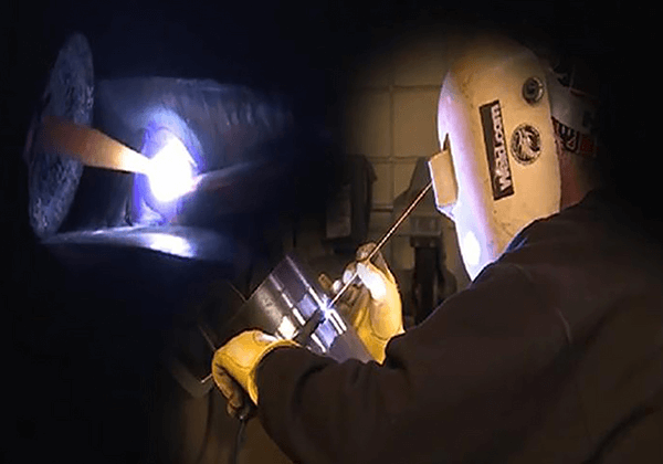
With the development of science and technology, welding has become more important in industrial production. From the analysis of a large number of structural accidents, it can be seen that many of them are caused by poor welding quality, and the sense of responsibility and operational skills of welders directly affect the welding quality.
In order to improve the quality of welders and ensure the safety and reliability of welded structures, it is necessary to provide training and assessment for welders.
Section 1: Welding Defects
Welding Defects: Defects in welding joints that do not meet the requirements of design or process documents.
1. Classification of Welding Defects:
According to the location of welding defects in the weld, they can be divided into two categories: external defects and internal defects. External defects are located on the outer surface of the weld and can be observed with the naked eye or a low-powered magnifying glass.
Examples include improper weld size, undercut, weld bead, arc pit, burn-through, sagging, surface porosity, surface cracks, etc. Internal defects are located inside the weld and require destructive testing or non-destructive testing methods to detect. Examples include incomplete penetration, lack of fusion, slag inclusion, internal porosity, internal cracks, etc.
2. Common Electric Welding Defects:
(1) Improper weld size:
Refers to uneven width, height, inadequate or excessive weld size. A weld size that is too small will reduce the strength of the welded joint, while a size that is too large will increase stress and deformation in the structure, leading to stress concentration and increased welding workload.
Improper weld preparation angle or uneven assembly clearance, excessive or insufficient welding current, incorrect travel speed or angle can all result in weld size noncompliance.
(2) Undercut:
It refers to the groove or depression formed along the toe of the weld due to improper welding parameters or incorrect operating procedures.
Undercut reduces the effective cross-sectional area of the base metal, weakens the strength of the welded joint, and can cause stress concentration and crack formation at the undercut, even leading to structural failure. Undercut exceeding the allowable value should be repaired by additional welding.
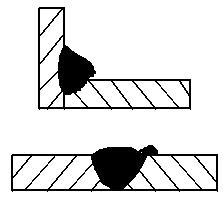
(3) Weld bead:
It refers to the metal bead formed on the unmelted base metal outside the weld during the welding process. Weld bead not only affects the appearance of the weld but also frequently hides incomplete fusion defects underneath, leading to stress concentration.
In the case of pipe joints, weld beads inside the pipe can reduce the effective area and even cause blockage.
Weld beads often occur in flat welding and horizontal welding. Excessive gap between welds, incorrect electrode angle and travel method, poor electrode quality, excessive welding current, or too slow welding speed can all cause weld bead formation.
(4) Burn-through:
It refers to the defect where molten metal flows out from the back of the groove during the welding process, forming a hole. Burn-through often occurs during root pass welding. Burn-through makes it difficult to continue the welding process and is an unacceptable welding defect.
The main causes of burn-through are excessive welding current or too low welding speed, excessive groove and gap, or inadequate edge preparation.
To prevent burn-through, proper design of groove dimensions, ensuring assembly quality, and selecting appropriate welding process parameters are necessary. For single-sided welding, methods such as using copper backing plates or flux can be employed to prevent burn-through. When manual arc welding thin plates, skip welding or intermittent arc welding techniques can be used.
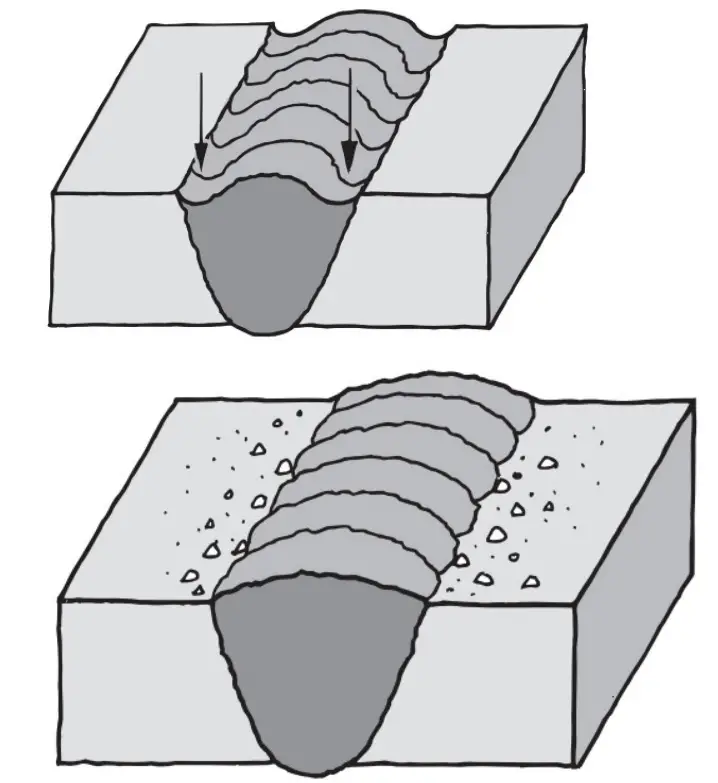
(5) Incomplete penetration:
It refers to the phenomenon where the root of the joint is not completely melted during welding. Incomplete penetration often occurs in the root of single-sided welding and the middle of double-sided welding.
Incomplete penetration not only reduces the mechanical properties of the welded joint but also creates stress concentration points at the incomplete penetration, leading to crack formation.
The causes of incomplete penetration include insufficient welding current, excessive welding speed, improper electrode angle, arc blow, insufficient groove angle or gap, rapid heat dissipation of the workpiece, hindrance of oxidation and slag, etc.
Any factor that prevents sufficient fusion between the electrode metal and the base metal can cause incomplete penetration.
Measures to prevent incomplete penetration include:
① Proper selection of groove form and assembly clearance, and removal of dirt and slag between the groove sides and weld layers.
② Selection of appropriate welding current and speed.
③ During travel, constant attention should be paid to adjusting the electrode angle, especially when encountering arc blow or electrode eccentricity, to ensure sufficient fusion between the weld metal and the base metal.
④ For workpieces with high heat conductivity and large heat dissipation area, preheating before welding or heating during the welding process should be applied.
(6) Lack of fusion:
Lack of fusion refers to the portion where the weld metal and the base metal or between weld metals are not fully melted and fused during welding. Lack of fusion has similar hazards to incomplete penetration. The causes of lack of fusion include low welding heat input, arc blow, rust and dirt on the groove sidewalls, incomplete slag removal between weld layers, etc.
(7) Craters, sinking, and lack of weld metal:
Craters refer to the local depressions formed on the surface or back of the weld, lower than the surface of the base metal. Sinking occurs when excessive molten metal penetrates through the back of the weld, causing the front of the weld to sink and the back to protrude. Lack of weld metal refers to the continuous or intermittent groove formed on the surface of the weld due to insufficient filler metal.
These defects weaken the effective cross-sectional area of the weld, leading to stress concentration and a severe reduction in weld strength. Sinking often occurs in flat welding and horizontal welding, especially in pipe welding, where such defects are likely to occur due to molten metal sagging. In argon arc welding, attention should be paid to making the electrode stay at the molten pool for a short time during arc termination or using circular travel to avoid craters at the arc termination.
(8) Tungsten inclusion:
Causes:
⑴ Improper welding operation causes the tungsten electrode to contact the workpiece and melt into the weld metal.
⑵ Using a small-diameter tungsten electrode with a high welding current.
⑶ The filler wire touches the tip of the tungsten electrode.
⑷ Excessive burning and overheating of the tungsten electrode.
⑸ Poor gas protection or severe oxidation of the tungsten electrode.
Preventive measures:
⑴ Use high-frequency high-voltage arc ignition to prevent contact arc ignition.
⑵ Select the appropriate tungsten electrode diameter according to the required welding current. ⑶ Strengthen operational skills training and avoid contact between the filler wire and the tungsten electrode.
⑷ Immediately grind and replace the tungsten electrode if it has severe cracks or burns.
⑸ Ensure the appropriate protrusion length of the tungsten electrode, increase gas flow rate, and increase post-flow time to prevent tungsten oxidation.
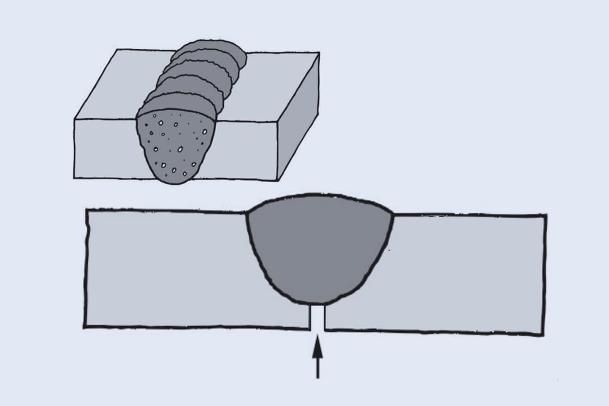
(9) Porosity:
① Formation and hazards of porosity:
During welding, bubbles in the molten pool that fail to escape during solidification and remain behind form voids called porosity. Porosity can be classified as dense porosity and pinhole porosity. The main gas that forms porosity in the weld is hydrogen. Hydrogen in the welding area can come from various sources, including moisture in the arc column atmosphere, moisture adsorbed on the welding material and base metal surface oxide film.
These moisture sources form bubbles in the molten pool under the high temperature of the arc but fail to rise and form porosity. Porosity has a significant impact on the performance of the weld. It not only reduces the effective working cross-section of the weld and weakens its mechanical properties but also compromises the density of the weld, making it prone to leakage. The edges of porosity can cause stress concentration, reducing the weld’s plasticity.
Therefore, strict control of porosity is essential for critical weldments.
② Causes of Porosity:
① Low purity of argon gas, excessive impurities, or moisture in the argon gas pipeline, and gas leakage in the pipeline.
② Inadequate cleaning of the welding wire or base metal near the groove before welding, or recontamination with dirt and moisture after cleaning.
③ Poor argon gas protection during argon arc welding, unstable arc, excessively long arc length, excessive tungsten electrode protrusion.
④ Improper selection of welding parameters, too fast or too slow welding speed.
⑤ High humidity in the surrounding environment and high wind speed.
② Clean the welding wire and base metal near the groove properly.
③ Choose the correct welding parameters.
④ Preheating before welding if necessary.
⑤ Avoid working in a humid environment and implement wind protection measures.
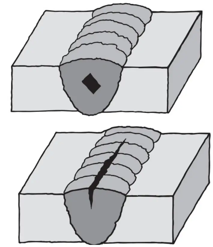
(10) Cracks:
Cracks are gaps formed by the destruction of the atomic bonding force in localized areas of the metal in the welded joint under welding stresses and other embrittlement factors. Cracks in welded joints, especially thermal cracks in aluminum and aluminum alloy welding, are the most dangerous welding defects.
They have a severe impact on the performance, usability, and safety of welded structures and are the main cause of many welding structural failures.
Causes of cracks:
① Improper selection of welding wire: When the Mg content in the weld is less than 3% or when the Fe and Si impurity content exceeds the specified limit, the crack tendency increases. When the welding temperature is too high, liquation cracks occur in the heat-affected zone.
② Improper selection of welding sequence.
③ If the heat source is removed too quickly during welding termination or interruption, or if the crater is not filled properly, crater cracks are likely to occur.
④ Concentration of welds or excessive heat in the heat-affected zone results in excessive deformation stress.
⑤ Excessive impurities in solvents and welding wire shielding gas.
⑥ Unreasonable structural design with excessive concentration of welds, leading to excessive restrained stress in the welded joint.
Preventive measures:
① Proper selection of welding wire to ensure good matching of weld composition and base metal composition.
② Selecting a reasonable welding sequence.
③ When welding is terminated or interrupted, reduce the arc current, extend the arc termination time slightly, and fill the arc termination area with filler wire, or install a crater filling device at the end of the weld to terminate the arc.
④ Controlling the temperature and deformation in the heat-affected zone, and implementing preheating measures if necessary.
⑤ Reduce the rigidity of the welding structure, and avoid stress concentration as much as possible in the weld.
Section 2: Welding Defect Inspection
The Importance of Welding Inspection:
Welding inspection is an important measure to ensure excellent product quality and prevent scrap from leaving the factory. During the trial production process, inspection can identify quality issues, identify the causes, and eliminate defects. This ensures the application of new products or processes and guarantees quality.
1. Non-destructive Testing
Non-destructive testing refers to the method of detecting defects without damaging the tested material or finished product’s performance and integrity. It includes visual inspection, tightness inspection, and non-destructive testing.
1.1 Visual Inspection
Visual inspection of welded joints is a simple and widely used method. It is generally performed with the naked eye or using a 5-10x magnifying glass. The main purpose is to check for defects such as cracks, porosity, undercut, weld bead, burn-through, and craters on the surface of the weld.
It also examines the quality of weld formation, whether the reinforcement height meets the pattern requirements, and the smooth transition of the weld to the base metal.
2. Tightness Inspection
This inspection method is mainly used to detect the penetrability defects in vessels or pipelines that are not under high pressure or low pressure. Common tightness inspection methods include hydrostatic testing and pneumatic testing.
2.1 Hydrostatic Testing
Hydrostatic testing is commonly used to check the strength and tightness of the shell and welds. The specific procedure is as follows:
① Select a qualified pressure gauge with an accuracy of no less than 1.5 grade.
② Fill the vessel with water, ensuring all air inside the vessel is thoroughly removed, and seal all openings and ports on the vessel. Then, use a water pump to increase the pressure inside the vessel to 1.25 to 1.5 times the working pressure.
③ During the pressurization process, the pressure should be increased gradually and temporarily held at each level. It should not be raised to the test pressure in one step. Maintain the pressure for a certain period of time. Afterward, slowly reduce the pressure back to the working pressure and carefully inspect the welds.
If water droplets, fine streams of water, or signs of dampness are found on the weld, it indicates that the weld is not tight. Mark it and carry out repair work after unloading the vessel until the hydrostatic test is qualified.
④ Hydrostatic testing can also be performed as a destructive test to evaluate the load-bearing capacity of the product.
2.2 Pneumatic Testing
Pneumatic testing is a more sensitive and rapid method compared to hydrostatic testing, and the tested product does not require drainage afterward.
However, pneumatic testing carries higher risks than hydrostatic testing. During the test, the air pressure is first pressurized to the specified value according to the technical conditions of the product. Then, the intake valve is closed, and the pressurization is stopped.
A measuring device is used to move around the weld to check for air leakage (or a soap solution can be applied) or to observe whether there is a decrease in the reading on the pressure gauge. If the measuring device triggers an alarm, it indicates that the welded joint is not tight. After pressure is released, repair and re-welding should be carried out until another inspection confirms its qualification before leaving the factory.
3. Non-destructive Testing
Non-destructive testing is mainly used to detect fine surface defects and internal defects in the weld. Examples include slag inclusions, porosity, cracks, lack of fusion, etc. These testing methods have been widely applied in important welded structures. Common non-destructive testing methods include dye penetrant testing, ultrasonic testing, and radiographic testing.
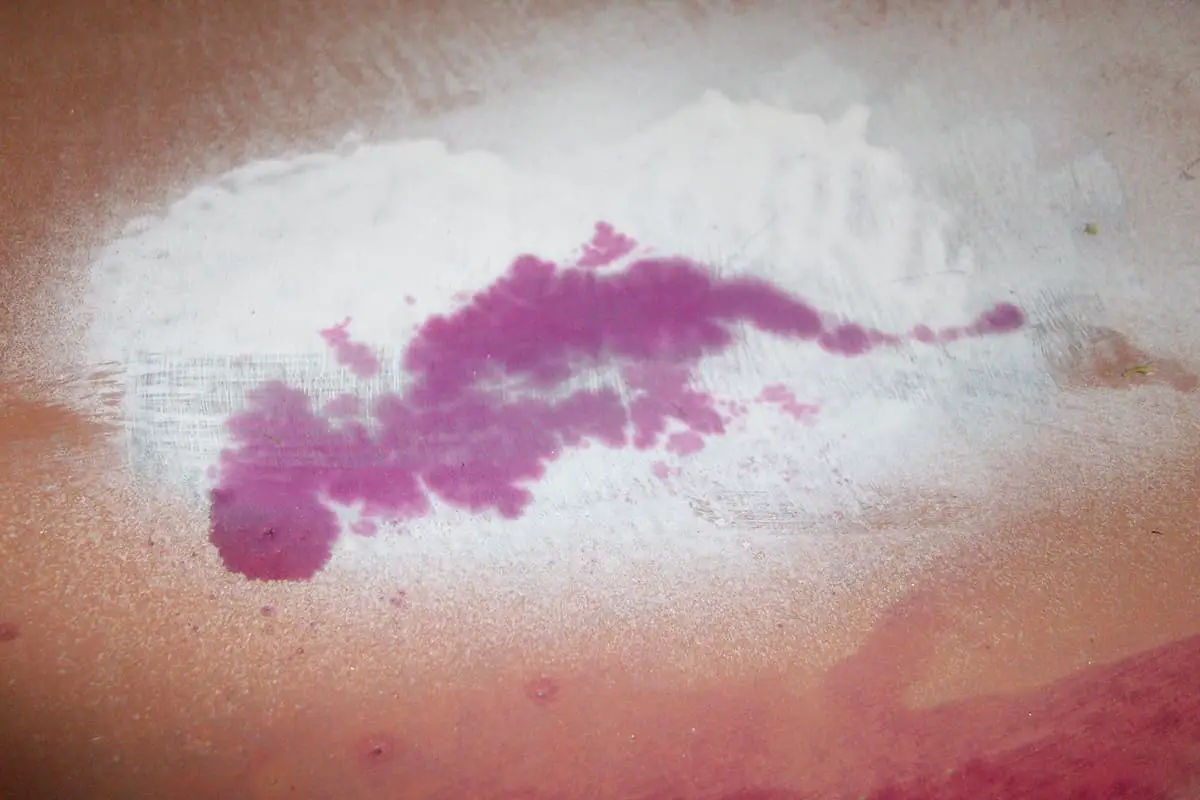
3.1 Dye Penetrant Testing
Dye penetrant testing is a method used to detect surface defects in weldments. However, it requires a high surface finish of the weldment. During the inspection, the weldment is cleaned with a cleaning agent and then sprayed with a dye penetrant. The dye penetrant with good fluidity and permeability infiltrates into the fine cracks on the surface of the weld.
Afterward, the weldment surface is cleaned with a cleaning agent and coated with a developer. When the dye penetrant that has infiltrated into the crack encounters the developer, the position, shape, and size of the defect will be revealed.
3.2 Ultrasonic Testing
Ultrasonic testing is used to detect internal defects in thick welded joints. It is suitable for detecting defects such as porosity, inclusions, and cracks in any part of a weld with a thickness ranging from 8 to 120mm. However, ultrasonic testing has limited capability in distinguishing defects and lacks visual representation.
During the inspection, the workpiece surface should be smooth and coated with a layer of oil as a medium. Ultrasonic waves are transmitted into the workpiece from the surface and propagate internally. When they encounter internal defects, the workpiece surface, or the bottom surface, they will cause reflections.
The ultrasonic waves are converted into electrical signals by the probe. The distance between the defect pulse and the initial pulse and bottom pulse determines the depth of the defect, while the height of the defect pulse signal determines the size of the defect.
3.3 Radiographic Testing
Radiographic testing is an accurate and reliable method for detecting internal defects in welds. X-rays are commonly used for radiographic testing. It is suitable for detecting defects such as porosity, inclusions, lack of penetration, lack of fusion, and cracks within welds with a thickness of 2 to 65mm.
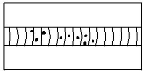
X-rays can visually and accurately reflect the location, shape, size, and distribution of defects. Lack of penetration appears as a discontinuous or continuous black line on the film, often offset from the center of the weld, with varying widths and uneven blackness.
Porosity is characterized by inconsistent distribution, with dense and sparse circular or elliptical black dots. The blackness of porosity is generally larger and more uniform near the center, gradually decreasing towards the edges. Slag inclusions often appear as different shapes, either as dots or elongated shapes on the film.
Dot-shaped slag inclusions are individual black dots with irregular shapes and angular edges, with relatively uniform blackness. Elongated slag inclusions appear as wide and short thick lines, with inconsistent widths.
Cracks generally appear as slightly curved black fine lines on the film, sometimes appearing as straight fine lines. They have distinct outlines, with tapering ends and a slightly wider middle section.
Branching phenomena are rarely seen, and the blackness gradually decreases towards the ends until it disappears. In radiographic testing standards, weld quality is divided into four grades, with Grade I representing the best quality and Grade IV representing the worst quality. Radiographic testing can directly determine the type of defect from the film, while it is more challenging to determine the defect type using ultrasonic testing.
3.4. Destructive Testing of Mechanical Properties:
This includes tension testing, bending testing (positive, negative, and through thickness), hardness testing, impact testing, and metallographic testing (macro and micro).
⑴ Tension testing can determine the tensile strength, yield strength, and plasticity (elongation and reduction of area) of welded joints, as well as defects at the weld fracture.
⑵ Bending testing: evaluates the plasticity of welded joints.
⑶ Impact testing: assesses the impact toughness and notch sensitivity of weld metal and welded joints.
⑷ Hardness testing: examines the hardness of welds and heat-affected zones, allowing for indirect estimation of material strength.
⑸ Metallographic testing: primarily observes changes in metallographic structure and microdefects resulting from metallurgical processes.
Section 3: Rework of Welding Defects
After welding quality inspection, if defects exceeding the allowable standards are found, rework should be performed. Strict welding quality control and inspection of welding process conditions are generally carried out by skilled technicians, and welding defects only occur under extremely rare conditions.
1. Determination of Welding Defects
Before rework of welding defects, it is crucial to accurately determine the type, location, and size of the defects. This is essential to ensure that the rework is qualified on the first attempt.
For internal defects, comprehensive non-destructive testing methods such as radiographic and ultrasonic testing should be used to accurately determine the type, location, and size of the welding defects.
2. Development of Rework Plan for Welding Defects
For pressure vessel welding defects, a rework plan should be developed prior to the rework process. The rework plan should also be approved by a welding engineer. The implementation of the rework plan should be based on the evaluation of welding procedures, and only if it is deemed qualified should the rework be carried out.
The rework plan should focus on ensuring that the rework is qualified on the first attempt. The number of rework attempts in the same area of the weld should not exceed two.
3. Removal of Welding Defects
Mechanical methods should be used to remove welding defects instead of arc methods. Mechanical removal can be achieved using angle grinding wheels, turning, or pneumatic milling cutters. The removal process will not heat the welding joint, thereby avoiding any changes in the structure and properties of the joint.
Pay attention to the creation of grooves, slots, and the appropriate groove width and length during defect removal, taking into account the stress and deformation during the re-welding process.
4. Re-Welding
After removing welding defects, oil stains and oxide films should be cleaned. Re-welding should be carried out according to the approved welding procedure specification. During re-welding, it is advisable to use a lower welding energy and apply appropriate preheating measures.
Multi-layer welding should be performed whenever possible. Post-welding measures should be taken to prevent the occurrence of welding defects.
Section 4: Inspection Standards for Weld Seam Appearance
1. Inspection of Weld Seam Appearance Dimension
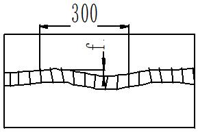
1. Weld seam length within range of 300mm, weld seam unevenness ≤ 1mm.
2. Weld seam length within range of 300mm, weld seam width difference ≤ 1mm.
3. Weld seam length within range of 300mm, weld seam edge straightness ≤ 2.0mm.
4. Weld seam surface ripple should be uniform and consistent, with ripple spacing of 2-3mm and height difference between ripples ≤ 0.5mm.
5.1 For base material thickness of 6≤δ<16mm, outer weld seam width of cylindrical body: 16±1mm, excess height: 0.5-2mm; after grinding, inner weld seam excess height: 0.5-1mm and smooth transition with base material.
5.2 For base material thickness of 16≤δ≤20mm, outer weld seam width of cylindrical body: 20±1mm, excess height: 0.5-2mm; after grinding, inner weld seam excess height: 0.5-1mm and smooth transition with base material.
5.3 For cylinder diameter larger than 320mm, automatic GTAW cover must be used for longitudinal butt welds.
6. The requirements for misalignment of butt welds are shown in Table 1:
Table 1
Plate thickness δ(mm)
Misalignment tolerance e(mm)
Longitudinal butt weld
6>δ
e≤1
6≤δ<16
e≤1.5
16≤δ
e≤2
Circumferential butt weld
6>δ
e≤1
6≤δ<16
e≤1.5
16≤δ
e≤2.5
7. Bulging at circumferential weld seam ≤ 1mm.
8. Appearance and inspection requirements for fillet welds:
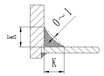
8.1 Weld fillet dimension: Shall be executed according to the drawing or process requirements, with a tolerance of (0~+1).
8.2 After automatic GMAW welding of fillet welds, automatic GTAW re-melting is required.
8.3 If not specified on the drawing, follow the requirements as specified below:
(a) For wall thickness t of the cylinder: 6~10.5mm; height of fillet welds inside and outside the cylinder: GMAW: 8+1mm, GTAW: 10+1mm.
(b) For wall thickness t of the cylinder: 12mm; height of fillet welds inside and outside the cylinder: GMAW: 10+1mm, GTAW: 12+1mm.
(c) For wall thickness t of the cylinder: 15~16mm; height of fillet welds inside and outside the cylinder: GMAW: 12+1mm, GTAW: 14+1mm.
(d) The inner weld seam is a flat weld seam, which should have a smooth transition with the base material and should not be lower than the base material surface.
(e) The outer weld seam is a flat weld seam, with the width of the weld seam meeting the requirements of sections 5.1 and 5.2, and the excess height of the weld seam being 0.5~2mm.
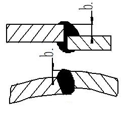
9. The height difference between weld fillet dimensions (a-b) ≤ 2mm (see Figure 1); excluding the influence of welds on bolt assembly as specified on the drawing or process.
Fig. 1
10. Weld seam depression 0-1mm. (see Figure 2)
Fig. 2
2. Welding Defect Inspection and Remedial Measures
1. Weld Seam Undercut:
The depth of the weld seam undercut should not exceed 0.3 mm, and the total length of the undercut on both sides of the weld seam should not exceed 10% of the length of the weld seam.
1.1 If the depth of the weld seam undercut is greater than 0.3 mm but not more than 0.5 mm, the undercut on the parent material at the weld seam should be ground using an electric or pneumatic grinding disc to achieve a smooth transition between the weld seam and the parent material, without leaving any depressions after grinding.
1.2 If the depth of the weld seam undercut is greater than 0.5 mm, manual TIG welding should be performed to fill the undercut defect. After welding, the area should be ground using an electric or pneumatic grinding disc to achieve a smooth transition, without leaving any depressions on the weld seam after grinding.
2. Porosity:
No porosity is allowed on the surface of the weld seam.
2.1 For porosity smaller than Φ0.5 mm, the defect should be tapped with a small hammer and then ground away using an electric or pneumatic grinding disc.
2.2 For porosity larger than Φ0.5 mm or clustered porosity, after removing the porosity defect, manual TIG welding should be performed, followed by grinding with an electric or pneumatic grinding disc to achieve a smooth finish.
3. Weld Spatter:
No weld spatter is allowed on the surface of the weld seam.
3.1 Weld spatter should be repaired using manual TIG welding or ground away using an angle grinder to achieve a smooth finish.
4. Cracks:
No cracks are allowed on the weld seam.
4.1 If cracks are found, the crack defect should be completely removed, followed by manual TIG welding.
5. Burn-through, incomplete fusion, incomplete penetration, and depressions are not allowed.
5.1 If incomplete fusion, incomplete penetration, or depressions are found, they must be repaired using manual TIG welding.
6. The inner and outer surfaces of the shell should be free from weld spatter, weld beads, oxides, etc.
6.1 If weld spatter, weld beads, or oxides are found on the weld seam, they should be completely removed using a stainless steel wire brush or grinding disc.
7. Weld Seam Overlap:
In straight seam and circumferential seam welding of the shell, the overlapped portion of the weld seam should not have a height difference of more than 0.5 mm. At the joint of the weld seam, the weld seam should not have a height difference of more than 0.5 mm.
8. Each weld seam should not be repaired in more than one location, and after repair, there should be no undercut, porosity, cracks, or depressions as welding defects.
9. If the appearance of the outer weld seam joint is unsightly, it should be ground using an angle grinder, with the grinding length not exceeding 30 mm. (No grinding is allowed in other areas).
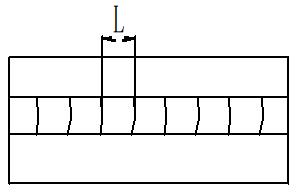
10. If the width of the weld seam at the repair area exceeds the original weld seam width, it should be ground to be level and consistent with the original weld seam width, with a smooth transition. (See Figure 3)
Fig. 3
11. Weld Seam Inspection Diagram
Weld Seam Inspection Diagram
NO.
Diagram of Defect Types
Weld Seam Requirements and Measures
1
Straightness
Maximum allowable deviation of f > 2mm within any 300m
2
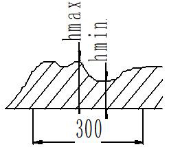
Unevenness Difference
Maximum allowable difference of (hmax – hmin) > 1mm within any 300mm
3
Misalignment
Perform inspection of weld seam outer appearance dimensions according to item 6.
4
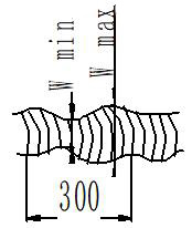
Thickness Variation
Maximum allowable difference of (wmax – wmin) > 1mm within any 30mm
5
Wavelength of corrugations
Wavelength of corrugations: L = 2~3mm
6
Undercut
Execute inspection of undercut depth (h) according to item 1 of weld seam defect inspection.
7
Defects or repairs are not allowed to be removed or welded.
8
Defects and repairs are not allowed to exist or be removed or welded.
9
Weld Seam Bulge
Grinding or welding repairs are not allowed.
10
Incomplete filling or depressions
The presence of weld repairs is not allowed.
11
Incomplete penetration
Weld repairs are not allowed.
12
Weld spatter and oxides
Cleaning is not permitted.
3. Weld Seam Inspection Tools:
Bright light source, magnifying glass up to 5x magnification, weld seam inspection ruler.
As the founder of MachineMFG, I have dedicated over a decade of my career to the metalworking industry. My extensive experience has allowed me to become an expert in the fields of sheet metal fabrication, machining, mechanical engineering, and machine tools for metals. I am constantly thinking, reading, and writing about these subjects, constantly striving to stay at the forefront of my field. Let my knowledge and expertise be an asset to your business.
Achieving a flawless weld requires more than just skill; it hinges on mastering the interplay between voltage and current. These two parameters are the lifeblood of welding, dictating everything from…
Have you ever wondered why welded structures sometimes fail despite their robust appearance? This article dives into the hidden challenges of welding, exploring how uneven heating and cooling can lead…
Ever wondered how skyscrapers stand tall or cars stay welded together? This blog uncovers the magic behind electric welding machines. Learn about top manufacturers like Lincoln Electric and Miller Welds,…
Ever wondered how welders achieve perfect joints in challenging positions? 6GR welding is a specialized technique for welding pipelines with an obstacle ring at a 45° angle, crucial for ensuring…
Have you ever wondered about the hidden dangers behind the bright sparks of welding? In this article, we explore the harmful effects of argon arc welding on the human body.…
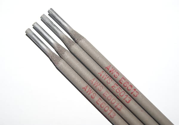
Ever wondered what those numbers and letters on welding rods mean? This article demystifies the coding system for carbon and stainless steel welding rods, helping you understand their tensile strength,…
Have you ever wondered how to calculate the consumption of welding rods accurately? In this blog post, we'll explore the methods and formulas used by industry experts to estimate welding…
Have you ever wondered how to effectively weld different types of stainless steel? This article dives into the specialized welding methods for martensitic and duplex stainless steel, detailing the challenges…
Welding stainless steel demands precision to prevent defects like cracking and corrosion. Are you aware of the critical steps to ensure a flawless weld? This article highlights eight essential precautions,…