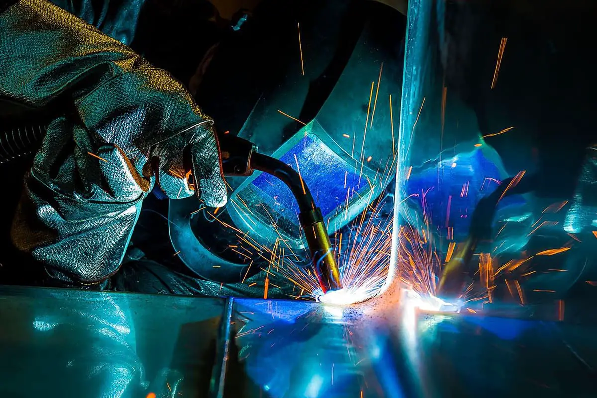
1. Introduction Our company along with other companies frequently undertake welding and fabrication tasks involving titanium alloy and other non-ferrous metals. Initially, in order to successfully complete production tasks, I searched for information, consulted experts and experienced welders, and learned through a combination of study and practice. Eventually, we successfully fulfilled orders for titanium alloy […]
Our company along with other companies frequently undertake welding and fabrication tasks involving titanium alloy and other non-ferrous metals. Initially, in order to successfully complete production tasks, I searched for information, consulted experts and experienced welders, and learned through a combination of study and practice.
Eventually, we successfully fulfilled orders for titanium alloy welding and fabrication.
Subsequently, I participated in multiple titanium alloy welding projects, continuously learning and gaining a deeper understanding of titanium alloy welding. I have also summarized some experiences that can be used as a reference for future titanium alloy welding.

The commonly used welding methods for titanium and titanium alloys include argon arc welding, submerged arc welding, and vacuum electron beam welding, among which tungsten inert gas (TIG) welding is the most widely used. Therefore, we chose TIG welding.
When selecting welding wire, it is necessary to ensure that the content of harmful impurities is as low as possible, while also meeting the requirements for the plasticity and strength of the weld.
Generally, the principle is to use welding wire with the same composition as the base material. In our actual welding, we used TA4 titanium alloy welding wire that had a composition similar to the base material.
Later, in order to save materials, we cut the scraps of the base material into narrow strips and used them as welding wire, which also yielded good results.
Titanium alloy welding is prone to the formation of hydrogen pores and sometimes carbon monoxide pores. To prevent porosity, it is necessary to strictly control the content of impurities such as hydrogen, oxygen, and carbon in the raw materials.
We conducted physical and chemical tests on both the base material and the welding wire, and the welding wire we used was also subjected to vacuum annealing treatment to ensure that the content of hydrogen and oxygen did not exceed the specified limits.
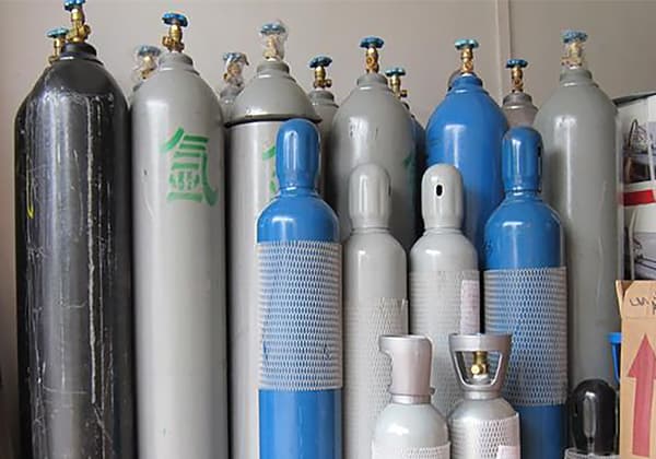
When the thickness of the titanium alloy sheet is less than 3.2mm, pure argon gas is used for shielding. Since the batch of orders we received mainly consisted of thin sheets with a thickness of 2mm, we used pure argon gas for shielding, with a purity requirement of ≥99.99%.
The oxygen content should be lower than 0.002%, nitrogen content lower than 0.005%, hydrogen content lower than 0.002%, moisture content below 0.001mg/L, and relative humidity ≤5%.
Additionally, for sheet thicknesses greater than 3.2mm, argon-helium shielding gas can be used to increase penetration depth, improve arc heat power, and increase welding productivity. The argon-helium ratio is 25% argon and 75% helium.
Firstly, mechanical cleaning is performed to remove dirt and oxide scale from the welding area using cutting, sandblasting, shot blasting, or wire brushing.
Secondly, chemical cleaning is carried out by using solvents such as alcohol, acetone, and carbon tetrachloride to remove oil, dust, and other contaminants from the surface of the weldment and welding wire.
Then, a pickling process using HNO3 mixed with HF (10:1) is conducted to remove oxides until a silver-white metallic luster is achieved.
After pickling, thorough rinsing with running water is done, followed by wiping the surface of the welding wire and welding area of the weldment with acetone or alcohol before welding.
Finally, scraping is performed in areas where acid pickling is not possible, using a hard alloy scraper to remove approximately 0.025mm of the metal surface within a range of 15-20mm from the groove and the edge of the joint.
Although titanium and titanium alloys have low sulfur and phosphorus impurities, they can still develop stress cracks and cold cracks when not properly protected.
Moreover, titanium is easily oxidized at high temperatures during welding. If the weld metal and the high-temperature near-weld zone, whether on the front or back side, are not effectively protected, they are prone to contamination by impurities such as air, resulting in greater embrittlement.
Experimental evidence has shown that strengthening gas protection in the welding area can improve the weld structure and prevent crack formation. We used the following methods for protection:
Firstly, a rotating local protection device was made. We created a local protection device with a “curtain” size of 15mm×20mm, which rotates relative to the workpiece during welding. The gap between the workpiece and the rotating surface of the “curtain” should be as small as possible, generally ≤0.5mm.
Secondly, the use of a shielding hood. We made a shielding hood with a thickness of about 1mm using pure copper plates. The hood has a width of 20-40mm and a length of 80-120mm. The principle is that the gas flow enters through the inlet pipe and is distributed evenly by a row of small holes or slots in the distribution tube before being blown upwards.
The outer shell of the hood reflects the gas flow downwards, and after passing through several layers of fine copper wire mesh, it is uniformly distributed onto the weldment. The main requirement for the hood is that the protective gas flowing out should be evenly distributed in a laminar flow rather than turbulent flow. The inner transition of the hood should be smooth, with minimal dead corners. During welding, the hood is positioned against the back side of the welding area and moves along with the welding torch.
Lastly, backside protection. During welding, the temperature on the back side of the weld bead also exceeds 400°C, so it also requires protection. Therefore, we made a copper backing plate that can deliver protective gas. The backing plate is placed on the back side of the weld bead to isolate it from the air and accelerate cooling in the welding area.
When the structure of the workpiece is complex and it is difficult to implement shielding hoods or backside protection, the method of welding in a box with vacuum evacuation and filling with argon gas can be used. This ensures that the workpiece is welded in an inert atmosphere with overall gas protection.

Tungsten inert gas (TIG) welding of titanium does not have any special requirements for the welding power source.
Generally, a direct current welding machine with a steep drop external characteristic can meet the requirements. We used direct current straight polarity TIG welding for welding.
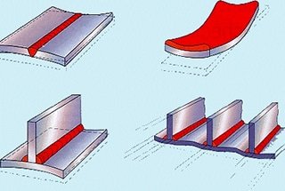
Due to the lower elastic modulus of titanium compared to steel, the deformation during welding titanium is approximately twice as large under the same applied stress.
Therefore, during welding, we used titanium plates and clamps to tightly secure the workpiece to prevent and reduce welding deformation.
This also reduces the residence time of the metal in the high-temperature zone and the width of the overheated zone, improving the quality of the joint.
Since we were welding thin sheets and the possibility of cracking was relatively low, and considering the deformation issue, we did not take preheating measures. However, for welding thick plates, rapid cooling can easily lead to cold cracks.
Therefore, it is necessary to reduce the heat input during welding and also preheat appropriately before welding to slow down the cooling rate after welding, preventing the formation of unstable microstructures in the joint and avoiding embrittlement. The preheating temperature is generally around 200°C.
Consistent welding spacing is achieved by using fixtures and adjusting shims to avoid misalignment. It is important not to position welds at intersections or areas of high stress concentration. Any black oxide film or other defects (such as porosity or cracks) generated during the positioning welds should be promptly removed.

The welding current should be set to ensure that it is not overheating and prevent the formation of hardened structures. It is preferable to use a lower heat input to avoid grain coarsening and improve the ductility of the weld joint. Additionally, a lower welding heat input reduces the time the molten pool stays in the liquid state and helps reduce porosity. For welding 2mm thick titanium alloy using TIG welding with direct current straight polarity, the welding current is set between 80-100A.
Arc voltage primarily affects the width of the weld bead and is determined by the arc length. Increasing the arc length can decrease the effectiveness of gas protection. Generally, the arc length should be controlled to be between 1-5mm. The shape and size of the tungsten electrode, as well as the diameter and feed rate of the filler wire, should be adjusted accordingly.
Cerium tungsten electrodes are commonly used for welding titanium alloys. Cerium tungsten electrodes have a fine and concentrated arc, which improves the current density by 5-8%, reduces burn-off rate, and has a longer lifespan.
When using direct current, the cathode voltage is reduced by 10%, making it easier to initiate an arc. Cerium tungsten electrodes are also non-radioactive. The shape and size of the tungsten electrode affect the stability of the arc.
The tip of the electrode should be sharpened before use, and the degree of sharpening depends on the diameter of the filler wire and the welding current. For welding thin plates and using low welding currents, a smaller diameter tungsten electrode with a sharper tip is preferred for easy ignition and stability.
For welding 2mm thick titanium alloy, a tungsten electrode with a diameter of 1.6mm, a tip diameter of 0.8mm, and a cone angle of 35° is used. The tip of the tungsten electrode should be properly shaped using a hard grinding wheel and then cleaned.
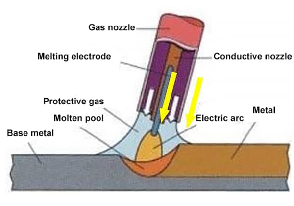
The welding gun and nozzle used for titanium alloy welding differ from those used for welding aluminum or stainless steel. Larger diameter main nozzles are often used to protect the weld pool.
The gas flow rate and nozzle diameter should be adjusted to achieve optimal performance. If there is excessive spatter on the nozzle, it should be cleaned or replaced in a timely manner. The gas flow rate is primarily determined by the nozzle diameter and is also influenced by the welding current.
The gas flow rate is usually 0.8-1.2 times the nozzle diameter. In this case, with a nozzle diameter of 10mm, the gas flow rate is set at 8-12L/min.
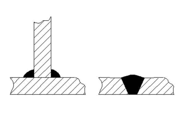
The extension length of the tungsten electrode is generally 1-2 times its diameter and is also influenced by the shape of the weld joint. For fillet welds, a slightly longer extension length (3-4mm) is used so that the tungsten electrode reaches the root of the joint and allows for better visibility of the weld pool. For butt welds, the tungsten electrode extension length is slightly shorter (2-3mm) to achieve optimal protection.
After determining the welding current, the welding speed determines the amount of energy input per unit length of the weld bead, or the welding heat input. Increasing the welding speed reduces the depth and width of the fusion zone, while decreasing the speed increases them.
Therefore, to maintain a certain weld shape factor, the welding current and speed should be adjusted simultaneously. For a welding current of 80-100A, the welding speed is set at 150-200mm/min.
There are two types of welding guns: air-cooled and water-cooled. Air-cooled guns are used for low currents (generally less than 150A) and rely on the flow of protective gas for cooling. In this case, an air-cooled gun is used.

This involves checking if the equipment’s water, gas, and electrical circuits are functioning correctly, if the assembly quality of the workpiece meets the requirements, if pre-weld cleaning has been properly done, if the tungsten electrode has been prepared, and if the welding parameters have been appropriately adjusted.
After pressing the start button on the welding gun, the welding machine starts working. The gas flow is initiated first, followed by arc initiation. During arc initiation, attention should be paid to controlling the distance between the tungsten electrode and the workpiece to avoid tungsten inclusion.
The most reliable method is to tilt the welding gun, allowing the nozzle to make contact with the workpiece surface and gradually bring the electrode closer until the arc strikes.
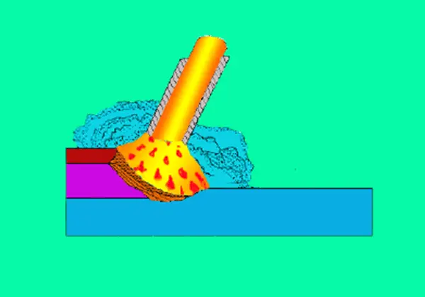
For flat welding, the torch is usually angled at 70°-75° to the horizontal plane, while the filler wire is at an angle of 20°.
In lap welding, the torch is inclined at 20° toward the lap joint, while the other directions remain unchanged. For vertical welding, the torch is moved from bottom to top, with the torch axis maintained nearly perpendicular to the filler wire. The filler wire is fed from above at an angle of 15° to the workpiece plane.
The filler wire should be slowly fed into the leading edge of the molten pool after it has formed, rather than directly into the center of the pool.
Fine wire can be continuously fed, while thicker wire should be intermittently fed with a slight back-and-forth motion. However, the wire should not leave the argon gas protection area to prevent oxidation of the hot wire.
The filler wire should not touch the tungsten electrode and should not disturb the flow of argon gas. Using excessively thick filler wire or feeding the wire too quickly can result in large droplets entering the pool, causing a sudden drop in the weld pool temperature and increased viscosity of the molten metal, which adversely affects penetration and bead formation.
First, double-sided formation:
When performing backside welding, the welder can observe the state of the weld pool to determine if it has penetrated through the joint. In a normal state, the molten pool metal rotates. If the gas protection is inadequate or the welding current is too low, there will be no rotation.
When the filler metal droplets are added to the molten pool, the surface of the pool will rise, and as the arc heat is transferred downward, the base metal will be melted. When complete penetration is achieved, gravity causes the molten pool to sink, resulting in a decrease in the surface level and an expansion of the area. If there is no sinking, it indicates incomplete penetration.
If there is excessive sinking or a depression, it indicates that there has been a weld-through on the backside.
Second, oscillation:
For 2mm TC4 plates, there is minimal oscillation of the welding gun. The two plates should be tightly aligned to ensure proper fusion. At the end of the weld, a larger crater is formed, which is prone to crater cracking. It is recommended to fill the crater with filler wire.
When stopping welding, the main objective is to prevent the occurrence of craters and premature loss of protection. Therefore, additional filler wire should be added at the end of the weld to fill the crater before stopping the wire feed.
Most TIG welding machines are equipped with an automatic current decay device, which gradually reduces the welding current to zero, allowing for a gradual cooldown to prevent crater cracking. If there is no current decay device, the welding gun can be gradually lifted and then the power can be turned off.
At this point, the welding gun should still remain at the end of the weld for 3-15 seconds until the tungsten electrode and the molten pool metal have cooled before stopping the gas flow and moving the welding gun away.
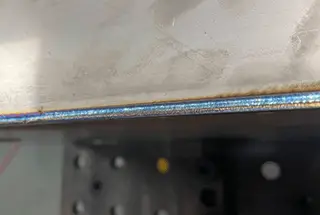
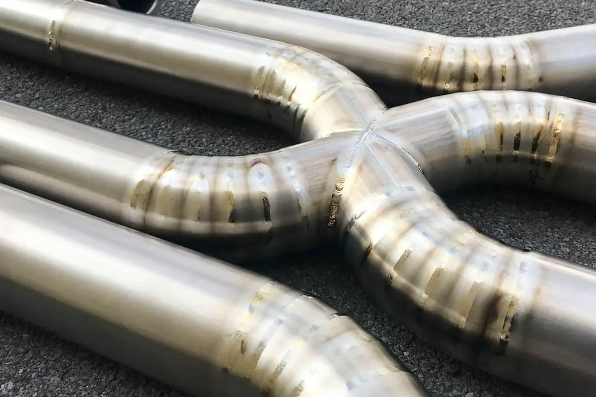
Since it is thin plate welding, we mainly judge the welding quality by observing the appearance of the weld bead and the color of the weld metal.
Mechanical performance tests of titanium alloy welds have shown that different colors of the weld surface correspond to different mechanical properties.
Colors of titanium alloy welds:
By selecting the correct welding method, adopting suitable welding parameters, and implementing appropriate process measures, we were able to meet the design requirements and successfully complete the entire production task.
Through this practice, we have gained valuable experience in welding titanium alloys, which will serve as a foundation for future projects undertaken by our company.

