Ever wondered why your solenoid valve isn’t working? This article explores the common faults of solenoid valves and provides practical troubleshooting steps. Learn how to diagnose issues such as coil failures, plug/socket problems, and valve core malfunctions. By understanding these solutions, you can maintain efficient operation and avoid downtime in your systems. Dive in to discover how you can ensure your solenoid valves are always functioning optimally.
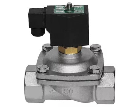
The solenoid valve coil is rated for a voltage of DC12V, DC24V, AC24V (50/60Hz), AC110V (50/60Hz), AC220V (50/60Hz), or AC380V (50/60Hz).
In electrical design, AC220V is often used because it does not require a switching power supply and is low cost, with a simple circuit and easy maintenance. Alternatively, DC24V is commonly used due to its widely used safety voltage and ease of repair and replacement of the switching power supply and solenoid valve coil.
To test the solenoid valve, first connect it to the controlled medium (such as a pressurized liquid or gas like air) with a pressure value in the middle range of the solenoid valve’s pressure range. Then, activate the solenoid coil.
If the controlled medium can change from on to off or off to on, the solenoid valve is functioning properly. If this is not the case, there may be an issue with the valve.
Detection method:
To diagnose the condition of a solenoid valve, use a multimeter to measure its on-off state. If the resistance tends towards zero or infinity, it indicates that the coil is either short-circuited or has an open circuit.
Even if the measured resistance is normal (around tens of Ω), it does not guarantee that the coil is functioning properly. I have encountered a case where the resistance of a solenoid valve coil was measured to be about 50 Ω, but the solenoid valve still did not work, and it was only after replacing the coil that everything returned to normal. To perform a final test, follow these steps:
Solution: replace the solenoid valve coil.
Fault phenomenon:
If the solenoid valve has a plug and socket connection, problems may arise with the metal spring of the socket or the wiring of the plug (such as connecting the power line to the ground wire), preventing power from reaching the coil.
It is recommended to develop a habit of securing the plug into the socket with a fixing screw, and securing the valve core rod with a fixing nut on the coil.
If the solenoid valve coil plug is equipped with an LED power indicator, it should be driven by a DC power supply, otherwise the indicator will not light up.
Note that different voltage level power plugs with LED power indicators should not be interchanged, as this may cause the LED to burn out, the power supply to short circuit, or the LED light to be very weak.
If there is no power indicator, the solenoid valve coil does not need to distinguish the polarity, unlike some transistor time relays with DC coil voltage or intermediate relays with a DC coil voltage and diode/resistor leakage circuit in parallel on the coil (mainly from Japan) that require polarity differentiation.
If there is a problem, the solution is to correct the wiring error, repair or replace the plug and socket.
Problem 1:
If the medium pressure in the solenoid valve is normal, but the red manual button of the solenoid valve fails to produce a response (i.e., no change in the on-off state of the pressure medium), it is likely that the valve core is broken.
Solution: First, check for problems in the medium, such as an excessive amount of water in compressed air (poor pipeline design can result in water in the compressed air reaching the solenoid valve, even if an oil-water separator is present) or impurities in the liquid medium.
Then, remove the water or impurities from the solenoid valve and pipeline. If this does not solve the problem, repair or replace the valve core, or the entire solenoid valve if necessary.
Problem 2:
If inspection shows that the coil is original and producing normal magnetism when powered on, but the solenoid valve still fails to act (at this time, the manual button of the solenoid valve may still function normally), it indicates that the valve core is broken.
Solution: Repair or replace the valve core, or the entire solenoid valve if necessary.
Note: There are many methods for maintaining solenoid valve bodies, but they will not be discussed here.
When a two-position valve receives an “on” or “off” signal from the Distributed Control System (DCS), the first step is to verify the solenoid coil’s operational status.
At the installation site, listen for any audible clicking or humming sounds associated with the valve’s actuation. The absence of such sounds may indicate a coil malfunction.
If a coil issue is suspected, follow these diagnostic steps:
Common causes of coil failure include:
If the coil tests satisfactorily, focus on the valve mechanism:
1. Manual override test: Attempt to actuate the valve using its manual override feature (typically adjusting from position 1 to 0). Successful manual actuation indicates a coil-related issue, which can be resolved by replacement.
2. Valve inspection: If manual actuation fails, remove the valve for internal examination. Look for:
3. Cleaning procedure:
Important: When disassembling the valve, document or photograph the component arrangement to ensure correct reassembly. Improper reassembly can result in valve malfunction or failure to open/close when energized.
Note: Always follow manufacturer guidelines and safety protocols when performing maintenance on solenoid valves. Ensure proper personal protective equipment (PPE) is used, especially when handling cleaning solvents.


