Why are round ducts often preferred over rectangular ones in HVAC systems? Despite the traditional use of rectangular ducts, modern engineering reveals that round ducts offer significant advantages. They are more cost-effective to manufacture, easier to install, and better at minimizing air leakage and pressure loss. This article explores these benefits, comparing initial investment, operating costs, and overall efficiency. By the end, you’ll understand why switching to round ducts could lead to substantial savings and improved performance in your HVAC projects.
The air duct system is a crucial component in air conditioning and ventilation engineering. Its purpose is to efficiently transport the adjusted air to the end equipment based on the designed flow.
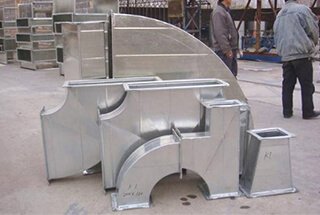
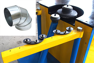
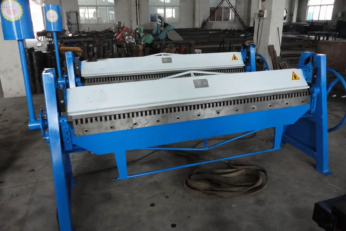
Typically, air ducts have three cross-sectional shapes: rectangular, circular, and oblong. Rectangular ducts are usually produced by riveting four steel plates together, while round ducts are created by winding a 137mm wide steel plate on a spiral forming machine. Oblong ducts are relatively uncommon and are typically formed by squeezing circular ducts.
Before 1960, rectangular ducts were the most widely used due to their simple manufacturing process and small installation space requirements. However, with the development of large spiral circular duct forming machines, many engineering projects have demonstrated that circular ducts are more economical and perform better in other engineering parameters compared to rectangular ducts.
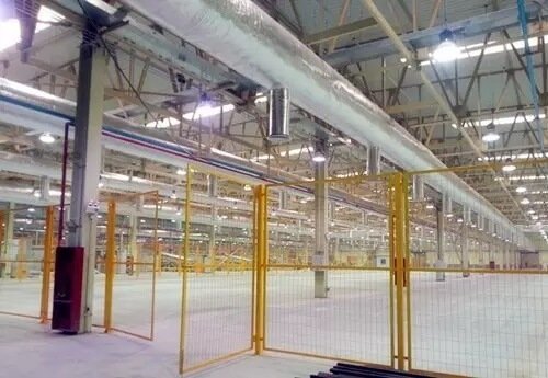
Many fiber fabric air ducts currently available in the market are air distribution systems that combine features such as air vents, air supply ducts, static pressure boxes, thermal insulation materials, and dampers. They have gained popularity among users due to their advantages such as accurate and uniform air supply, lightweight installation block, attractive appearance, and resistance to bacteria and mildew.
Fiber fabric ducts come in various shapes including round, semi-circular, quarter-circular, oval, and semi-oval to accommodate the requirements of different building structures.
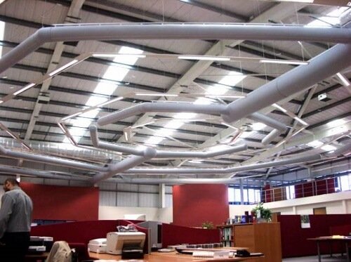
Round fiber fabric duct
Table 1: The market share of circular ducts each year:
| Country | 1960 | 1965 | 1970 | 1975 | 1980 | 1985 | 1990 | 2000 |
| Nordic | 5 | 15 | 40 | 60 | 70 | 80 | 85 | 90 |
| Germany | 5 | 5 | 10 | 15 | 20 | 25 | 25 | 50 |
| France | 5 | 10 | 20 | 30 | 40 | 50 | 50 | 65 |
| England | 5 | 10 | 15 | 20 | 25 | 35 | 35 | 55 |
From an economic analysis perspective, the total cost of an air duct system in a building throughout its service life can be divided into:
Foreign research has shown that, in many parameters, circular duct systems outperform rectangular duct systems.
This article will summarize the findings of these studies and concentrate on comparing the economic aspects of air duct systems.
It should be noted that, under normal circumstances, the renewal cost constitutes a small portion of the total cost, and therefore will not be considered in this discussion.
The reasons why the initial investment required for a circular duct system is lower than that of a rectangular duct system are as follows:
We designed two ventilation system schemes for a large room using circular and rectangular ducts, and compared the system’s pressure loss head and related economic parameters. The results, based on Nordic market prices from the year, are shown in Figure 1.
The calculations showed that, under the same end equipment conditions, the overall installation cost of the circular duct system was only half of that for the rectangular duct system, and the material cost of the circular duct system was 80% of that for the rectangular duct system.
 | 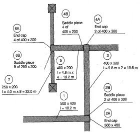 |
| Total pressure loss (Pa): 150.0 Total installation cost: 0.51R Total material cost: 0.8M (A) | Total pressure loss (Pa): 165.4 Total installation cost: R Total material cost: M (B) |
Figure 1: Comparison of duct design schemes
(A) Circular duct (B) Rectangular duct
Economic analysis of the space occupied by the duct system is challenging due to its dependence on the building’s structure and purpose.
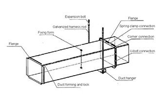
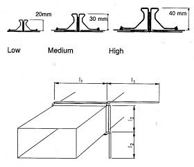
It is generally believed that rectangular ducts save space, but in reality, for rectangular ducts with a close aspect ratio, the actual area they occupy is larger than that of circular ducts. This is mainly because rectangular ducts require flanges for connection, and the height of the flange edges is typically greater than 20mm, as shown in Figure 2 (A).
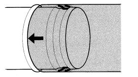
However, modern spiral air ducts can be connected with standardized flexibility, as shown in Figure 2 (B), which not only saves space but is also easier to install. Hence, for rectangular air ducts with an aspect ratio close to 1, the advantages of circular ducts cannot be overlooked.
 |
 |
| (A) | (B) |
Figure 2: Comparison of the duct connection scheme
(A) Rectangular duct (B) Circular duct
For rectangular ducts with large aspect ratios, they can be replaced with several circular ducts, as shown in Figure 3. This alternative can make controlling the air volume much easier and also reduce the installation costs. Although the cost of materials may increase, a survey showed that under this scheme, the initial investment is almost the same as that of the rectangular duct.
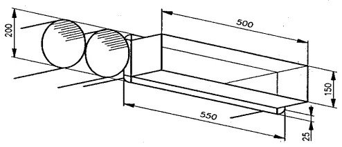
Figure 3: A alternative plan that 550mm × 150mm rectangular duct be replaced by two D = 200mm circular ducts
Under normal circumstances, the largest portion of operating costs for air conditioning systems is energy consumption. This includes the energy required to heat or cool the air and also to transport the air to the end equipment. If the entire duct system is well-insulated, the amount of air leakage from the ducts becomes a significant source of excess energy consumption.
For the duct system, the fan provides circulating power, and the wind pressure of the fan typically does not exceed 650Pa. Excluding the pressure loss at the end equipment of the air handling unit, the available pressure head of the entire duct system is around 200-300Pa.
Therefore, it is crucial to minimize the head loss to the air duct system. At the same time, the level of air leakage also directly affects the fan power selection. According to the fan theorem, fan power is proportional to the cube of the air volume. That is, if the air duct leakage rate is 6%, the fan power will increase by 20%. The leakage rate of circular air ducts is much smaller compared to rectangular air ducts.
The leakage rate of the air duct can be calculated by the following formula:

In Europe, the air-tightness of air ducts is divided into four levels (A, B, C, D) according to the air leakage constant.
Table 2 Shows the maximum allowable air leakage constants for the respective grades.
| Class A | KA= | 0.027×10⁻³ m3 s-1 m-2 Pa-0.65 |
| Class B | KB= | 0.009×10⁻³ m3 s-1 m-2 Pa-0.65 |
| Class C | KC= | 0.003×10⁻³ m3 s-1 m-2 Pa-0.65 |
| Class D | KD = | 0.001×10⁻³ m3 s-1 m-2 Pa-0.65 |
Table 2: Classification of air tightness in European duct systems
Comparison with circular ducts shows that rectangular ducts require significantly more bolts and rivets for connection, leading to much higher air leakage.
Figure 4 displays measured data from Belgium, which shows that the average leakage rate of rectangular ducts is seven times higher than that of circular ducts.
The “Code for Construction and Acceptance of Ventilation and Air Conditioning Work” GB50243-2002 also states that the allowed air leakage for circular ducts is 50% of that for rectangular ducts.
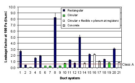
Figure 4: Measurements of air leakage rates in 21 Belgian buildings (Carrié et al, 1999)
The hydraulic equivalent is utilized to estimate the system pressure loss of rectangular ducts with the same hydraulic equivalent diameter. Despite their different cross-sectional shapes, they have the same pressure loss along the path.
Figure 5 compares the pressure loss of a circular duct (D = 0.5m, U = 5m/s, Σ = 0.15mm) and a rectangular duct with the same area and flow rate. It is evident that in this case, the pressure loss of the rectangular duct is much higher than that of the circular duct, and as the aspect ratio of the duct increases, the pressure loss increases. This implies that a larger fan power is required.
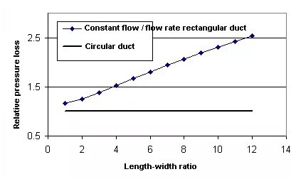
Figure 5: Comparison of pressure loss between rectangular duct and circular duct with constant flow and flow velocity (flow = 1m³ / s, v = 5m / s)
The concept of “hydraulic equivalent diameter” assumes that the average shear stress along the boundary of a rectangular duct should be consistent. In other words, the isokinetic line should be parallel to the air duct boundary. However, actual measurement results show that in a rectangular air duct, the speed gradient along the diagonal line decays the slowest and the speed gradient along the center line decays the slowest.
Therefore, in theory, the hydraulic equivalent diameter should be used with caution in the following two cases:
Experimental data also calls into question the universality of the hydraulic equivalent diameter. JONES conducted a series of experiments on the pressure loss of smooth rectangular ducts. The reanalysis of his experimental data is shown in Figure 6.
Despite the lack of data for 10 <aspect ratio <25, the data in Figure 6 still strongly suggest the monotonically increasing effect of length-width ratio on hydraulic equivalent diameter pressure loss.
Griggsetal’s experiments with rough rectangular ducts have similar results.
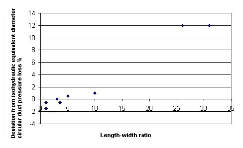
Figure 6: Comparison of pressure loss between smooth rectangular duct and circular duct with different length-width ratio
To prevent sick building syndrome, it is necessary to clean the air ducts regularly. The cleaning methods include dry method (using a vacuum cleaner and a brush) or wet method (using a long mop). In either case, cleaning circular ducts is easier than rectangular ducts.
Economic analysis of air duct systems is a challenging task. It must consider a range of factors, as the life of a duct system can often exceed ten years. In this case, a small improvement in design and quality can greatly increase the investment’s profitability.
Thus, the use of circular ducts is a more economical solution. However, it is important to note that for reasons such as quietness and space, rectangular ducts are still recommended for some large-flow and large-size components of the air duct system, such as fresh air intake vents and air treatment device outlets.

