The performance of sheet metal primarily involves its material characteristics, manufacturing processes, and design optimization. Firstly, the choice of sheet metal material significantly impacts its performance.
For instance, ferritic stainless steel and austenitic stainless steel, due to their varying chromium content, display different corrosion resistance and mechanical properties. Aluminum alloy sheets, depending on their alloy element content, are divided into several series, with the 2000 series commonly used for its excellent comprehensive performance.
Furthermore, materials like SGCC and SECC also differ in hardness, ductility, and weldability.
In terms of manufacturing processes, advances in sheet metal processing technology are crucial in enhancing the functionality and safety performance of sheet metal parts. Utilizing advanced techniques such as CNC punching and laser cutting can improve the precision and quality of sheet metal parts. Additionally, control of the process flow, such as cold forming, welding, and painting, is also a key factor in enhancing sheet metal performance.
Design optimization is another critical aspect of improving sheet metal performance. Avoiding flat design can enhance sheet metal strength, as pure flat sheet metal tends to deform under stress.
Moreover, determining the correct hole sizes, internal radii, and design details like bending height and radius are equally important for ensuring the shape accuracy and structural stability of sheet metal parts.

Mechanical Properties of Sheet Metal
① Tensile Strength
The maximum stress that a sheet metal material undergoes before breaking is known as the tensile strength. The unit of measurement is N/mm2 or MPa, and it is represented by the symbol σb. Tensile strength is one of the indicators of a metal’s overall strength.
② Bending Strength

The maximum stress that a cross section experiences when a load is applied between two points of a specimen is called the bend strength. The unit of measurement is N/mm2 or MPa, and it is represented by the symbol σbb. Bend strength is one of the indicators of a metal’s overall strength.
③ Compressive Strength

The maximum stress that a sheet metal material can endure under pressure without breaking is known as the compressive strength. The unit of measurement is N/mm2 or MPa, and it is represented by the symbol σbc.
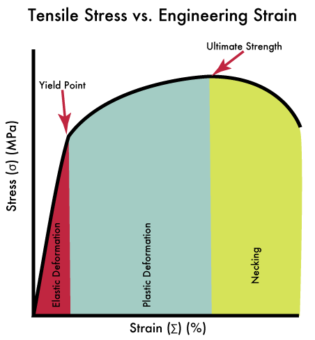
④ Yield Strength
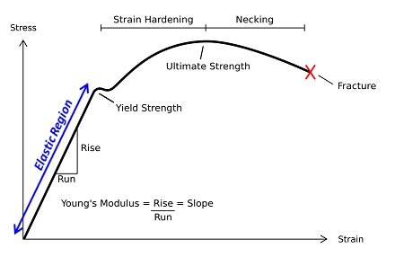
Yield strength refers to the stress of a metal sample during the stretching process when the load is no longer increasing but the sample continues to deform. The unit of measurement is N/mm2 or MPa, and it is represented by the symbol σs. The yield strength is the pressure value at the yield point.
For materials that do not exhibit an obvious yield point, the stress value that produces a 0.2% permanent deformation is often considered as the yield strength.
⑤ Shear Strength
It refers to the maximum load of the original cross-sectional area of the shear area before the sample shears.
The unit is: N/mm2 or MPa and symbol is στ.
⑥ Elastic Limit

It refers to the maximum stress of the specimen under the condition that the test piece deforms after the external force disappears and can recover the original condition.
The unit is: N/mm2 or MPa and symbol is σe.
⑦ Fracture Surface Shrinking Percentage
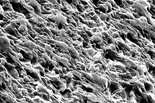
It is the percentage of the original cross-sectional area that is shrunk after tensile load.
The symbol is ψ and it is one of the plastic indexes of materials.
⑧ Elongation Ratio

Refers to the percentage of the elongation of the sample material and the original length after the sample material is breaking.
Elongation is also one of the plastic pointers of materials and symbol is δ.
⑨ Hardness
It refers to the ability of the material to resist hard pressing into its surface.
There are three types of hardness: Brinell hardness, Rockwell hardness and Vickers hardness.
Generally, the hardness of steel increases with the increase of carbon content in steel.
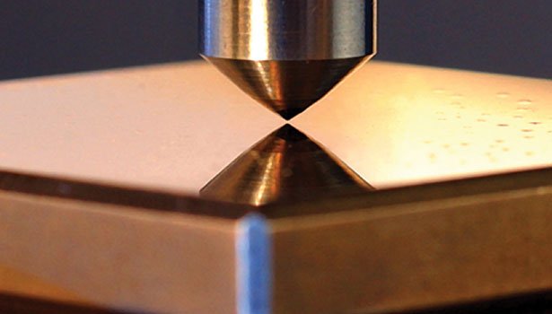
⑩ Brinell Hardness(HB)
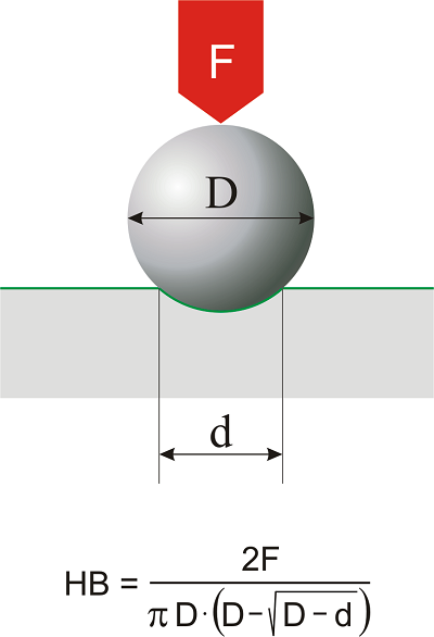
One way to represent hardness and measure it is through the Brinell hardness test. This test involves quenching a steel ball and then pressing it into the material surface under a specified load for a set period of time. The ratio of the applied pressure load to the area of the indentation is then calculated, and this ratio represents the Brinell hardness.
⑪ Rockwell Hardness (HR)
Another method of representing and measuring hardness is the Rockwell hardness test. This test involves pressing a diamond cone or steel ball after quenching into the material surface and then determining the hardness based on the depth of the indentation.
The Rockwell hardness is divided into three categories: HRA, HRB, and HRC, which are based on different test items and pressures.
HRA: The hardness value is obtained by applying 1470N of pressure using a diamond head with a 120-degree cone angle on the test samples. It is suitable for measuring the surface quenching layer, carburizing layer, and hard alloy materials.
HRB: The hardness value is obtained by applying 980N of pressure with a 1.59mm diameter steel ball. It is suitable for measuring soft metals such as nonferrous metals, annealed, and normalized steel.
HRC: The hardness value is obtained by applying 588N of pressure using a diamond cone with a 120-degree vertex angle on the test samples. It is suitable for measuring hard metals such as tempered steel and hardened steel.
Metal Mechanical Properties Chart
For the metal mechanical properties chart including shear strength, tensile strength, yield strength, you can check it out here.
What are the specific differences between SGCC and SECC materials in terms of hardness, ductility, and weldability?
The differences between SGCC and SECC materials in terms of hardness, ductility, and weldability manifest in the following ways:
Hardness: SGCC material is harder than SECC material. This could be attributed to the reduction annealing process during hot-dip galvanizing, which makes SGCC slightly harder.
Ductility: SGCC has inferior ductility. Due to its higher hardness, SGCC is prone to fractures or damage during stamping or deep-drawing designs, hence deep-drawing designs should be avoided in its application.
Weldability: SGCC has poorer weldability. This might be due to its thicker zinc layer, which can easily peel off during welding, affecting the welding quality. In contrast, although SECC is also a galvanized steel plate, its formability and paintability are superior to SGCC, which may indirectly reflect its advantage in weldability.
What are some successful cases or theoretical foundations for avoiding deformation of flat plate sheet metal under force through design optimization?
To avoid the problem of deformation in flat plate sheet metal under force through design optimization, the following methods can be adopted:
Add reinforcement ribs: By adding reinforcement ribs in the sheet metal part, the strength and rigidity of the sheet metal part can be improved. This method is simple and effective, and is suitable for situations where structural stability needs to be improved.
Add bends, flanges, or hemmed edges: These process operations can add extra layers of metal to the edges of the sheet metal part, thereby improving its tensile and compressive capacity. This design method helps to disperse stress, reduce local stress concentration, thereby enhancing the overall structural strength.
Add embossed bulges through wave formation: By adding embossed bulges to the surface of the sheet metal part, it can not only beautify the appearance but also increase the load-bearing capacity and resistance to deformation of the sheet metal part. This method is suitable for application scenarios with high requirements for structural performance.
Rational structural design: The design of sheet metal parts needs to consider the requirements and characteristics of its processing technology, while also taking into account batch size, cost, and production efficiency. Rational structural design is a prerequisite for ensuring that sheet metal parts have high strength and rigidity.
Utilize the design during the plastic deformation phase: According to plasticity theory, when the local material of the structure enters the plastic deformation stage, the stress will redistribute to make the stress distribution more uniform, thereby improving the load-bearing capacity of the structure. Therefore, considering suitable plastic deformation in the design can make the structure more stable under force, avoiding deformation caused by excessive stress concentration.
In sheet metal design, how significant is the impact of correct hole sizes, internal radii, and bend heights and radii on enhancing the performance of sheet metal?
In sheet metal part design, the correct hole size, internal radius, and bending height and radius significantly impact the performance of the sheet metal. Firstly, hole positioning must account for the influence of the manufacturing process. For instance, holes positioned too close to the edge may deform or even crack due to material stretching, highlighting the importance of proper hole design in avoiding manufacturing issues.
Moreover, the minimum size of the punched hole is related to the hole’s shape, the mechanical properties of the material, and the thickness of the material. These factors must be considered during the design to ensure the punching process does not damage the punch or compromise the final product’s quality.
The bending height should be at least twice the sheet metal thickness plus the bending radius. This design principle helps ensure uniform plastic deformation of the material during the bending process, thereby improving the accuracy and quality of the sheet metal parts.
If the design requires a straight edge height less than twice the sheet metal thickness, measures should be taken to increase the bending height to avoid processing shallow grooves in the bending deformation zone before bending, ensuring the quality of the bending formation.
The number of bending operations in sheet metal part fabrication also directly affects the mold cost and bending accuracy. Reducing the number of bending operations can lower the mold cost and improve bending accuracy, so it’s crucial to minimize bending operations during design.
Furthermore, the outer shape and inner holes of the punched parts should avoid sharp corners, as sharp corners can affect the lifespan of the mold. This is another important factor to consider during sheet metal part design.
The correct hole size, internal radius, and bending height and radius are vital for enhancing sheet metal performance. By reasonably designing these parameters, manufacturing issues can be effectively avoided, and the quality and accuracy of the sheet metal parts can be improved. Simultaneously, it can also help reduce costs and improve production efficiency.

Good to have all your information in my recorders and to share all these with my budding junior engineers. Email me all such related information of Mechanical Engineering. Your small action are big big information to all engineers out here. Thank you.
I believe to keep our website site address in your mind is better, why not share our site with your engineers.
Noted, Thank you.
Thanks for all the info
You’re welcome.